EP1447367B1 - Procédé et dispositif pour la surveillance d'un poste de travail d'une machine textile - Google Patents
Procédé et dispositif pour la surveillance d'un poste de travail d'une machine textile Download PDFInfo
- Publication number
- EP1447367B1 EP1447367B1 EP20030028862 EP03028862A EP1447367B1 EP 1447367 B1 EP1447367 B1 EP 1447367B1 EP 20030028862 EP20030028862 EP 20030028862 EP 03028862 A EP03028862 A EP 03028862A EP 1447367 B1 EP1447367 B1 EP 1447367B1
- Authority
- EP
- European Patent Office
- Prior art keywords
- thread
- accordance
- suction tube
- cutting
- procedure
- Prior art date
- Legal status (The legal status is an assumption and is not a legal conclusion. Google has not performed a legal analysis and makes no representation as to the accuracy of the status listed.)
- Expired - Lifetime
Links
Images



Classifications
-
- B—PERFORMING OPERATIONS; TRANSPORTING
- B65—CONVEYING; PACKING; STORING; HANDLING THIN OR FILAMENTARY MATERIAL
- B65H—HANDLING THIN OR FILAMENTARY MATERIAL, e.g. SHEETS, WEBS, CABLES
- B65H54/00—Winding, coiling, or depositing filamentary material
- B65H54/70—Other constructional features of yarn-winding machines
- B65H54/71—Arrangements for severing filamentary materials
-
- B—PERFORMING OPERATIONS; TRANSPORTING
- B65—CONVEYING; PACKING; STORING; HANDLING THIN OR FILAMENTARY MATERIAL
- B65H—HANDLING THIN OR FILAMENTARY MATERIAL, e.g. SHEETS, WEBS, CABLES
- B65H65/00—Securing material to cores or formers
-
- B—PERFORMING OPERATIONS; TRANSPORTING
- B65—CONVEYING; PACKING; STORING; HANDLING THIN OR FILAMENTARY MATERIAL
- B65H—HANDLING THIN OR FILAMENTARY MATERIAL, e.g. SHEETS, WEBS, CABLES
- B65H2701/00—Handled material; Storage means
- B65H2701/30—Handled filamentary material
- B65H2701/31—Textiles threads or artificial strands of filaments
Definitions
- the present invention relates to a method according to the preamble of claim 1 and to an apparatus for carrying out this method (US-A-196 44 593).
- the increase in the restraining force can be effected in various ways, for example by intensifying the suction air flow entering the intake manifold.
- intensifying the suction air flow entering the intake manifold As a particularly simple and also extremely effective measure, a retention of the thread according to claim 2 and optionally also according to claim 3 has been found.
- An increase in the safety against cutting can be achieved according to claim 4 by an additional movement of the suction tube, which retains the thread to be cut by clamping.
- the function to be triggered when a cutting fault occurs may vary.
- a device independent of the thread cutting device a separation process is performed.
- the tension in the thread section extending from the thread cutting device into the suction tube can advantageously be used in accordance with claim 8.
- the increase of the retention force is exerted by means of friction force.
- it can be difficult to exert a sufficiently large restraining force on a thread solely by negative pressure, for example in a straight tube.
- a mechanical retention for example by means of a clamping device, a corresponding feed movement, including the necessary clamping device.
- the frictional force is generated by wrapping one or more bodies. It is conceivable, for example, to redirect the thread through a plurality of bodies and in this way to produce a friction length that is sufficiently large in total. Another alternative is to wrap a cylinder, for example, simply or even several times and to keep the thread running from these cylinders at its loose end with different suction or holding forces. Here, a relatively small holding force on the loose thread end is sufficient to prevent inadvertent pulling out of the thread during the cutting process.
- the principle of self-locking is used, as it is used for example on winches on sailing ships.
- the wraps are helical.
- the suctioned by vacuum thread is held simultaneously by the suction force and the frictional force.
- this can be achieved, inter alia, by increasing the length of the loop. This is particularly easy in the wrapping of a cylindrical body possible where by adding individual turns the looped length is particularly easy to enlarge.
- a device is used to carry out the method described above.
- the thread restraining device which is preferably designed as a clamping device, causes the thread to be severed to be held taut and does not have the opportunity to give way and thereby make it difficult to sever.
- this clamping device in the vicinity of the inlet mouth of the suction tube according to claim 18 whose effectiveness is particularly high, since the retained by this clamping thread receives no way to slacken due to a possibly longitudinal elasticity, thereby complicating the severing of the thread or even impossible do.
- the clamping device is simultaneously formed as a shut-off valve, so that fluttering of the thread portion is avoided on the relative to the clamping device of the winding device side facing and thus an uncontrolled yielding of the thread during the cutting process.
- a thread monitoring device for the thread extending from the winding device to the suction tube can be provided according to claim 22 or 23.
- a control device triggers a suitable function in case of malfunction of the thread cutting device, so that correspondingly quickly remedy can be created.
- At least one body deflects the course of the thread.
- either one or more bodies can be used. It is conceivable, for example, the arrangement of a plurality of individual bodies, which form a labyrinth, which deflects the passing thread. By deflecting the used for restraint required friction force is then generated, which fixes the thread.
- the body is a vacuum hose.
- a hose is particularly easy to deform and thus adapt to the required geometry.
- the passing thread may rest against the inner walls designed as friction surfaces, via which in turn the required frictional force is applied.
- Another particularly advantageous embodiment provides to increase the retention force that is reduced by means of an adjusting device, the flow cross section in the region of the thread from the control device, at least during the cutting process.
- the method according to the invention and the device according to the present invention in a simple manner bring about a substantial increase in the certainty that the thread section to be wound onto the empty tube is separated from the thread section extending into the suction tube. In this way it is prevented that extends from the winding device to the arranged on the maintenance device suction pipe, a thread section which is pulled by the continuation of their maintenance work completed maintenance device on parts of the adjacent jobs and there impaired the reliability or the subsequent further processing of Thread hindered, which has been wound onto the coils of adjacent jobs, so that occur in subsequent operations disorders.
- the advantage is achieved that the necessary device is very simple in construction and thus inexpensive to manufacture and can be used.
- textile machines can also be retrofitted with the device according to the invention with little effort.
- the invention can be applied to various textile machines on which a running thread F for winding to an empty tube H (see Fig. 1) is to pass, for example, to a winder or an open-end spinning machine.
- the following description relates to an open-end spinning machine with a plurality of similarly trained, juxtaposed open-end spinning devices 1, each of which has a discharge pipe 10 through which the thread F by means of draw-off rollers 11, 12 from the open-end spinning device. 1 can be deducted to be fed to a winding device 4.
- This one has two on one Axle 42 pivotally mounted Spularme 40 and 41, between which with the aid of two rotatably mounted in the Spularmen 40 and 41 sleeve plate 400 and 411 an empty tube H can be inserted, on which the thread F is to be wound.
- one of the sleeve plates, in the exemplary embodiment of the sleeve plates 400 is designed as a catching device 47 and has a multiplicity of catching hooks 470 for this purpose.
- a presentation device 2 For the presentation of the thread F for receiving by the catching device 47, a presentation device 2 is provided. This has a suction tube 20 and a thread guide 21 which are arranged on a common holder 22.
- the presentation device 2 is mounted on a maintenance device 3 (indicated by dashed lines in FIG. 4) in such a manner that it can be delivered to the safety device 47 for carrying out its work and then retracted back into a rest position within the maintenance device 3.
- the maintenance device 3 is usually designed to perform various maintenance and runs along a variety of similar, juxtaposed jobs.
- this is designed as a clamping device and has a controllable clamping element 80 which in a provided in the suction tube 20 guide 81st is movably guided, which is formed in the manner of an inner circumferential groove of the suction tube 20.
- the clamping element 80 is connected to a drive rod 82, which forms the armature of an electrical coil 83 and therefore extends into it.
- This coil 83 is supported by a suitably mounted holding device 84, which is supported in a manner not shown by elements of the maintenance device 3.
- the holding device 84 is designed as a housing and also carries the inlet mouth 200 of the suction tube 20.
- the coil 83 is connected by means of a control line 90 to a control device 9 (FIG. 4) which is located on the maintenance device 3.
- the control device 9 in turn is connected by means of a control line 901 to a superordinate control device, not shown.
- drivable winding roller 43 is provided (Fig. 1), in front of which a traverse rod 44, each with a designed as a self-threader traverse guide 45 per Winding device 4 is to take the thread F after successful transfer to the empty tube H and to move iridescent to form a coil can.
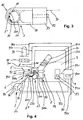
- the thread cutting device 6 has in the illustrated embodiment, a blade 60 with a thread cutting edge 600.
- the blade 60 is angled outside the working range of the thread cutting edge 600 at right angles and thus has a mounting portion 601, with the aid of the blade 60 with the interposition of a spacer 61 am Spularm 40 is attached.
- the thread F which has previously been wound in a known and customary manner with the aid of the mentioned maintenance device 3 and in per se conventional manner in the presentation device 2 is withdrawn by means of the take-off rolls 11 and 12 through the thread withdrawal tube 10 of the open-end spinning device 1 and via the thread guide 21 into the inlet mouth 200 of the aforementioned suction tube 20 and continuously discharged through this.
- the maintenance device 3 now pivots the presentation device 2 from its not shown thread receiving position towards the catching device 47, of which one of the rotating fishing hooks 470 extending from the thread guide 21 to the inlet mouth 200 of the suction tube 20 substantially parallel to the axis of the empty tube H and thus substantially perpendicular to the orbit of the fishing hooks 470 extending thread section takes.
- the thread section F '(FIG. 2) of the thread F grasped by the catch hook 470 of the catching device 47 which is in relation to the catch hook 470 on the side facing the empty tube H, is due to the training known per se the sleeve plate 400 between segments 401, which project beyond the empty tube H and are supported by the sleeve plate 400, and the peripheral surface of the empty tube H clamped and thereby secured. Then passes the current of the empty tube H using the take-off rollers 11, 12 supplied thread F in the nip L between the empty tube H and the winding roller 43 and will be wound up on the empty tube H.
- the control device 9 In timing with the transfer of the held by the presentation device 2 thread F to the safety gear 47, the control device 9 outputs a control signal to the coil 83 of the thread restraint 8, which now causes the force acting on the thread F retaining force is increased compared to that Retaining force that was previously generated by the pressure prevailing in the intake manifold 20 vacuum.
- the retention force is increased by bringing the clamping element 80 into its clamping position, in which it clamps the thread section F ", which extends from the catch hook 470 to the inlet mouth 200 of the suction tube 20.
- This thread section F is pulled along and along the thread cutting edge 600 during the rotation of the catch hook 470, thereby severing the thread F.
- the thread section F is prevented from clamping by a pinch Give train in the direction of thread cutting device 6.
- the thread F has no possibility to yield during cutting, so that the thread section F "of the thread cutting device 6 to be cut is presented in a streamlined state, which leads to a high level of cutting safety.
- the spool 83 of the thread retaining device 8 is again controlled by the control device 9, whereupon the spool 83 retracts the clamping element 80 into its thread release position.
- the severed thread section F "is released and removed through the suction tube 20.
- the presentation device 2 is no longer needed and therefore removed from the area of the catching device 47.
- controllable thread retaining device 8 at any point on the suction tube 20 facing side of the thread cutting device 6 to arrange. This can also be stored completely independently of the suction tube 20, for example on the spool 40. It is expedient to arrange this thread retaining device 8 in the greatest possible proximity of the thread cutting device 6.
- the clamping element 80 may be designed such that in its clamping position substantially the entire inner cross section of the suction tube 20 is shut off and thus formed as a shut-off valve 85 (FIG. 3). The inner cross-section of the suction tube 20 is thereby blocked off as far as the thread section F "extending into the suction tube 20 permits, which is now clamped between the inner wall 201 of the suction tube 20 and the clamping element 80.
- the suction tube 20 carries out an additional movement through which the thread F retained by the clamping element 80 both at the inlet mouth 200 of the suction tube 20 and at the thread cutting edge 600 undergoes even greater deflection and above all rests with an even higher contact pressure at the thread cutting edge 600. In this way, the security against cutting of the thread cutting device 6 is considerably increased.
- the thread cutting edge 600 changes its cutting behavior over time. This gradual reduction of the cutting quality can be controlled poorly, as even with deteriorating cutting quality, a separation process is still performed due to the fact that arranged in the presentation device 2 retaining device 8, possibly in conjunction with an additional movement of the suction tube 20, the severing thread F keeps, so that despite a no longer perfectly cutting thread cutting edge 600 of the thread F is severed at least by tearing.
- a thread separating device 23 (FIG. 4) can be arranged in the mouth region of the suction tube 20. This is formed according to the embodiment shown by the edge of the inlet mouth 200 of the suction tube 20 or at least that peripheral region thereof, on which the hineinzerstreck in the suction tube 20 thread section F "applies and which is designed for this purpose as a sharp-edged cutting edge 230.
- such a thread separating device 23 is not formed by the inlet mouth 200 of the suction tube 20, but by another element (not shown) arranged in front of this inlet mouth 200. This can be suitably controlled, but this thread separating device 23 is preferably designed so that it does not require its own control, but causes the severing of the thread F alone due to the system pressure.
- this edge at the inlet mouth 200 of the suction tube 20 is not sharp-edged, d. H. not as a cutting edge 230, is formed, it may nevertheless in a suitable manner, for. B. by means of an additional movement of the suction tube 20 with the clamped thread section F ", provided that this thread section F" is severed at this edge, at least by tearing.
- suction tube 20 is with its inlet mouth 200 during the yarn transfer to the safety gear 47 and during the severing of the thread F by means of the thread cutting device 6 in the vicinity, For example, even if the severing of the thread F has to be performed by means of the thread-separating device 23 independent of the thread-cutting device 6, thread ends are achieved which are not substantially longer than those produced when the thread-cutting device 6 operates properly.
- the thread section F "extending from the thread cutting device 6 to the suction tube 20 can be monitored
- the previously described device according to FIG. 4 can be supplemented by a thread monitoring device 91 which is connected to the control device 9 by means of a control line 912.
- the thread monitoring device 91 is formed by a lug 910 on the outer circumference of the suction tube 20 on the one hand and a coil 911 on the other hand
- an intermediate section of the suction tube 20 is designed as an elastic tube 202 for this purpose.
- either the depth of immersion of the flag 910 connected to the armature of the coil 911 or its distance to the two pole shoes 911a and 911b of the coil changes 911, which leads to a predetermined action or to trigger a predetermined function by the control device 9.
- the yarn monitoring device 91 described above can also be designed as a presence sensor. However, since a presence sensor responds only when the thread is missing, that is, after the thread F has been severed in any way, is provided in such a configuration of the thread monitor 91 that the control device 9, the time from the initiation of the cutting process by the thread cutting device 6 to Absence of the thread section F "on such a thread presence sensor measures to allow the control device 9 in response to This time corresponding functions can trigger, as will be described later.
- the control device 9 is connected via a control line 920 with a control valve 92 for a cleaning device 7 in the embodiment shown.
- This is stored in the embodiment shown in the maintenance device 3 and can if necessary, for example, after each unsuccessful cutting attempt of the thread cutting device 6, by request by the control device 9 of the thread cutting edge 600 of the thread cutting device 6 to perform a cleaning of the blade 60.
- the cleaning device 7 is pneumatically formed and has a compressed air nozzle 70.
- control device 9 can be assigned an evaluation device 93. This is an integrated part of the control device 9 or connected to it by means of a control line 931.
- the thread monitoring device 91 notifies the latter to the control device 9, from which corresponding control pulses are supplied to the evaluation device 93, in which these pulses are counted.
- the evaluation device 93 is adjustable and has a setting field 930 for this purpose reached with the help of the setting field 930 previously specified count for reported cutting error, the evaluation device 93 activates the control device 9, which then triggers one or more predetermined activities or functions.
- the control device 9 may also be adjustable for the determination of such functions to be triggered and have a corresponding adjustment field 900 or allow a different data input, for example by means of a CD-ROM or the like.
- an alarm device 94 is connected to the control device 9 by means of a control line 940, for example, which is addressed upon reaching the number of malfunctions of the thread cutting device 6 determined by the evaluation device 93 and emits an optical and / or acoustic alarm signal.
- a shutdown of the affected job in which the thread cutting device 6 can no longer properly perform their cutting work, are triggered.
- a control line 950 can also be addressed a display device 95, which displays this number of malfunctions, possibly even in dependence on the production period, so that the operator can understand whether the condition of the thread cutting device 6 has deteriorated or not.
- the display device 95 can be addressed at each cutting error and thus already indicate the number of malfunctions of the thread cutting device 6, even before the value determined in the evaluation device 93 has been reached.
- FIG. 5 shows a suction tube 20 of a presentation device 2 according to the invention with a number of associated components in a side view. To illustrate the embodiment was based on a drawing Representation of the remaining to the delivery device 2 associated components omitted.
- the thread F first enters through the inlet mouth 200 in the suction tube 20 a.
- the hose 202 connects.
- the hose 202 is designed as a flexible vacuum hose.
- the strength of the tube walls is large enough to absorb the resulting by the pressure prevailing inside the forces and not to invade. When applied vacuum, the hose 202 therefore largely retains its cross-sectional shape.
- the course of the hose 202 is characterized by a hose turn 203, in which the hose 202 makes a full 360 ° rotation.
- an adjusting device 96 is arranged at the outlet of the hose winding 202.
- the flow cross-section of the tube 202 can optionally be reduced or increased by delivering a punch 961.
- the adjusting device 96 is connected via a control line 960 to the control device 9.
- a vacuum source 97 which is connected in a control manner with the control device 9 is a vacuum source 97, which is connected via a control line 970.
- the retention process of the thread F then proceeds as follows. First, the thread F is sucked by means of the air flow generated by the negative pressure source 97 into the tube. The loose end of the thread runs through the tube winding 203 until it finally finally arrived behind the actuator 96.
- the suction or holding force generated by the air flow in the tube 202 keeps it in its position.
- the thread F is also held by the frictional force generated between it and the tube inner wall 201. This makes it possible with a relatively small suction or holding force, z. B. in the region of the adjusting device 96 to produce a much larger retention force in the region of the inlet opening 200. To pull out then only the force exerted by the air flow on the thread F suction must be canceled. The suction, on the other hand, if necessary, for. B.
- the tubular embodiment of the deflecting body shown has the advantage that the thread can be sucked in automatically by the negative pressure.
- Conceivable are other embodiments in which the thread is wound, for example, over a roller before it detects the air flow and thus the suction force.
Landscapes
- Engineering & Computer Science (AREA)
- Textile Engineering (AREA)
- Replacing, Conveying, And Pick-Finding For Filamentary Materials (AREA)
- Looms (AREA)
- Treatment Of Fiber Materials (AREA)
Claims (33)
- Procédé pour la maintenance d'un poste de travail d'une machine textile, dans lequel un fil est amené au moyen d'un tuyau d'aspiration d'un dispositif de bobinage raccordé à un tuyau à dépression, dans lequel ledit dispositif de bobinage capture le fil et le conduit à un dispositif coupe-fil en vue de la coupe, caractérisé en ce que la force de retenue augmente sur le fil s'étendant dans le tuyau d'aspiration au moins pendant la procédure de coupe à effectuer et en syntonisation dans le temps avec l'amenée du fil vers le dispositif coupe-fil.
- Procédé selon la revendication de brevet 1, caractérisé en ce que pour l'augmentation de la force de retenue, le fil est serré dans le tuyau d'aspiration ou dans son voisinage pendant la durée de la procédure de coupe et qu'il est libéré à nouveau immédiatement pour l'évacuation du segment de fil coupé.
- Procédé selon la revendication de brevet 2, caractérisé en ce que le segment de fil s'étendant du dispositif coupe-fil au tuyau d'aspiration n'est exposé à aucune dépression pendant le serrage.
- Procédé selon l'une quelconque des revendications de brevet précédentes, caractérisé en ce que la pression de serrage du fil retenu par serrage dans le tuyau d'aspiration contre le dispositif coupe-fil est augmentée par un mouvement supplémentaire du tuyau d'aspiration.
- Procédé selon l'une quelconque des revendications de brevet précédentes, caractérisé en ce que le fil s'étendant du dispositif coupe-fil vers le tuyau d'aspiration fait l'objet d'une surveillance et qu'une fonction déterminée se déclenche à l'identification d'une perturbation de la coupe.
- Procédé selon l'une quelconque des revendications de brevet précédentes, caractérisé en ce que pour identifier une perturbation de la coupe, la tension du segment de fil s'étendant du dispositif coupe-fil vers le tuyau d'aspiration est soumis à une surveillance.
- Procédé selon l'une quelconque des revendications de brevet précédentes, caractérisé en ce qu'à la détection d'une perturbation de la coupe, une procédure de coupe du fil supplémentaire indépendante de la procédure de coupe à effectuer par le dispositif coupe-fil est déclenché.
- Procédé selon l'une quelconque des revendications de brevet précédentes, caractérisé en ce que la procédure de coupe du fil supplémentaire est déclenchée en fonction de la tension du fil s'étendant du dispositif de bobinage vers le tuyau d'aspiration.
- Procédé selon l'une quelconque des revendications de brevet précédentes, caractérisé en ce qu'à l'apparition d'une perturbation de la coupe, une alarme et/ou une mise à l'arrêt du poste de travail concerné est déclenchée.
- Procédé selon l'une quelconque des revendications de brevet précédentes, caractérisé en ce qu'à l'apparition d'une perturbation de la coupe, un nettoyage du dispositif de coupe est déclenché en syntonisation dans le temps avec la tentative de coupe échouée.
- Procédé selon l'une quelconque des revendications de brevet précédentes, caractérisé en ce que l'augmentation de la force de retenue est effectuée par une force de frottement.
- Procédé selon la revendication de brevet précédente, caractérisé en ce que la force de frottement est générée par enroulement d'un ou de plusieurs corps.
- Procédé selon l'une quelconque des revendications de brevet précédentes, caractérisé en ce que l'enroulement se présente sous forme hélicoïdale.
- Procédé selon l'une quelconque des revendications de brevet précédentes, caractérisé en ce que le fil aspiré au moyen de la dépression est retenue simultanément par une force d'aspiration et la force de frottement.
- Procédé selon l'une quelconque des revendications de brevet précédentes, caractérisé en ce que pour l'augmentation de la force de retenue, la longueur de l'enroulement est augmentée.
- Procédé selon l'une quelconque des revendications de brevet précédentes, caractérisé en ce que pour l'augmentation de la force de retenue, un débit volumique d'un volume d'air aspiré par la dépression est augmenté et/ou qu'une section de passage est réduite.
- Dispositif pour la maintenance d'un poste de travail d'une machine textile, avec un dispositif de bobinage (4) servant au bobinage d'un fil (F), avec un dispositif de maintenance (3) déplaçable le long d'une multitude de postes de travail de même type, avec en outre un tuyau d'aspiration (20) disposé dans le dispositif de maintenance et auquel une dépression est applicable, servant à l'amenée du fil à bobiner au dispositif de bobinage ainsi qu'avec un dispositif de racroc (4) logé sur palier rotatif servant à accueillir le fil qui lui est amené par le tuyau d'aspiration, ainsi qu'avec un dispositif coupe-fil (6) stationnaire par rapport à ce dispositif de racroc actionnable et servant à couper le fil et permettant la mise en pratique du procédé selon l'une quelconque ou plusieurs des revendications de brevet 1 à 10, caractérisé en ce qu'un dispositif de retenue du fil (8) se présentant de préférence sous la forme d'un dispositif de serrage asserviable est disposé sur le côté du dispositif coupe-fil (6) orienté vers le tuyau d'aspiration (20).
- Dispositif selon la revendication de brevet 17, caractérisé en ce que le dispositif de serrage asserviable (8) est disposé près de l'orifice d'entrée (200), de préférence au sein du tuyau d'aspiration (20).
- Dispositif selon l'une quelconque des revendications de brevet 17 ou 18, caractérisé en ce qu'une soupape d'arrêt (85) constituée de préférence par le dispositif de serrage asserviable est disposée dans le tuyau d'aspiration (20).
- Dispositif selon l'une quelconque ou plusieurs des revendications de brevet 17 à 18, caractérisé en ce qu'un dispositif de séparation de fil (23) est disposé dans la zone de l'orifice du tuyau d'aspiration (20).
- Dispositif selon la revendication de brevet 20, caractérisé en ce que le dispositif de séparation du fil (23) est constituée de préférence par le bord d'orifice du tuyau d'aspiration (20), se présentant de préférence sous la forme d'un bord de coupe (230).
- Dispositif selon l'une quelconque ou plusieurs des revendications de brevet 17 à 21, caractérisé en ce que pour la surveillance du fil (F) s'étendant du dispositif coupe-fil stationnaire (6) au tuyau d'aspiration (20), il est prévu un dispositif de surveillance du fil (91) se présentant de préférence sous la forme d'un dispositif de mesure de la tension du fil, qui est relié en asservissement à un dispositif de commande (9).
- Dispositif selon la revendication de brevet 22, caractérisé en ce que le tuyau d'aspiration (20) est maintenu de telle manière qu'il exécute des mouvements transversaux selon la tension du fil et que le dispositif de surveillance du fil (91) est attribué au tuyau d'aspiration (20) de telle manière qu'il enregistre ces mouvements transversaux.
- Dispositif selon l'une quelconque des revendications de brevet précédentes, caractérisé en ce qu'un dispositif d'évaluation (93) est attribué au dispositif de commande (9), qui déclenche une fonction déterminée une fois qu'est atteint un nombre déterminé de perturbations de la coupe.
- Dispositif selon l'une quelconque des revendications de brevet précédentes, caractérisé en ce que le dispositif de commande (9) est en relation d'asservissement avec un dispositif d'affichage (95) et/ou un dispositif d'alarme (94).
- Dispositif selon l'une quelconque des revendications de brevet précédentes, caractérisé en ce que le dispositif de commande (9) est en relation d'asservissement avec un dispositif de nettoyage (7) attribué au dispositif coupe-fil stationnaire (6).
- Dispositif selon l'une quelconque des revendications de brevet précédentes, caractérisé en ce que pour générer une force de frottement, au moins un corps change la direction de la translation du fil.
- Dispositif selon la revendication de brevet précédente, caractérisé en ce que le corps est un tuyau à dépression.
- Dispositif selon l'une quelconque des revendications de brevet précédentes, caractérisé en ce que le tuyau à dépression se présente sous forme hélicoïdale.
- Dispositif selon l'une quelconque des revendications de brevet précédentes, caractérisé en ce qu'il existe un coefficient de frottement entre la surface de contact du fil au corps et le fil lui-même, lequel est suffisamment grand pour que le fil soit sûrement arrêté lors de la coupe.
- Dispositif selon l'une quelconque des revendications de brevet précédentes, caractérisé en ce que la surface de contact du corps est rendue rugueuse.
- Dispositif selon l'une quelconque des revendications de brevet précédentes, caractérisé en ce que pour augmenter la force de retenue, un dispositif de régulation augmente le débit volumique généré par la dépression au moins pendant la procédure de coupe.
- Dispositif selon l'une quelconque des revendications de brevet précédentes, caractérisé en ce que pour augmenter la force de retenue, le dispositif de régulation, au moyen d'un dispositif de manoeuvre, diminue la section de passage dans la zone du fil au moins pendant la procédure de coupe.
Applications Claiming Priority (2)
| Application Number | Priority Date | Filing Date | Title |
|---|---|---|---|
| DE2003106402 DE10306402A1 (de) | 2003-02-15 | 2003-02-15 | Verfahren und Vorrichtung zum Warten einer Arbeitsstelle einer Textilmaschine |
| DE10306402 | 2003-02-15 |
Publications (2)
| Publication Number | Publication Date |
|---|---|
| EP1447367A1 EP1447367A1 (fr) | 2004-08-18 |
| EP1447367B1 true EP1447367B1 (fr) | 2006-08-23 |
Family
ID=32668078
Family Applications (1)
| Application Number | Title | Priority Date | Filing Date |
|---|---|---|---|
| EP20030028862 Expired - Lifetime EP1447367B1 (fr) | 2003-02-15 | 2003-12-16 | Procédé et dispositif pour la surveillance d'un poste de travail d'une machine textile |
Country Status (3)
| Country | Link |
|---|---|
| EP (1) | EP1447367B1 (fr) |
| CN (1) | CN1314572C (fr) |
| DE (2) | DE10306402A1 (fr) |
Families Citing this family (2)
| Publication number | Priority date | Publication date | Assignee | Title |
|---|---|---|---|---|
| EP3597581B1 (fr) * | 2018-07-17 | 2021-02-24 | Starlinger & Co Gesellschaft m.b.H. | Dispositif d'enroulement d'une bande |
| CN119797075B (zh) * | 2025-03-14 | 2025-06-17 | 上海华翔羊毛衫有限公司 | 一种用于羊毛衫残次品纱线的回收装置 |
Family Cites Families (14)
| Publication number | Priority date | Publication date | Assignee | Title |
|---|---|---|---|---|
| CH593856A5 (fr) * | 1975-04-16 | 1977-12-15 | Rieter Ag Maschf | |
| US4084759A (en) * | 1976-05-17 | 1978-04-18 | Nuova San Giorgio S.P.A. | Method and a device for winding up a yarn reserve |
| DE2705392A1 (de) * | 1977-02-09 | 1978-08-10 | Luwa Ag | Verfahren und vorrichtung zum anschluss eines garns und zur bildung einer garnreserve auf einer garnhuelse |
| DE3725889A1 (de) * | 1987-08-05 | 1989-02-16 | Gebald Gregor | Verfahren zum vorbereiten von kreuzspulen fuer eine doppeldrahtvorlage |
| DE3726337A1 (de) * | 1987-08-07 | 1989-02-16 | Mayer Fa Karl | Fadenendesuchvorrichtung |
| DE4012800C2 (de) * | 1989-04-29 | 1994-09-29 | Barmag Barmer Maschf | Fadenabsaugeinrichtung |
| DE4004028C2 (de) * | 1990-02-10 | 2001-06-07 | Schlafhorst & Co W | Verfahren und Vorrichtung zum Bilden einer Fadenreserve auf einer Kreuzspule |
| DE4241449A1 (de) * | 1992-12-09 | 1994-06-16 | Schlafhorst & Co W | Vorrichtung zum Lösen des Hinterwindungsfadens von der Oberfläche von Kopsen |
| DE4337551A1 (de) * | 1993-08-12 | 1995-02-16 | Schlafhorst & Co W | Vorrichtung zum Lösen, Ablängen und Bereitlegen des Fadenendes an Spinnkopsen |
| DE4343190A1 (de) * | 1993-12-17 | 1995-06-22 | Schlafhorst & Co W | Verfahren und Vorrichtung zum Wickeln einer Fadenreserve |
| DE4434610B4 (de) * | 1994-09-28 | 2005-07-21 | Saurer Gmbh & Co. Kg | Verfahren und Vorrichtung zum Wickeln eines Fadens |
| DE19644593A1 (de) * | 1996-10-26 | 1998-04-30 | Rieter Ingolstadt Spinnerei | Verfahren und Vorrichtung zum Übergeben eines laufend einer Absaugung zugeführten Fadens an eine Leerhülse |
| EP1004534A3 (fr) * | 1998-11-26 | 2000-12-06 | Murata Kikai Kabushiki Kaisha | Dispositif d'aspiration de fil et dispositif d'aspiration et de coupe de fil |
| DE19931878A1 (de) * | 1999-07-09 | 2001-01-18 | Rieter Ingolstadt Spinnerei | Verfahren und Vorrichtung zum Warten einer Textilmaschine |
-
2003
- 2003-02-15 DE DE2003106402 patent/DE10306402A1/de not_active Withdrawn
- 2003-12-16 EP EP20030028862 patent/EP1447367B1/fr not_active Expired - Lifetime
- 2003-12-16 DE DE50304734T patent/DE50304734D1/de not_active Expired - Lifetime
-
2004
- 2004-02-16 CN CNB2004100050295A patent/CN1314572C/zh not_active Expired - Fee Related
Also Published As
| Publication number | Publication date |
|---|---|
| CN1314572C (zh) | 2007-05-09 |
| DE10306402A1 (de) | 2004-08-26 |
| DE50304734D1 (de) | 2006-10-05 |
| EP1447367A1 (fr) | 2004-08-18 |
| CN1521105A (zh) | 2004-08-18 |
Similar Documents
| Publication | Publication Date | Title |
|---|---|---|
| EP0528884B1 (fr) | Procede et dispositif pour la pose automatique d'un ruban de fibres sur une machine textile | |
| DE2720519C2 (de) | Verfahren und Vorrichtung zum Starten des Spinnvorganges beim Herstellen eines Garnes aus Stapelfasern | |
| DE2012108B2 (de) | Selbsttaetige und entlang der maschine verfahrbare vorrichtung zum wahlweisen anspinnen an jeweils eine von mehreren offen-end-spinnvorrichtungen | |
| CH646117A5 (de) | Verfahren und einrichtung zum spleissen gesponnener garne an einer automatischen spulmaschine. | |
| DE3808957C2 (fr) | ||
| DE10124832A1 (de) | Fadenspleissvorrichtung | |
| EP0311987A1 (fr) | Procédé et dispositif pour attacher un fil sur un métier à filer à bout libre | |
| EP0241850B1 (fr) | Dispositif de tirage de fil | |
| EP3144257B1 (fr) | Procede de fonctionnement d'un poste de travail et poste de travail | |
| DE4434610B4 (de) | Verfahren und Vorrichtung zum Wickeln eines Fadens | |
| EP3135618B1 (fr) | Procede d'aspiration d'un fil a partir d'une bobine et dispositif correspondant | |
| DE19539936B4 (de) | Spulenfadenwickelvorrichtung zur Verwendung in einer Nähmaschine | |
| DE102012016853A1 (de) | Verfahren zum Verbinden eines Ober- und Unterfadens an einer Arbeitsstelle einer Spulmaschine und Arbeitsstelle einer Spulmaschine | |
| DE3337120A1 (de) | Verfahren zum garnandrehen in einer offen-end-spinnmaschine | |
| EP0365472B1 (fr) | Dispositif pour enfiler un fil dans un métier à tisser | |
| DE4020955A1 (de) | Drahtzufuehrvorrichtung | |
| EP0162367B1 (fr) | Procédé et dispositif pour la préparation de l'extrémité de fil pour la remise en route d'une machine à bout libéré | |
| EP3546406B1 (fr) | Procédé de formation d'une boucle de fil et de séparation d'une section de fil à utiliser et d'une section de fil à évacuer et unité de rouleaux presseurs | |
| EP3606855A1 (fr) | Dispositif et procédé d'aspiration, de stockage temporaire et d'évacuation d'un fil, ainsi que machine textile | |
| DE19621430B4 (de) | Vorrichtung zum Aufwickeln eines Unterfadens | |
| EP0036066B1 (fr) | Dispositif pour interrompre l'arrivée du ruban de fibres d'un dispositif à filer à bout libéré | |
| EP1447367B1 (fr) | Procédé et dispositif pour la surveillance d'un poste de travail d'une machine textile | |
| DE4418743C2 (de) | Verfahren zum pneumatischen Aufnehmen des Endes eines auf einer Spule aufgewickelten Fadens | |
| EP1828040B1 (fr) | Poste de travail de bobineuse | |
| EP4215655A1 (fr) | Procédé de fonctionnement d'un poste de filage d'un métier à filer à rotor et métier à filer à rotor |
Legal Events
| Date | Code | Title | Description |
|---|---|---|---|
| PUAI | Public reference made under article 153(3) epc to a published international application that has entered the european phase |
Free format text: ORIGINAL CODE: 0009012 |
|
| AK | Designated contracting states |
Kind code of ref document: A1 Designated state(s): AT BE BG CH CY CZ DE DK EE ES FI FR GB GR HU IE IT LI LU MC NL PT RO SE SI SK TR |
|
| AX | Request for extension of the european patent |
Extension state: AL LT LV MK |
|
| 17P | Request for examination filed |
Effective date: 20041001 |
|
| AKX | Designation fees paid |
Designated state(s): CZ DE IT |
|
| GRAP | Despatch of communication of intention to grant a patent |
Free format text: ORIGINAL CODE: EPIDOSNIGR1 |
|
| GRAS | Grant fee paid |
Free format text: ORIGINAL CODE: EPIDOSNIGR3 |
|
| GRAA | (expected) grant |
Free format text: ORIGINAL CODE: 0009210 |
|
| AK | Designated contracting states |
Kind code of ref document: B1 Designated state(s): CZ DE IT |
|
| PG25 | Lapsed in a contracting state [announced via postgrant information from national office to epo] |
Ref country code: IT Free format text: LAPSE BECAUSE OF FAILURE TO SUBMIT A TRANSLATION OF THE DESCRIPTION OR TO PAY THE FEE WITHIN THE PRESCRIBED TIME-LIMIT;WARNING: LAPSES OF ITALIAN PATENTS WITH EFFECTIVE DATE BEFORE 2007 MAY HAVE OCCURRED AT ANY TIME BEFORE 2007. THE CORRECT EFFECTIVE DATE MAY BE DIFFERENT FROM THE ONE RECORDED. Effective date: 20060823 Ref country code: CZ Free format text: LAPSE BECAUSE OF FAILURE TO SUBMIT A TRANSLATION OF THE DESCRIPTION OR TO PAY THE FEE WITHIN THE PRESCRIBED TIME-LIMIT Effective date: 20060823 |
|
| REF | Corresponds to: |
Ref document number: 50304734 Country of ref document: DE Date of ref document: 20061005 Kind code of ref document: P |
|
| PLBE | No opposition filed within time limit |
Free format text: ORIGINAL CODE: 0009261 |
|
| STAA | Information on the status of an ep patent application or granted ep patent |
Free format text: STATUS: NO OPPOSITION FILED WITHIN TIME LIMIT |
|
| 26N | No opposition filed |
Effective date: 20070524 |
|
| PGFP | Annual fee paid to national office [announced via postgrant information from national office to epo] |
Ref country code: DE Payment date: 20200102 Year of fee payment: 17 |
|
| REG | Reference to a national code |
Ref country code: DE Ref legal event code: R119 Ref document number: 50304734 Country of ref document: DE |
|
| PG25 | Lapsed in a contracting state [announced via postgrant information from national office to epo] |
Ref country code: DE Free format text: LAPSE BECAUSE OF NON-PAYMENT OF DUE FEES Effective date: 20210701 |