EP1447372A2 - Hebestation einer Hängebahn - Google Patents
Hebestation einer Hängebahn Download PDFInfo
- Publication number
- EP1447372A2 EP1447372A2 EP04002031A EP04002031A EP1447372A2 EP 1447372 A2 EP1447372 A2 EP 1447372A2 EP 04002031 A EP04002031 A EP 04002031A EP 04002031 A EP04002031 A EP 04002031A EP 1447372 A2 EP1447372 A2 EP 1447372A2
- Authority
- EP
- European Patent Office
- Prior art keywords
- lifting
- guide
- station according
- construction
- vehicle
- Prior art date
- Legal status (The legal status is an assumption and is not a legal conclusion. Google has not performed a legal analysis and makes no representation as to the accuracy of the status listed.)
- Withdrawn
Links
Images


Classifications
-
- B—PERFORMING OPERATIONS; TRANSPORTING
- B66—HOISTING; LIFTING; HAULING
- B66F—HOISTING, LIFTING, HAULING OR PUSHING, NOT OTHERWISE PROVIDED FOR, e.g. DEVICES WHICH APPLY A LIFTING OR PUSHING FORCE DIRECTLY TO THE SURFACE OF A LOAD
- B66F7/00—Lifting frames, e.g. for lifting vehicles; Platform lifts
- B66F7/06—Lifting frames, e.g. for lifting vehicles; Platform lifts with platforms supported by levers for vertical movement
- B66F7/0691—Asymmetric linkages, i.e. Y-configuration
-
- B—PERFORMING OPERATIONS; TRANSPORTING
- B66—HOISTING; LIFTING; HAULING
- B66F—HOISTING, LIFTING, HAULING OR PUSHING, NOT OTHERWISE PROVIDED FOR, e.g. DEVICES WHICH APPLY A LIFTING OR PUSHING FORCE DIRECTLY TO THE SURFACE OF A LOAD
- B66F3/00—Devices, e.g. jacks, adapted for uninterrupted lifting of loads
- B66F3/22—Lazy-tongs mechanisms
-
- B—PERFORMING OPERATIONS; TRANSPORTING
- B66—HOISTING; LIFTING; HAULING
- B66F—HOISTING, LIFTING, HAULING OR PUSHING, NOT OTHERWISE PROVIDED FOR, e.g. DEVICES WHICH APPLY A LIFTING OR PUSHING FORCE DIRECTLY TO THE SURFACE OF A LOAD
- B66F7/00—Lifting frames, e.g. for lifting vehicles; Platform lifts
- B66F7/06—Lifting frames, e.g. for lifting vehicles; Platform lifts with platforms supported by levers for vertical movement
- B66F7/0616—Suspended platforms, i.e. the load platform hangs from the base
Definitions
- the subject invention relates to a lifting station of a monorail, preferably one Electric monorail system, with a hanging lifting or Lowering device for lifting and / or lowering a vehicle guide piece, which the lifting or lowering device is attached, at least consisting of a number in Substantially more rigid, preferably elongated, structural elements that are made by at least one joint are connected to each other and with which the vehicle guide piece, if necessary with a vehicle of the monorail, from a first lifting position at least one further lifting position can be lifted.
- the present invention is based on the object of specifying a lifting station, which is simple, light and compact and is simple and inexpensive to manufacture can be eliminated and the disadvantages mentioned above.
- This object is achieved according to the invention in that at least two construction elements of the lifting or lowering device are arranged in a Y-shape in at least one lifting position.
- this enables a particularly simple and compact construction of the lifting station. Due to the small number of construction elements required, such a lifting station can also be manufactured very simply and inexpensively.
- the special design of the lifting and lowering device ensures sufficient rigidity in and transversely to the direction of transport of the vehicle.
- the lifting station according to the invention is particularly suitable for a monorail in which the vehicles from a higher lying vehicle guidance to a lower lying vehicle guidance, or vice versa, must be lifted. Another advantageous embodiment results when a further lifting position is provided in the components on the Vehicle taken over or handed over by the vehicle.
- At least one construction element is advantageously guided in a guide device movably arranged, the guide device being arranged on the ceiling structure is, and another structural element arranged on the ceiling structure and is connected to the first structural element, whereby the lifting movement with very simple constructive means can be achieved.
- An embodiment of a lifting and lowering device with a long and a short construction element, the longer one being guided in the guide device, is particularly simple in construction and can be produced very easily. If the long construction element is guided and twice as long as the short one and the short one is articulated in the middle of the long one, this results in an extremely advantageous design of a lifting station, since it is then ensured that the vehicle guide piece is moved purely vertically, as a result simple positioning of the vehicle guide piece is made possible.
- the guiding device With any length ratios of the construction elements, it is particularly advantageous to execute the guiding device in such a way that the kinematics of the lifting or Lowering device the end of the guide element connected to the vehicle guide piece is moved essentially vertically.
- This special design of the Guide devices can horizontal movement of the vehicle guide piece can be compensated, which in turn allows easy positioning of the vehicle guide piece is made possible.
- the design of such a kinematic system can be done very easily with conventional methods of kinematics.
- the articulated frames In a configuration of the lifting or lowering device with two interconnected multi-link articulated frames and a guide element, the articulated frames preferably being designed as a parallelogram, there are very particular advantages.
- the kinematics of such a device ensure that the vehicle guide piece retains its original position with respect to the horizontal in all lifting positions and is not pivoted by the lifting movement.
- a length ratio between the guide element and a construction element of the articulated frame of 2: 1 and an articulated connection between the articulated frame and the guide element in the middle of the guide element a purely vertical movement of the vehicle guide piece is also ensured.
- a very particularly simple configuration results when the lifting or lowering device with at least one multi-part articulated frame consisting of a number articulated construction elements, and a guide element is executed, wherein preferably the guide element is articulated with the articulated frame connected is.
- a guide element is executed, wherein preferably the guide element is articulated with the articulated frame connected is.
- an articulated frame and a guide element are sufficient to achieve the desired guided lifting movement, there is only a second one Guide device required, which is a particularly simple and inexpensive Construction results.
- the achievable lifting height of the lifting or lowering device of the lifting station can be very simple be enlarged if the lifting or lowering device is constructed in two parts, one Part is constructed as a known scissor mechanism and the second part with Y-shaped Construction elements is formed. This gives you the advantage of an extended one Lifting height with the same overall length when retracted.
- the linear actuator can be used as a cable drive, chain drive, threaded rod drive, Hydraulic cylinder or pneumatic cylinder to be executed.
- Lifting and lowering device can be arranged.
- the construction elements, the connecting element and / or the guide element are advantageous from standard components, such as pipes, molded pipes, or profiles, at least partially designed as rods, which significantly simplifies the construction.
- the guide device is advantageously a linear guide and on the ceiling construction arranged what the design of the kinematics and the manufacture of the lifting or Lowering device simplified.
- Fig. 1 shows a particularly advantageous embodiment of a monorail, preferably an electric monorail, with a lifting station 1 with the lifting and lowering device 2 with which a vehicle guide piece 4 can be raised and lowered.
- a vehicle 6 of the overhead conveyor is moved along a vehicle guide 8, such as a conventional guide rail, and transports any components, such as body parts, between a number of work stations, not shown, such as welding stations.
- a vehicle guide 8 such as a conventional guide rail
- any components such as body parts
- the lifting and lowering device 2 of the lifting station 1 is suspended from a ceiling structure 3 and is connected to a freely movable vehicle guide piece 4, which can be lifted into different lifting positions 8a, 8b by means of the lifting and lowering device 2.
- a lifting drive 18, here a cable pull is provided on the ceiling construction 3.
- the cable 19 of the lifting drive 18 is connected to the vehicle guide piece 4 at the lifting application point H.
- the lifting and lowering device 2 is thus lowered in a controlled manner by the dead weight and the lifting drive 18 and raised by means of the lifting drive 18.
- Any other stroke drive 18, such as a chain drive, threaded rod drive, rack drive, hydraulic cylinder, pneumatic cylinder or the like would of course also be conceivable.
- a counterweight could also be provided in a known manner in order to support the lifting drive 18. If the lifting drive 18 did not act on the vehicle guide piece 4, but rather on a construction element of the lifting and lowering device 2, the construction elements of the lifting and lowering device 2 would have to absorb and transmit the weight of the vehicle 6 including the transported load and the resulting bending moments.
- the construction elements would have to be dimensioned accordingly, what that Weight and the space requirement of the lifting and lowering device 2 undesirably increase would.
- This disadvantageous effect becomes more effective the further the stroke application point H is removed from the articulation point A of the receiving device 4.
- the linear actuator 18 should be in in this case, attack near the vehicle guide piece 4, so that the Load on the structural elements of the lifting and lowering device 2 is as low as possible and the lifting and lowering device 2 are dimensioned as light and compact as possible can.
- the stroke application point H of the stroke drive 18 should not be more than 50% the total length of the connected to the vehicle guide piece 4 Construction element, preferably 15% or 25%, from the articulation point A of Vehicle guide piece 4 be removed.
- the vehicle 6 moves along a vehicle guide 8a, as indicated by the arrow in FIG. 1, into the lifting station 1 in a certain position and drives onto the vehicle guide piece 4 which has been correctly positioned beforehand.
- the vehicle guide piece 4 with the vehicle 6 can now be lowered by means of the lifting and lowering device 2 to a vehicle guide 8b located lower here, which of course could also be raised to a higher vehicle guide, and the vehicle 6 can now be moved along this lower vehicle guide 8b become. Any intermediate positions or a reverse direction of movement are of course also possible.
- Due to the kinematics of the lifting and lowering device 2 short vehicle guide pieces 4 can be lifted even at high lifting heights without colliding with an upper vehicle guide 8a, as indicated in FIG.
- the vehicle guide piece 4 as can be seen best in FIG. 1 in the side view in the direction of movement of the vehicle 6, is designed in this embodiment as a U-shaped basic element on which the structural elements 7, 13, 15 of the lifting and lowering device 2 are arranged and on the underside of which a part of a vehicle guide, here an I-shaped rail, is arranged.
- the vehicle guide piece 4 can also be designed in any other way.
- the load center of gravity of the vehicles 6 is normally below the center Guide device 8, since no torsion is introduced into the vehicle guide 8 should, whereby the rigidity of the lifting and lowering device 2 transversely to the direction of travel Vehicles 6 places low demands on such a lifting and lowering device 2 can be fulfilled.
- the Construction elements 7, 13 of the lifting and lowering device 2 as can be seen in FIG. 1, these requirements are further reduced across the direction of travel.
- a guide element 7 is movably and rotatably mounted in a guided manner via a guide device 5 which is arranged on the ceiling structure 3, with which a guide point F is fixed.
- This guide element 7 is connected here to two articulated frames 10, 11, which in this example each form a parallelogram, each with two parallel sides, or is itself part of one of these articulated frames 10, 11. In a raised or lowered position the construction elements 7, 13 are thus always arranged in a Y-shape.
- Each of the two articulated frames 10, 11 here consists of two longer rods 13 and two shorter rods 12, 14, 15, or something similar to a rod, as construction elements, which of course must each have the same length in order to be able to form a parallelogram.
- a first articulated frame 10 is connected to the vehicle guide piece 4 via construction elements 13 and a rod 15 at the two articulation points A, or the rod 15 is formed by the vehicle guide piece 4 itself.
- two further rods 13 are rotatably mounted via joints 9, which in turn are connected to each other on the opposite side by a connecting element 12, on which the two rods 13 are in turn rotatably mounted.
- the second parallelogram is formed by a construction element 14, which is formed here as part of the ceiling structure 3 and on which again two rods 13 are rotatably mounted, which in turn are articulated at the opposite end of the rods via the connecting element 12.
- the two articulated frames 10, 11 connected in this way via the connecting element 12 are connected in an articulated manner to the guide element 7 via a single connecting point V.
- the guide element 7 here has twice the length as the rods 13 and the connection point V lies in the middle of the guide element 7. From the kinematics of this arrangement, it follows that the vehicle guide piece 4 is only moved vertically when the guide point F moves, and that due to the two articulated frames 10, 11, the vehicle guide piece 4 also maintains its predetermined, here horizontal, position in all lifting positions.
- the lifting and lowering device 2 shows a very simple embodiment of a lifting and lowering device 2 of a lifting station 1 of a monorail.
- the lifting and lowering device 2 is arranged hanging on a ceiling structure 3 and is connected to a vehicle guide piece 4.
- the lifting and lowering device 2 consists of two construction elements 7, 13, which are rod-shaped here and which are rotatably connected to one another via joints 9.
- the longer rod is embodied here as a guide element 7, the end of which is assigned to a guide device 5 and is mounted so that it can be moved and rotated in this guide device 5.
- This end of the guide element 7 is rotatably connected to an element of the guide device 5 via a further joint 9 and the guide point F thus predefined can therefore only be moved along a curve predetermined by the guide device 5, in this specific example a linear guide.
- the opposite end of the guide element 7 is connected to the vehicle guide piece 4 at the articulation point A.
- the short rod 13 of the lifting and lowering device 2 is rotatably supported at one end via a joint 9 on the ceiling structure 3 and at the other end in turn rotatably supported on the guide element 7 via a joint 9 between the two ends of the guide element 7. In a raised or lowered position, the construction elements 7, 13 are therefore always arranged in a Y-shape here.
- the lengths of the rod 13 and the guide element 7 are chosen in the example according to FIG. 2 so that the guide element 7 is twice as long as the length of the short rod 13 and the connection point V between the guide element 7 and the short rod 13 is in the Middle of the guide element 7 selected.
- This special design results in special kinematic advantages.
- the vehicle guide piece 4 is raised or lowered essentially vertically when the guide point F is displaced along the guide device 5 and there is no horizontal displacement of the vehicle guide piece 4, as shown by the dashed line in FIG. 2, which shows a further lifting position, is indicated.
- the vehicle guide piece 4 In the case of a rigid connection between the guide element 7 and the vehicle guide piece 4, only the vehicle guide piece 4 would pivot, by a maximum of 90 °.
- This pivoting could either be accepted as given, or one could also provide some compensation for the position of the vehicle guide piece 4.
- a suitable device such as a stepper motor, balance weights, or the like
- a first vehicle guide 8a is provided here, via a vehicle 6 into the lifting station 1 retracts.
- the vehicle 6 can now as described above with the lifting and lowering device 2 are lowered into a lifting position 8c, in which, for example, components are accommodated, filed but can also be edited, and then to a vehicle tour 8b raised (or lowered) over which the vehicle 6 out of the lifting station 1 extends again.
- the guide device 5 provides additional guidance.
- the pivot point A in an additional vertical auxiliary guide or the connection point V in an additional circular Aid guide could be the pivot point A in an additional vertical auxiliary guide or the connection point V in an additional circular Aid guide to increase accuracy.
- Such a guide would however, the kinematics of the lifting or lowering device 2 do not change and would be for the Function of the lifting or lowering device 2 is not absolutely necessary and is therefore in the sense the invention is not to be understood as a guide device 5, which is essentially the kinematic Ratios of the lifting or lowering device 2 determined.
- the lifting or lowering device 2 again consists of two construction elements 7, 20, one being designed as a guide element 7 and the other as a vertical guide device 20.
- the guide element 7 is movably guided and rotatably supported by one end F in a horizontal guide device 5 and rotatably guided and rotatably supported by another point V between the two ends of the guide element 7 in the vertical guide device 20.
- Both guide devices 5, 20 are arranged on the ceiling structure 3.
- the two construction elements 7, 20 of the lifting and lowering device 2 are again clearly Y-shaped in the lowest lifting position of the receiving device 4, that is to say when the point V has reached the lower end of the guide device 8.
- the construction elements 7, 20 are understood in the sense of the invention to be arranged in a Y-shape, since the unused end of the guide device 20 has no function in these lifting positions. It can be seen very simply from the kinematics that the articulation point A would move here along an elliptical path with a lifting movement. A corresponding design of the guide device 5 and / or the guide device 20 could of course again achieve an essentially vertical movement of the vehicle guide piece 4. With regard to a possible rotation of the vehicle guide piece 4 when lifting or lowering, what has already been said above applies.
- the vertical guide device 20 could, for example, also be designed telescopically, ie the guide device 20 is extended more or less depending on the lifting position.
- the lifting and lowering device of FIG. 3 can now also be operated with a parallel articulated frame 10 equipped.
- the articulated frame 10 again consists of four Construction elements 12, 13, 15, here rods, the joints 9 to a parallelogram are interconnected.
- One of the rods 13 is through part of the guide element 7 formed.
- This guide element 7 is linear in the guide point F.
- horizontally arranged guide device 5 guided movably and rotatably mounted.
- the articulated frame 10 and the guide element 7 are articulated with one another connected.
- connection point V and another point of the Articulated frame 10 in a second linear vertical arrangement as a guide device 20 of the lifting or lowering device 2 is movably and rotatably supported.
- this articulated frame 10 achieves that the vehicle guide piece 4 can be raised and lowered without pivoting.
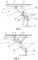
- the articulated frame 10 of the lifting and lowering device 2 could be guided in a guide device 5, as shown in FIG. 5.
- a construction element 21 can be guided in a guide device 5.
- two rods 7 are rotatably arranged via joints 9, which are connected at their opposite ends via a further rod-shaped construction element 15.
- the construction elements 7, 15, 21 thus again form a parallelogram-shaped articulated frame 10.
- a vehicle guide piece 4 is arranged on the construction element 15, the construction element 15 naturally also being part of the vehicle guide piece 4.
- Another rod-shaped construction element 13 is articulated at one end to the ceiling structure 3 and at the other end at the connection point V with a rod 7 of the articulated frame 10.
- this lifting and lowering device 2 can in turn be considered very simply.
- This exemplary embodiment essentially represents a further development of the lifting and lowering device 2 according to FIG. 2, and it is thereby achieved in particular that the predetermined position of the vehicle guide piece 4, here the horizontal, is retained in every lifting position. Otherwise, what has already been said for FIGS. 1 and 2 applies analogously.
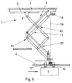
- FIG. 6 shows an embodiment variant in which the lifting and lowering device 2 is included a conventional, known scissor mechanism 22 has been expanded.
- the kinematics of the lifting and lowering device 2 can by the design and connection of the construction elements and the Guide device 5, as detailed above, can be influenced very easily.
- a lifting station 1 according to the invention could of course also be equipped with more than one lifting or lowering device 2.
- two rods 13 lying next to one another, viewed in the direction of travel, or two articulated frames 10 and 11 could be provided between which the guide element 7 is arranged.
- Such an embodiment would have the advantage that it would be essentially torque-free due to the symmetrical arrangement of the construction elements. But of course all other possible kinematic configurations are also encompassed by this invention.
- a lifting station 1 as described above can e.g. in production lines of the automotive industry Manufacturing of bodies or body parts are used, e.g. in a monorail.
- a plurality of vehicles 1 are located between several work stations, e.g. Welding stations, moving, the movement at different levels can take place.
- the vehicles 6 are fastened along a ceiling Guide device, e.g. a rail, moves.
- vehicle guide piece 4 For precise location fixation when handing over or taking over components to or from Vehicle 6 or when vehicle 6 enters or exits vehicle guide piece 4 centering devices, e.g. Guide pin or mounting pin, be used.
- centering devices e.g. Guide pin or mounting pin.
- the vehicle guide pieces 4 and the vehicles 6 can easily and safely slide into the centering devices.
- the present lifting station 1 there is no lateral deflection when the load torque changes due to the off-center load on the vehicle 6.
- the folding mechanism of the lifting or lowering device 2 also has the advantage that in a simple way supply lines, for example electricity, water, compressed air, etc., of devices on the vehicle guide piece, e.g. Tensioning devices, along the Structural elements of the lifting and lowering device 2 can be guided, wherein these do not need to be specially protected because the construction elements are due to the kinematics are not in the work area and there is a risk of damage to the Lines is therefore low.
- supply lines for example electricity, water, compressed air, etc.
- guide devices 5 constructions not specifically described are used, e.g. a cone, a Sled or a role that are guided in a corresponding rail, or also a slide rod guide, slide guide, etc.
- the lifting and lowering device 2 can also be locked so safe opening is guaranteed.
Landscapes
- Life Sciences & Earth Sciences (AREA)
- Engineering & Computer Science (AREA)
- Geology (AREA)
- Mechanical Engineering (AREA)
- Structural Engineering (AREA)
- Carriers, Traveling Bodies, And Overhead Traveling Cranes (AREA)
- Conveying And Assembling Of Building Elements In Situ (AREA)
Abstract
Description
Bisher waren dazu Ausführungen mit Führungssäulen, die jedoch aufwendig, schwer und teuer sind, und Scherenmechanismen, die ein langes Schienenstück erfordern, da auch am Schienenstück eine entsprechende Führung vorgesehen werden muss, bekannt.
Damit erzielt man zum Einen einen besonders einfachen und kompakte Aufbau der Hebestation. Durch die geringe erforderliche Anzahl an Konstruktionselementen kann eine solche Hebestation auch sehr einfach und günstig hergestellt werden.
Trotz der Kompaktheit der Heb- und Senkeinrichtung wird durch die besondere Ausgestaltung der Hub- und Senkeinrichtung eine ausreichende Steifigkeit in und quer zur Transportrichtung des Fahrzeuges sichergestellt.
Außerdem kann durch die Y-förmige Anordnung der Konstruktionselemente der Hub- und Senkeinrichtung auch ein sehr kurzes Schienenstück gehoben werden, da sich die Hüllkurve des Konstruktionselementes beim Heben parabelförmig um die feststehende Fahrzeugführung schmiegt, was die Kompaktheit der Hebestation noch weiter erhöht.
Ist das lange Konstruktionselement das geführte und auch noch doppelt so lange wie das kurze und ist das kurze in der Mitte des langen gelenkig gelagert, ergibt sich eine ausgesprochen vorteilhafte Ausführung einer Hebestation, da dann sichergestellt ist, dass das Fahrzeugführungsstück rein vertikal bewegt wird, wodurch eine einfache Positionierung des Fahrzeugführungsstückes ermöglicht wird.
Bei einem Längenverhältnis zwischen Führungselement und einem Konstruktionselement der Gelenkrahmen von 2:1 und einer gelenkigen Verbindung zwischen Gelenkrahmen und Führungselement in der Mitte des Führungselementes wird außerdem eine rein vertikale Bewegung des Fahrzeugführungsstückes gewährleistet.
Die Hub- und Senkeinrichtung 2 der Hebestation 1 ist dazu an einer Deckenkonstruktion 3 hängend angeordnet und ist mit einem frei beweglichen Fahrzeugführungsstück 4 verbunden, das mittels der Hub- und Senkeinrichtung 2 in unterschiedliche Hebepositionen 8a, 8b gehoben werden kann. Dazu ist beispielsweise an der Deckenkonstruktion 3 ein Hubantrieb 18, hier ein Seilzug, vorgesehen. Das Seil 19 des Hubantriebs 18 ist am Hubangriffspunkt H mit dem Fahrzeugführungsstück 4 verbunden. Damit wird die Heb- und Senkeinrichtung 2 durch das Eigengewicht und den Hubantrieb 18 kontrolliert abgesenkt und mittels dem Hubantrieb 18 angehoben. Jeder andere Hubantrieb 18, wie beispielsweise ein Kettenantrieb, Gewindestangenantrieb, Zahnstangenantrieb, Hydraulikzylinder, Pneumatikzylinder oder ähnliches wäre natürlich ebenfalls denkbar. Gleichfalls könnte man in bekannter Weise auch ein Gegengewicht vorsehen, um den Hubantrieb 18 zu unterstützen.
Würde der Hubantrieb 18 nicht am Fahrzeugführungsstück 4 angreifen, sondern an einem Konstruktionselement der Hub- und Senkeinrichtung 2, so müssten die Konstruktionselemente der Hub- und Senkeinrichtung 2 die Gewichtskraft des Fahrzeuges 6 einschließlich der transportierten Last und die entstehenden Biegemomente aufnehmen und übertragen.
Das Fahrzeugführungsstück 4 ist, wie am besten in Fig. 1 in der Seitenansicht gesehen in Bewegungsrichtung des Fahrzeuges 6 erkennbar, in dieser Ausgestaltung als U-förmiges Grundelement ausgeführt, an dem die Konstruktionselemente 7, 13, 15 der Heb- und Senkeinrichtung 2 angeordnet sind und an dessen Unterseite ein Teil einer Fahrzeugführung, hier eine I-förmige Schiene, angeordnet ist. Selbstverständlich kann das Fahrzeugführungsstück 4 auch beliebig anders ausgeführt werden.
Jeder der beiden Gelenkrahmen 10, 11 besteht hier aus zwei längeren Stäben 13 und zwei kürzeren Stäben 12, 14, 15, bzw. aus etwas stabähnlichem, als Konstruktionselemente, die natürlich jeweils die gleiche Länge aufweisen müssen, um ein Parallelogramm bilden zu können. Ein erster Gelenkrahmen 10 ist über Konstruktionselemente 13 und einen Stab 15 an den beiden Anlenkpunkten A mit dem Fahrzeugführungsstück 4 verbunden bzw. wird der Stab 15 vom Fahrzeugführungsstück 4 selbst gebildet. An diesen Stab 15 sind über Gelenke 9 zwei weitere Stäbe 13 drehbar gelagert angeordnet, die an der gegenüberliegenden Seite wiederum durch ein Verbindungselement 12, an dem die beiden Stäbe 13 wiederum drehbar gelagert sind, miteinander verbunden sind. Dabei bildet ein Teil des Führungselementes 7, im speziellen der Teil zwischen Verbindungspunkt V und Anlenkpunkt A, einen der beiden Stäbe 13. Das zweite Parallelogramm wird durch ein Konstruktionselement 14 gebildet, das hier als Teil der Deckenkonstruktion 3 ausgebildet ist und an dem wieder zwei Stäbe 13 drehbar gelagert angeordnet sind, die am gegenüberliegenden Ende der Stäbe wiederum über das Verbindungselement 12 gelenkig verbunden sind. Die beiden so, über das Verbindungselement 12 verbundenen Gelenkrahmen 10, 11 sind über einen einzigen Verbindungspunkt V gelenkig mit dem Führungselement 7 verbunden. Das Führungselement 7 weist hier die doppelte Länge wie die Stäbe 13 auf und der Verbindungspunkt V liegt in der Mitte des Führungselementes 7. Aus der Kinematik dieses Anordnung ergibt sich, dass das Fahrzeugführungsstück 4 bei einer Bewegung des Führungspunktes F ausschließlich vertikal bewegt wird und dass, bedingt durch die beiden Gelenkrahmen 10, 11, zusätzlich das Fahrzeugführungsstück 4 in allen Hebepositionen ihre vorgegebene, hier horizontale, Lage beibehält. Werden die Längenverhältnisse der einzelnen Konstruktionselemente 7, 13 der Gelenkrahmen 10, 11 und die Lage des Verbindungspunktes V anders gewählt, ergibt sich unter Umständen keine reine vertikale Bewegung des Anlenkpunktes A mehr. Diese überlagerte horizontale Bewegung könnte man kinematisch, z.B. durch eine geeignete Gestaltung der Führungskurve der Führungseinrichtung 5, ausgleichen.
Gleichfalls wäre es auch denkbar, ein anderes oder mehrere Konstruktionselement(e) in einer oder weiteren Führungseinrichtung(en) zu führen, was die Kinematik der Heb- und Senkeinrichtung 2 ebenfalls verändern würde. Die Auslegung eines solchen kinematischen Systems ist eine Standardaufgabe eines entsprechenden Fachmannes und es wird in der Folge darauf verzichtet näher darauf einzugehen.
Die Hub- und Senkeinrichtung 2 besteht in diesem speziellen Beispiel aus zwei Konstruktionselementen 7, 13, die hier stabförmig ausgebildet sind und die über Gelenke 9 drehbar miteinander verbunden sind. Der längere Stab ist hier als Führungselement 7 ausgeführt, dessen einer Führungseinrichtung 5 zugeordnetes Ende in dieser Führungseinrichtung 5 geführt bewegbar und drehbar gelagert ist. Dieses Ende des Führungselementes 7 ist über ein weiteres Gelenk 9 drehbar mit einem Element der Führungseinrichtung 5 verbunden und der damit vorgegebene Führungspunkt F kann daher ausschließlich entlang einer durch die Führungseinrichtung 5 vorgegebenen Kurve bewegt werden, in diesem speziellen Beispiel eine lineare Führung. Das entgegengesetzte Ende des Führungselementes 7 ist am Anlenkpunkt A mit dem Fahrzeugführungsstück 4 verbunden. Der kurze Stab 13 der Hub- und Senkeinrichtung 2 ist mit einem Ende über ein Gelenk 9 an der Deckenkonstruktion 3 drehbar gelagert und mit dem anderen Ende wiederum über ein Gelenk 9 zwischen den beiden Enden des Führungselementes 7 am Führungselement 7 drehbar gelagert. In einer gehobenen bzw. gesenkten Position sind die Konstruktionselemente 7, 13 hier also immer Y-förmig angeordnet.
Die Längen des Stabes 13 und des Führungselementes 7 sind im Beispiel nach Fig. 2 so gewählt, dass das Führungselement 7 doppelt so lang ist, wie die Länge des kurzen Stabes 13 und der Verbindungspunkt V zwischen Führungselement 7 und dem kurzen Stab 13 ist in der Mitte des Führungselementes 7 gewählt. Aus dieser speziellen Gestaltung ergeben sich besondere kinematische Vorteile. Wie man sich kinematisch leicht überlegen kann, wird das Fahrzeugführungsstück 4 bei dieser Anordnung bei einer Verschiebung des Führungspunktes F entlang der Führungseinrichtung 5 im Wesentlichen senkrecht gehoben oder abgesenkt und es kommt zu keiner horizontalen Verschiebung des Fahrzeugführungsstückes 4, wie durch die strichlierte Linie in Fig. 2, die eine weitere Hebeposition zeigt, angedeutet wird.
Bei einer starren Verbindung zwischen Führungselement 7 und Fahrzeugführungsstück 4 würde sich lediglich das Fahrzeugführungsstück 4 verschwenken, maximal um 90°. Diese Verschwenkung könnte man entweder als gegeben hinnehmen, oder man könnte auch einen gewissen Ausgleich der Lage des Fahrzeugführungsstückes 4 vorsehen. Z.B. könnten man eine drehbare Verbindung zwischen Führungselement 7 und Fahrzeugführungsstück 4 am Anlenkpunkt A vorsehen und die Verschwenkung durch eine geeignete Vorrichtung, wie z.B. ein Schrittmotor, Balancegewichte, oder ähnliches, ausgleichen, sodass immer eine erwünschte Lage, z.B. eine horizontale Lage, des Fahrzeugführungsstückes 4 gewährleistet ist.
Bei einer gelenkigen Verbindung zwischen Führungselement 7 und Fahrzeugführungsstück 4, wie in Fig. 2 dargestellt, würde sich das Fahrzeugführungsstück 4 natürlich so ausrichten, dass der Schwerpunkt des Fahrzeugführungsstückes 4 einschließlich dem nicht dargestellten Fahrzeug 6 auf einer senkrechten Linie durch den Anlenkpunkt A zu liegen kommt. Ordnet man das Fahrzeug 6 auf dem Fahrzeugführungsstück 4 entsprechend an, so kann man sehr einfach eine horizontale Lage des Fahrzeugführungsstückes 4 erzwingen. Natürlich könnten die Längenverhältnisse der Konstruktionselemente 7, 13 und die Lage des Verbindungspunktes V auch anders gewählt werden, wobei sich dann unter Umständen keine rein vertikale Bewegung des Anlenkpunktes A mehr ergibt. Diese überlagerte horizontale Bewegung könnte man kinematisch jedoch z.B. durch eine geeignete Gestaltung der Führungskurve der Führungseinrichtung 5 ausgleichen. Die Auslegung eines solchen kinematischen Systems, wie z.B. eine hinlänglich bekannte Kulissensteuerung, gehört in das Standardwissen eines entsprechenden Fachmannes und es wird daher nicht näher darauf eingegangen.
Ist hingegen das Ende des Stabes 13 an der Deckenkonstruktion 3 in einer Führungseinrichtung 5 geführt und dafür das Führungselement 7 fest an der Deckenkonstruktion 3 drehbar gelagert, dann ergäbe sich immer eine vertikale und horizontale Bewegung des Anlenkpunktes A, hier natürlich eine kreisbogenförmige. Eine solche Anordnung wäre jedoch natürlich genauso denkbar.
Es wäre aber natürlich auch denkbar beide Stäbe 7, 13 in einer Führungseinrichtung 5 zu führen.
Aus der Kinematik kann sehr einfach entnommen werden, dass sich der Anlenkpunkt A bei einer Hubbewegung hier entlang einer elliptischen Bahn bewegen würde. Durch eine entsprechende Gestaltung der Führungseinrichtung 5 und/oder der Führungseinrichtung 20 könnte man selbstverständlich wieder eine im Wesentlichen vertikale Bewegung des Fahrzeugführungsstückes 4 erreichen.
Bezüglich einer eventuellen Verdrehung des Fahrzeugführungsstückes 4 beim Heben oder Senken gilt das bereits weiter oben gesagte.
Würde man den Anlenkpunkt A und den Verbindungspunkt V in einem Punkt zusammenfallen lassen, also direkt den Anlenkpunkt A in der vertikalen Führungseinrichtung 20 führen, so würde man hier sehr einfach eine vertikale Bewegung des Fahrzeugführungsstückes 4 erreichen.
Um eine kompaktere Bauweise zu erreichen, könnte die vertikale Führungseinrichtung 20 beispielsweise auch teleskopartig ausgeführt sein, d.h., dass die Führungseinrichtung 20, je nach Hubposition mehr oder weniger weit ausgefahren wird.
Die Kinematik dieser Heb- und Senkeinrichtung 2 kann wiederum sehr einfach überlegt werden. Im Wesentlichen stellt dieses Ausführungsbeispiel eine Weiterentwicklung der Heb- und Senkeinrichtung 2 nach Fig. 2 dar und es wird damit insbesondere erreicht, dass die vorgegebene Lage des Fahrzeugführungsstückes 4, hier die Horizontale, in jeder Hubposition erhalten bleibt. Ansonsten gilt das bereits zur Fig. 1 und 2 gesagte analog.
Genauso wäre es auch denkbar die Hub- bzw. Senkeinrichtung 2 im Rahmen der Erfindung anders zu gestalten. Beispielsweise könnten zwei in Fahrtrichtung betrachtet nebeneinanderliegende Stäbe 13, oder zwei Gelenkrahmen 10 und 11 vorgesehen werden zwischen denen das Führungselement 7 angeordnet ist. Eine solche Ausgestaltung hätte den Vorteil, dass diese aufgrund der symmetrischen Anordnung der Konstruktionselemente im Wesentlichen momentenfrei wäre. Aber es sind natürlich auch alle anderen mögliche kinematische Ausgestaltungen durch diese Erfindung umfasst.
Das Gleiche gilt auch für das Ende des Konstruktionselementes. Mit Ende ist nicht unbedingt das tatsächliche Ende des Konstruktionselementes zu verstehen, sondern man bezieht sich damit wiederum auf einen Drehpunkt. Das Konstruktionselement kann dabei natürlich über den Drehpunkt hinausragen.
Es können natürlich ohne Einschränkungen beliebige Konstruktionselemente, wie Stäbe, Träger, Rohre, Formrohre, etc. verwendet werden, die natürlich auch beliebig geformt sein könnten, wie z.B. gerade, gekrümmt, etc.
Claims (39)
- Hebestation einer Hängebahn, vorzugsweise eine Elektrohängebahn, mit einer an einer Deckenkonstruktion (3) befestigten hängenden Heb- bzw. Senkeinrichtung (2) zum Heben und/oder Senken eines Fahrzeugführungsstückes (4), welches an der Heb- bzw. Senkeinrichtung (2) befestigt ist, zumindest bestehend aus einer Anzahl im Wesentlichen starrer, vorzugsweise langgestreckter, Konstruktionselemente (7, 13), die durch zumindest ein Gelenk (9) miteinander verbunden sind und mit der das Fahrzeugführungsstück (4), gegebenenfalls mit einem Fahrzeug (6) der Hängebahn, von einer ersten Hebeposition auf zumindest eine weitere Hebeposition hebbar ist, dadurch gekennzeichnet, dass zumindest zwei Konstruktionselemente (7, 13) der Heb- bzw. Senkeinrichtung (2) zumindest in einer Hubposition Y-förmig angeordnet sind.
- Hebestation nach Anspruch 1, dadurch gekennzeichnet, dass eine erste Hebeposition eine erste Fahrzeugführung (8a) und eine zweite Hebeposition eine bezüglich der ersten Fahrzeugführung (8a) tiefer oder höher liegende zweite Fahrzeugführung (8b) ist.
- Hebestation nach Anspruch 1, dadurch gekennzeichnet, dass eine erste Hebeposition eine Fahrzeugführung (8a) und eine zweite Hebeposition eine Bauteilübernahmeposition (8c), bzw. umgekehrt, ist und gegebenenfalls eine dritte Hebeposition, vorzugsweise eine weitere Fahrzeugführung (8b), vorgesehen ist.
- Hebestation nach einem der Ansprüche 1 bis 3, dadurch gekennzeichnet, dass ein Hubantrieb vorgesehen ist und dass der Hubangriffspunkt (H) des Hubantriebes (18) am Fahrzeugführungsstück (4) oder in der Nähe eines Anlenkpunktes (A) des Fahrzeugführungsstückes (4) an einem mit dem Fahrzeugführungsstück (4) verbundenen Konstruktionselement (7, 13), vorzugsweise im Bereich von 0 bis 50%, insbesondere im Bereich von 0 bis 25%, der Länge des längsten mit dem Fahrzeugführungsstück (4) verbundenen Konstruktionselementes, angeordnet ist.
- Hebestation nach einem der Ansprüche 1 bis 4, dadurch gekennzeichnet, dass ein Ende eines ersten Konstruktionselementes (13) an der Deckenkonstruktion (3) drehbar gelagert angeordnet ist und das andere Ende dieses Konstruktionselementes (13) zwischen den beiden Enden eines zweiten Konstruktionselementes (7) an diesem drehbar gelagert angeordnet ist.
- Hebestation nach einem der Ansprüche 1 bis 5, dadurch gekennzeichnet, dass zumindest ein Konstruktionselement (7, 13) in einer Führungseinrichtung (5) geführt bewegbar und drehbar gelagert angeordnet ist.
- Hebestation nach einem der Ansprüche 1 bis 6, dadurch gekennzeichnet, dass ein erstes Konstruktionselement (7) als Führungselement ausgeführt ist, wobei ein Ende dieses Führungselementes (7) in der Führungseinrichtung (5) geführt bewegbar und drehbar gelagert angeordnet ist und das andere Ende des Führungselementes (7) mit dem Fahrzeugführungsstück (4) und/oder mit einem zweiten Konstruktionselement (13) verbunden ist.
- Hebestation nach einem der Ansprüche 1 bis 7, dadurch gekennzeichnet, dass eines der Konstruktionselemente (7, 13) länger als das andere Konstruktionselement ausgeführt ist.
- Hebestation nach Anspruch 8, dadurch gekennzeichnet, dass das längere Konstruktionselement im Wesentlichen die doppelte Länge des kurzen Konstruktionselementes aufweist.
- Hebestation nach Anspruch 8 oder 9, dadurch gekennzeichnet, dass das kurze Konstruktionselement im Wesentlich in der Mitte des langen Konstruktionselementes mit dem langen Konstruktionselement gelenkig verbunden ist.
- Hebestation nach einem der Ansprüche 8 bis 10, dadurch gekennzeichnet, dass das Führungselement (7) das lange Konstruktionselement ist.
- Hebestation nach einem der Ansprüche 6 bis 11, dadurch gekennzeichnet, dass die Führungseinrichtung (5) derart ausgeführt ist, dass durch die Kinematik der Heb- bzw. Senkeinrichtung (2) das mit dem Fahrzeugsführungsstück (4) verbundene Ende des Führungselementes (7) im Wesentlichen vertikal bewegbar ist.
- Hebestation nach einem der Ansprüche 1 bis 4, dadurch gekennzeichnet, dass die Heb- bzw. Senkeinrichtung (2) mit zumindest einen mehrgliedrigen Gelenkrahmen (10, 11), bestehend aus einer Anzahl gelenkig miteinander verbundener Konstruktionselemente (12, 13), und einem Führungselement (7) ausgeführt ist.
- Hebestation nach Anspruch 13, dadurch gekennzeichnet, dass zumindest ein, vorzugsweise jeder, der mehrgliedrigen Gelenkrahmen (10, 11) als Parallelogramm, bestehend aus vier gelenkig miteinander verbundenen Konstruktionselementen (12, 13, 14, 15), von welchem jeweils zwei Konstruktionselemente (13, 12 und 15, 12 und 14) in allen Hebepositionen im Wesentlichen parallel angeordnet sind, ausgeführt ist.
- Hebestation nach Anspruch 13 oder 14, dadurch gekennzeichnet, dass ein Konstruktionselement eines ersten Gelenkrahmens gleichzeitig auch ein Konstruktionselement eines zweiten Gelenkrahmens ist und dieses Verbindungselement (12) die Verbindung zwischen den beiden Gelenkrahmen (10, 11) bildet.
- Hebestation nach Anspruch 15, dadurch gekennzeichnet, dass ein Konstruktionselement (14) starr mit der Deckenkonstruktion (3) verbunden ist bzw. von der Deckenkonstruktion (3) gebildet wird und an diesem Konstruktionselement (14) die Enden zweier weiterer Konstruktionselemente (13) drehbar gelagert angeordnet sind, wobei die beiden anderen Enden dieser Konstruktionselemente (13) am Verbindungselement (12) drehbar gelagert angeordnet sind und diese vier Konstruktionselemente (12, 13, 14) einen ersten Gelenkrahmen (11) bilden.
- Hebestation nach Anspruch 15 oder 16, dadurch gekennzeichnet, dass ein Konstruktionselement (15) starr mit dem Fahrzeugführungsstück (4) verbunden ist bzw. vom Fahrzeugführungsstück (4) gebildet wird und an diesem Konstruktionselement (15) die Enden zweier weiterer Konstruktionselemente (13) drehbar gelagert angeordnet sind, wobei die beiden anderen Enden dieser Konstruktionselemente (13) am Verbindungselement (12) drehbar gelagert angeordnet sind und diese vier Konstruktionselemente (12, 13, 15) einen zweiten Gelenkrahmen (10) bilden.
- Hebestation nach einem der Ansprüche 13 bis 17, dadurch gekennzeichnet, dass ein Ende des Führungselementes (7) in der Führungseinrichtung (5) geführt bewegbar und drehbar angeordnet ist und das andere Ende des Führungselementes (7) mit einem Konstruktionselement (12, 13) eines Gelenkrahmens (10, 11) bzw. mit dem Fahrzeugführungsstück (4) verbunden ist.
- Hebestation nach Anspruch 18, dadurch gekennzeichnet, dass das Führungselement (7) gleichzeitig zumindest teilweise ein Konstruktionselement (13) eines Gelenkrahmens (10, 11) ist.
- Hebestation nach einem der Ansprüche 13 bis 19, dadurch gekennzeichnet, dass das Führungselement (7) länger als das längste Konstruktionselement der beiden Gelenkrahmen (10, 11) ausgeführt ist.
- Hebestation nach Anspruch 20, dadurch gekennzeichnet, dass das Führungselement (7) doppelt so lang wie das längste Konstruktionselement des Gelenkrahmens (10, 11) ausgeführt ist.
- Hebestation nach einem der Ansprüche 19 bis 21, dadurch gekennzeichnet, dass ein Ende des Verbindungselementes (12) zwischen den beiden Enden des Führungselementes (7) am Führungselement (7) drehbar gelagert angeordnet ist.
- Hebestation nach Anspruch 22, dadurch gekennzeichnet, dass ein Ende des Verbindungselementes (12) zwischen den beiden Enden im Wesentlichen in der Mitte des Führungselementes (7) am Führungselement (7) drehbar gelagert angeordnet ist.
- Hebestation nach einem der Ansprüche 1 bis 4, dadurch gekennzeichnet, dass zumindest ein erstes Konstruktionselement (20) der Heb- bzw. Senkeinrichtung (2) als Führungseinrichtung ausgeführt ist, wobei zumindest ein vorbestimmbarer erster Punkt (V) eines zweiten als Führungselement vorgesehenen Konstruktionselementes (7) in dieser Führungseinrichtung (20) geführt bewegbar und drehbar gelagert angeordnet ist.
- Hebestation nach Anspruch 24, dadurch gekennzeichnet, dass die Heb- bzw. Senkeinrichtung (2) mit zumindest einen mehrgliedrigen Gelenkrahmen (10), bestehend aus einer Anzahl gelenkig miteinander verbundener Konstruktionselemente (13), und einem Führungselement (7) ausgeführt ist, wobei das Führungselement (7) gegebenenfalls Teil des Gelenkrahmens (10) ist.
- Hebestation nach Anspruch 25, dadurch gekennzeichnet, dass das Führungselement (7) gelenkig mit dem Gelenksrahmen (10) verbunden ist.
- Hebestation nach Anspruch 24, 25 oder 26, dadurch gekennzeichnet, dass ein vorbestimmbarer zweiter Punkt (F) des Führungselementes (7) in einer zweiten Führungseinrichtung (5) geführt bewegbar und drehbar gelagert angeordnet ist.
- Hebestation nach einem der Ansprüche 24 bis 27, dadurch gekennzeichnet, dass das Führungselement (7) und/oder der Gelenkrahmen (10) mit dem Fahrzeugführungsstück (4) verbunden ist.
- Hebestation nach einem der Ansprüche 24 bis 28, dadurch gekennzeichnet, dass eine erste Führungseinrichtung (20) im Wesentlichen vertikal oder schräg und eine zweite Führungseinrichtung (5) im Wesentlichen horizontal oder schräg ausgerichtet ist.
- Hebestation nach einem der Ansprüche 1 bis 4, dadurch gekennzeichnet, dass zumindest ein erster Teil der Hub- und Senkeinrichtung (2) als hinlänglich bekannter X-förmiger Scherenmechanismus (22) ausgebildet ist und daran ein aus zumindest zwei Konstruktionselementen aufgebauter Y-förmiger zweiter Teil (23) der Hub- und Senkeinrichtung (2) anschließt.
- Hebestation nach Anspruch 30, dadurch gekennzeichnet, dass zumindest ein Konstruktionselement, vorzugsweise ein Konstruktionselement des X-förmigen Scherenmechanismus (22), der Hub- und Senkeinrichtung (2) in einer Führungseinrichtung (5) geführt bewegbar gelagert ist.
- Hebestation nach Anspruch 30 oder 31, dadurch gekennzeichnet, dass eine Anzahl der Konstruktionselemente als parallelogrammförmige Gelenkrahmen (10, 11) ausgebildet sind.
- Hebestation nach Anspruch 32, dadurch gekennzeichnet, dass ein erster Gelenkrahmen (10) mit dem Fahrzeugführungsstück (4) verbunden ist.
- Hebestation nach Anspruch 32 oder 33, dadurch gekennzeichnet, dass ein zweiter Gelenkrahmen (11) Teil des X-förmigen Scherenmechanismus (22) ist.
- Hebestation nach einem der Ansprüche 1 bis 34, dadurch gekennzeichnet, dass die Führungseinrichtungen (5, 20) an der Deckenkonstruktion (3) angeordnet sind.
- Hebestation nach einem der Ansprüche 1 bis 35, dadurch gekennzeichnet, dass die Konstruktionselemente (13, 14, 15), das Verbindungselement (12) und/oder das Führungselement (7) zumindest teilweise als Stäbe ausgeführt sind, die vorzugsweise aus Rohren, Formrohren, oder Profilen gebildet sind.
- Hebestation nach einem der Ansprüche 1 bis 36, dadurch gekennzeichnet, dass die Führungseinrichtungen (5, 20) zumindest teilweise als lineare Führung ausgeführt sind.
- Hebestation nach einem der Ansprüche 4 bis 37, dadurch gekennzeichnet, dass der Hubantrieb (18) als Seilantrieb, Gurtantrieb, Kettenantrieb, Gewindestangenantrieb, Zahnstangenantrieb, Hydraulikzylinder oder Pneumatikzylinder ausgeführt ist.
- Hebestation nach einem der Ansprüche 1 bis 38, dadurch gekennzeichnet, dass in Bewegungsrichtung des Fahrzeuges (6) der Hängebahn (1) zu beiden Seiten des Fahrzeuges (6) zumindest je eine Hub- und Senkeinrichtung (2) angeordnet ist.
Applications Claiming Priority (2)
| Application Number | Priority Date | Filing Date | Title |
|---|---|---|---|
| AT2392003 | 2003-02-17 | ||
| AT2392003 | 2003-02-17 |
Publications (2)
| Publication Number | Publication Date |
|---|---|
| EP1447372A2 true EP1447372A2 (de) | 2004-08-18 |
| EP1447372A3 EP1447372A3 (de) | 2004-11-03 |
Family
ID=32660439
Family Applications (1)
| Application Number | Title | Priority Date | Filing Date |
|---|---|---|---|
| EP04002031A Withdrawn EP1447372A3 (de) | 2003-02-17 | 2004-01-30 | Hebestation einer Hängebahn |
Country Status (1)
| Country | Link |
|---|---|
| EP (1) | EP1447372A3 (de) |
Cited By (3)
| Publication number | Priority date | Publication date | Assignee | Title |
|---|---|---|---|---|
| US10106378B2 (en) | 2015-11-03 | 2018-10-23 | General Electric Company | System and method for lifting with load moving machine |
| CN113683032A (zh) * | 2021-09-06 | 2021-11-23 | 奇点变幻科技(天津)有限公司 | 一种连杆式升降装置 |
| US20240228246A1 (en) * | 2023-01-05 | 2024-07-11 | Nexion S.P.A. | Vehicle lift and a method for lifting vehicles |
Family Cites Families (11)
| Publication number | Priority date | Publication date | Assignee | Title |
|---|---|---|---|---|
| US2435755A (en) * | 1946-02-20 | 1948-02-10 | Charles H Schimpff | Displaying and dispensing apparatus |
| DE1816065U (de) * | 1956-09-05 | 1960-08-04 | Demag Ag | Huettenkran. |
| SU1504177A1 (ru) * | 1987-08-18 | 1989-08-30 | Проектно-Конструкторское Бюро Производственного Объединения "Электроприбор" | Кран-штабелер |
| US5366203A (en) * | 1989-07-31 | 1994-11-22 | Safety Lock And Lift, Ltd. | Projector ceiling lift |
| JPH0952604A (ja) * | 1995-08-11 | 1997-02-25 | Yasutsugu Yamazaki | 倉庫内の収容物自動出入れシステム |
| JPH0989068A (ja) * | 1995-09-20 | 1997-03-31 | Hitachi Cable Ltd | 昇降装置 |
| JP3287447B2 (ja) * | 1996-03-22 | 2002-06-04 | 東光電気株式会社 | 昇降装置 |
| JPH1088992A (ja) * | 1996-09-18 | 1998-04-07 | Konishizaki Kk | 巻上装置 |
| DE19643347A1 (de) * | 1996-10-21 | 1998-04-23 | Andreas Zentner | Vorrichtung zum Heben und Absenken von Lasten |
| DE29824302U1 (de) * | 1998-05-05 | 2001-06-28 | Va Tech Transport- Und Montagesysteme Gmbh & Co, Linz | Transportfahrzeug für eine Elektro-Hängebahn |
| JP2001146384A (ja) * | 1999-11-19 | 2001-05-29 | Central Motor Co Ltd | 搬送システム |
-
2004
- 2004-01-30 EP EP04002031A patent/EP1447372A3/de not_active Withdrawn
Cited By (4)
| Publication number | Priority date | Publication date | Assignee | Title |
|---|---|---|---|---|
| US10106378B2 (en) | 2015-11-03 | 2018-10-23 | General Electric Company | System and method for lifting with load moving machine |
| CN113683032A (zh) * | 2021-09-06 | 2021-11-23 | 奇点变幻科技(天津)有限公司 | 一种连杆式升降装置 |
| US20240228246A1 (en) * | 2023-01-05 | 2024-07-11 | Nexion S.P.A. | Vehicle lift and a method for lifting vehicles |
| US12365568B2 (en) * | 2023-01-05 | 2025-07-22 | Nexion S.P.A. | Vehicle lift and a method for lifting vehicles |
Also Published As
| Publication number | Publication date |
|---|---|
| EP1447372A3 (de) | 2004-11-03 |
Similar Documents
| Publication | Publication Date | Title |
|---|---|---|
| EP0983897B1 (de) | Hebevorrichtung | |
| EP0593803A1 (de) | Vorrichtung zum Positionieren von Lasten | |
| EP0501254B1 (de) | Scherenhubtisch | |
| DE112019004917T5 (de) | Faltbarer Traversenauslegerabschnitt, Traversenausleger und Kran | |
| WO2003008266A1 (de) | Auftriebsklappen-mechanismus | |
| EP1240071B1 (de) | Hebevorrichtung mit einer führung für lasten | |
| DE202012002832U1 (de) | Fahrzeuglift mit Vorspanneinrichtung | |
| DE8605875U1 (de) | Montageeinrichtung für Karosserieteile von Kraftfahrzeugen | |
| EP2882634B1 (de) | Überflurfördereinrichtung mit säulenportalen | |
| EP4466217A1 (de) | Lastausgleichsvorrichtung für eine hubapplikation mit einem zu hebenden bzw. zu senkenden gegenstand | |
| EP1340709B1 (de) | Transportanlage zum Transport von Bauteilen | |
| DE10106193B4 (de) | Hubeinheit | |
| EP1378480A1 (de) | Transportfahrzeug zum Transport von Bauteilen | |
| EP2502873A1 (de) | Regalbediengerät | |
| DE102020208430B4 (de) | Schmiedemaschinen-Belade- und -Entladevorrichtung | |
| EP3924285B1 (de) | Aufzugsystem | |
| DE3442940A1 (de) | Hebetisch | |
| EP0054678B1 (de) | Vorrichtung zum Abstellen mehrerer Fahrzeuge übereinander | |
| DE2856350C2 (de) | Fahrzeug zum wahlweisen Transport von Stückgut oder Coils | |
| EP0267413B1 (de) | Schrägaufzug, insbesondere Material- oder Personenaufzug | |
| AT411459B (de) | Hubantrieb | |
| DE102005024289A1 (de) | Scherenhubtisch | |
| WO2009090087A1 (de) | Hubvorrichtung | |
| DE1431892B1 (de) | Im gleichgewicht bleibende trag und einstellvorrichtung | |
| EP1293420A2 (de) | Durch eine Steuerkurve gesteuerter Hubtisch |
Legal Events
| Date | Code | Title | Description |
|---|---|---|---|
| PUAI | Public reference made under article 153(3) epc to a published international application that has entered the european phase |
Free format text: ORIGINAL CODE: 0009012 |
|
| AK | Designated contracting states |
Kind code of ref document: A2 Designated state(s): AT BE BG CH CY CZ DE DK EE ES FI FR GB GR HU IE IT LI LU MC NL PT RO SE SI SK TR |
|
| AX | Request for extension of the european patent |
Extension state: AL LT LV MK |
|
| PUAL | Search report despatched |
Free format text: ORIGINAL CODE: 0009013 |
|
| AK | Designated contracting states |
Kind code of ref document: A3 Designated state(s): AT BE BG CH CY CZ DE DK EE ES FI FR GB GR HU IE IT LI LU MC NL PT RO SE SI SK TR |
|
| AX | Request for extension of the european patent |
Extension state: AL LT LV MK |
|
| AKX | Designation fees paid | ||
| REG | Reference to a national code |
Ref country code: DE Ref legal event code: 8566 |
|
| STAA | Information on the status of an ep patent application or granted ep patent |
Free format text: STATUS: THE APPLICATION IS DEEMED TO BE WITHDRAWN |
|
| 18D | Application deemed to be withdrawn |
Effective date: 20050504 |