EP1447384A1 - Anlage zur Entfernung und Deaktivierung von Organismen im Ballastwasser - Google Patents
Anlage zur Entfernung und Deaktivierung von Organismen im Ballastwasser Download PDFInfo
- Publication number
- EP1447384A1 EP1447384A1 EP04000485A EP04000485A EP1447384A1 EP 1447384 A1 EP1447384 A1 EP 1447384A1 EP 04000485 A EP04000485 A EP 04000485A EP 04000485 A EP04000485 A EP 04000485A EP 1447384 A1 EP1447384 A1 EP 1447384A1
- Authority
- EP
- European Patent Office
- Prior art keywords
- pump
- hydrocyclones
- filter
- filter device
- water
- Prior art date
- Legal status (The legal status is an assumption and is not a legal conclusion. Google has not performed a legal analysis and makes no representation as to the accuracy of the status listed.)
- Granted
Links
- XLYOFNOQVPJJNP-UHFFFAOYSA-N water Substances O XLYOFNOQVPJJNP-UHFFFAOYSA-N 0.000 title claims abstract description 45
- 239000003139 biocide Substances 0.000 claims abstract description 16
- 230000003115 biocidal effect Effects 0.000 claims abstract description 15
- 239000011148 porous material Substances 0.000 claims abstract 2
- 230000003068 static effect Effects 0.000 claims description 10
- 230000005484 gravity Effects 0.000 claims description 8
- 238000000926 separation method Methods 0.000 claims description 8
- 238000011144 upstream manufacturing Methods 0.000 claims description 5
- 238000011001 backwashing Methods 0.000 claims description 4
- 230000007797 corrosion Effects 0.000 claims description 4
- 238000005260 corrosion Methods 0.000 claims description 4
- 238000006073 displacement reaction Methods 0.000 claims description 3
- 230000009849 deactivation Effects 0.000 claims description 2
- 238000009434 installation Methods 0.000 claims 5
- 239000007787 solid Substances 0.000 claims 1
- 238000001914 filtration Methods 0.000 abstract description 4
- 239000011362 coarse particle Substances 0.000 abstract 1
- 244000005700 microbiome Species 0.000 abstract 1
- 230000003641 microbiacidal effect Effects 0.000 description 8
- 229940124561 microbicide Drugs 0.000 description 7
- 239000002855 microbicide agent Substances 0.000 description 7
- JTJMJGYZQZDUJJ-UHFFFAOYSA-N phencyclidine Chemical class C1CCCCN1C1(C=2C=CC=CC=2)CCCCC1 JTJMJGYZQZDUJJ-UHFFFAOYSA-N 0.000 description 7
- 238000002156 mixing Methods 0.000 description 6
- 239000000126 substance Substances 0.000 description 6
- 238000002347 injection Methods 0.000 description 4
- 239000007924 injection Substances 0.000 description 4
- 239000000645 desinfectant Substances 0.000 description 3
- 239000002245 particle Substances 0.000 description 3
- MHAJPDPJQMAIIY-UHFFFAOYSA-N Hydrogen peroxide Chemical compound OO MHAJPDPJQMAIIY-UHFFFAOYSA-N 0.000 description 2
- 241001465754 Metazoa Species 0.000 description 2
- KFSLWBXXFJQRDL-UHFFFAOYSA-N Peracetic acid Chemical compound CC(=O)OO KFSLWBXXFJQRDL-UHFFFAOYSA-N 0.000 description 2
- 244000052616 bacterial pathogen Species 0.000 description 2
- 230000000694 effects Effects 0.000 description 2
- 230000007257 malfunction Effects 0.000 description 2
- 238000000034 method Methods 0.000 description 2
- 239000000203 mixture Substances 0.000 description 2
- 239000008213 purified water Substances 0.000 description 2
- 230000005855 radiation Effects 0.000 description 2
- 239000013535 sea water Substances 0.000 description 2
- 241000251468 Actinopterygii Species 0.000 description 1
- 241000894006 Bacteria Species 0.000 description 1
- 206010010774 Constipation Diseases 0.000 description 1
- 241000238557 Decapoda Species 0.000 description 1
- 241000237536 Mytilus edulis Species 0.000 description 1
- 241000700605 Viruses Species 0.000 description 1
- 238000005299 abrasion Methods 0.000 description 1
- 230000001133 acceleration Effects 0.000 description 1
- 238000009530 blood pressure measurement Methods 0.000 description 1
- 230000015556 catabolic process Effects 0.000 description 1
- 238000005524 ceramic coating Methods 0.000 description 1
- 238000006243 chemical reaction Methods 0.000 description 1
- 239000003795 chemical substances by application Substances 0.000 description 1
- 239000011248 coating agent Substances 0.000 description 1
- 238000000576 coating method Methods 0.000 description 1
- 230000001419 dependent effect Effects 0.000 description 1
- 239000000706 filtrate Substances 0.000 description 1
- 239000007788 liquid Substances 0.000 description 1
- 239000000463 material Substances 0.000 description 1
- 235000020638 mussel Nutrition 0.000 description 1
- 150000007524 organic acids Chemical class 0.000 description 1
- 235000005985 organic acids Nutrition 0.000 description 1
- 230000001590 oxidative effect Effects 0.000 description 1
- 230000000149 penetrating effect Effects 0.000 description 1
- 238000009420 retrofitting Methods 0.000 description 1
- 238000001223 reverse osmosis Methods 0.000 description 1
- 239000013049 sediment Substances 0.000 description 1
- 235000013311 vegetables Nutrition 0.000 description 1
Images

Classifications
-
- C—CHEMISTRY; METALLURGY
- C02—TREATMENT OF WATER, WASTE WATER, SEWAGE, OR SLUDGE
- C02F—TREATMENT OF WATER, WASTE WATER, SEWAGE, OR SLUDGE
- C02F1/00—Treatment of water, waste water, or sewage
- C02F1/50—Treatment of water, waste water, or sewage by addition or application of a germicide or by oligodynamic treatment
-
- E—FIXED CONSTRUCTIONS
- E04—BUILDING
- E04G—SCAFFOLDING; FORMS; SHUTTERING; BUILDING IMPLEMENTS OR AIDS, OR THEIR USE; HANDLING BUILDING MATERIALS ON THE SITE; REPAIRING, BREAKING-UP OR OTHER WORK ON EXISTING BUILDINGS
- E04G21/00—Preparing, conveying, or working-up building materials or building elements in situ; Other devices or measures for constructional work
- E04G21/14—Conveying or assembling building elements
- E04G21/16—Tools or apparatus
- E04G21/18—Adjusting tools; Templates
- E04G21/1808—Holders for bricklayers' lines, bricklayers' bars; Sloping braces
- E04G21/1816—Adjustable positioning means between line-holder bars and construction
-
- C—CHEMISTRY; METALLURGY
- C02—TREATMENT OF WATER, WASTE WATER, SEWAGE, OR SLUDGE
- C02F—TREATMENT OF WATER, WASTE WATER, SEWAGE, OR SLUDGE
- C02F1/00—Treatment of water, waste water, or sewage
- C02F1/001—Processes for the treatment of water whereby the filtration technique is of importance
-
- C—CHEMISTRY; METALLURGY
- C02—TREATMENT OF WATER, WASTE WATER, SEWAGE, OR SLUDGE
- C02F—TREATMENT OF WATER, WASTE WATER, SEWAGE, OR SLUDGE
- C02F1/00—Treatment of water, waste water, or sewage
- C02F1/38—Treatment of water, waste water, or sewage by centrifugal separation
-
- C—CHEMISTRY; METALLURGY
- C02—TREATMENT OF WATER, WASTE WATER, SEWAGE, OR SLUDGE
- C02F—TREATMENT OF WATER, WASTE WATER, SEWAGE, OR SLUDGE
- C02F2103/00—Nature of the water, waste water, sewage or sludge to be treated
- C02F2103/008—Originating from marine vessels, ships and boats, e.g. bilge water or ballast water
Definitions
- the invention relates to a system for removing and deactivating Organisms in ballast water according to the preamble of claim 1.
- ballast water ships take the most diverse animal and plant organisms, e.g. Mussels, fish, worms, crabs, bacteria, Viruses and so on that they in foreign areas where these are not native hand in again. These organisms can often be found in their new environment spread quickly because there is a lack of natural enemies. This can make big ecological and / or economic damage are caused.
- Mussels, fish, worms, crabs, bacteria, Viruses e.g. Mussels, fish, worms, crabs, bacteria, Viruses and so on that they in foreign areas where these are not native hand in again.
- These organisms can often be found in their new environment spread quickly because there is a lack of natural enemies. This can make big ecological and / or economic damage are caused.
- ballast water becomes very large Speed or large quantities in the ballast tanks within a very short time promoted. It must be ensured that in the relatively short period of time Ballast water has been largely sterilized.
- the invention has for its object a system for removal and deactivation to create animal and vegetable organisms in ballast water, those when filling or emptying the tank with little effort Takes safety requirements into account. Furthermore, the system according to the invention cause a low outlay on equipment and, for example, simply on ships can be retrofitted.
- the system according to the invention consists of at least two components.
- the one has gravity separation, e.g. a group of hydrocyclones that are connected in parallel, with a control device ensuring that only as much Hydrocyclones are in operation as needed.
- Hydrocyclones are known to have only a limited operating range. Therefore, a control device switches the hydrocyclones on or off according to the delivery rate.
- the hydrocyclones not only significantly reduce the sediment load carried with the water, but also remove a large part of larger organisms, e.g. in a Size of more than 300 ⁇ m.
- the hydrocyclones are designed so that these organisms can be effectively separated, even if their specific weight only is slightly larger than 1.
- hydrocyclones A special feature of the hydrocyclones is that any number can be connected together can be delivered to any user within the scope of their optimum operation Adjust flow rate. Hydrocyclones also have the advantage of being are almost maintenance-free and reliable. They are insensitive to constipation and can be easily and quickly maintained if necessary. After a Embodiment of the invention, they have a corrosion-resistant, wear-resistant Surface on, e.g. in the form of a coating. As a result, the inner walls are in front protected against abrasive and corrosive loads.
- the first feed pump is preferably a centrifugal pump, such as as Ballast water pump is usually in use.
- the underflow of the hydrocyclones connected to a second feed pump which is a first control device is assigned, which measures the flow rate in the underflow line and is dependent a predetermined constant from the number of activated hydrocyclones Flow rate promotes.
- the second feed pump which is preferably a positive displacement pump can be switched in stages of constant flow, each stage being set to a predetermined level Number of hydrocyclones in operation is set.
- a discharge pump in the lower reaches to at least some of the cyclones.
- a control valve arranged to which a second control device is assigned is a predetermined by controlling the flow cross section of the control valve Maintaining pressure in the upstream line.
- This measure too serves the stable operation of the hydrocyclones, which are particularly useful in backwashing operations of the filter comes into play.
- the pressure at the filter drops during of the backwash operation significantly. Nevertheless, the operation of the hydrocyclones to be maintained.
- a filter device arranged after the gravity separation serves for fine filtration and thus for separating parts and germs of smaller dimensions, approximately in the range of 300 ⁇ m to 50 ⁇ m. Organisms that differ due to their geometry and size can not be separated with the filter device, if necessary so damaged that they are undergoing a chemical or other further treatment step are easily accessible.
- the use of a is particularly advantageous Filter device as it is known from DE 4312731.
- Each filter cartridge A filter device having a plurality of filter cartridges has one Layer of superimposed elements made of elastically deformable material on, each of which two adjacent elements form a flow-through gap.
- Each element has one with its wide front surface on its inflow side the flow facing elastically deflectable and elastic in the flow direction deformable lip, the opening edge of which with the opposite fixed opening edge of the adjacent element forms the gap opening.
- One with the current jamming particles penetrating into the stomata practice the stomata narrowing driving force on the opening edge of the lip.
- the hydrocyclones are used in the backwash mode coming cleaned liquid against the downstream side of a filter surface directed, while the upstream side with a backwash pump in one Backwash branch is connected.
- the backwash operation is preferably initiated, if the filter gradually clogs up.
- This case is designed the invention detected by a differential pressure measurement.
- the differential pressure is on predetermined value, the backwashing operation is initiated via the control device.
- the regulation described above in the upper and lower reaches of the cyclones ensures that that the backwash operation has no negative effects on the operation of the hydrocyclones Has.
- Organisms and germs in the water downstream of the filter device become harmless by the last component of the system according to the invention made, preferably by chemical treatment, with an agent which preferably has a short breakdown time and is then biologically harmless.
- a chemical such as a mixture of organic acids such as Peracetic acid, hydrogen peroxide, etc.
- the supply of the chemical is preferably a purely oxidative biocide according to another embodiment of the invention depending on the volume of funding. It goes without saying that, in addition to the chemical treatment step, additionally or alternatively other treatment options are conceivable, for example UV radiation or similar.
- the invention provides a metering device, wherein according to a further embodiment of the invention between the introduction point in the output line of the filter device and an upstream point of Output line, a booster pump is switched, and a metering pump enters the biocide into the outlet line of the booster pump through a nozzle.
- a bypass metering With this bypass metering, a partial stream is removed from the filtered water and put it under increased pressure.
- the injection valve is in this Pressurized water doses the biocide. Because of this admixture, one is already found Premix the biocide with water instead. The premixed water is under Conversion of pressure energy into kinetic energy given in the main stream.
- a static mixer is connected downstream, for an intimate mixing of the microbicide with the one to be treated Water provides.
- the addition of the microbiocide described is done with very low pressure drops. Therefore, the first feed pump is not necessary interpret that an additional pressure drop must be absorbed.
- the individual treatment stages preferably have a bypass, so that at A malfunction or failure of the auxiliary power and a water flow is guaranteed to e.g. to be able to guarantee ship safety.
- the system according to the invention is designed so that it operates almost maintenance-free can be guaranteed and the highest possible operational reliability. It is for New buildings and equally suitable for retrofitting.
- the external dimensions the entire system can be based on the space available, for example on ships. All components come with the usual deck height. The electric one Power requirements are relatively low.
- the system according to the invention is not limited in its application to ships, rather, it can also be used for land systems if the same or similar task exists.
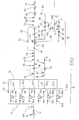
- Component 1 has the stages or components A, B and C.
- the Component A is used for gravity separation of parts in water that are heavier than are water.
- Component B relates to a fine filtration stage.
- Component C relates to the addition of a disinfectant. following position should be given to the individual components.
- the upper reaches of the hydrocyclones 16.1 to 16.6 is connected to a common line 20.
- the lower reaches of the Hydrocyclones 16.1 to 16.6 is connected to a common line 22 Shut-off valves 24.1 to 24.6.
- the line 22 is connected to a line branch 26, in which there is a pressure meter 28, flow meter 30, a second feed pump 32 and a shut-off valve 34 is located. On the function of the described Parts are discussed below.
- the line 20 is connected to a line branch 36, in which a control valve 38 is arranged. Furthermore, a pressure gauge 40 is provided on the line branch 36 the valve 38 and a flow meter 42 connected behind the valve 38. In front of and behind the flow meter 42 are further pressure meters 44 and 46 arranged.
- a check valve 48 with the branch 36 is a backwashable filter device 50 connected.
- an output line 52 of the filter device 50 there are one Control valve 54, a shut-off valve 56, a pressure meter 58 and a flow meter 60 switched.
- a shut-off valve 64 is arranged in a bypass line 62, which is in front of the valve 48 and behind the valve 56 with the inlet or the outlet of the filter device 50 is connected.
- a Shut-off valve 68 In a suction line 66, which is connected to the filter device 50, a Shut-off valve 68, a backwash pump 70, a pressure gauge 72, a control valve 74 and another shut-off valve 76 is arranged.
- a branch line 78 which immediately downstream of the filter device 50 with the Branch outlet line 52 is connected, includes a shut-off valve 80, a booster pump 82, a check valve 84, an injector 86 and a Shut-off valve 88.
- the branch line 78 opens on the downstream side of the flow meter 60 via an injection nozzle 90 into the outlet line 52 a static mixer 92 is arranged in the line 52 of the injection nozzle 90.
- the downstream side of the static mixer 92 is connected to the output line 52 Pressure gauge 54 connected.
- the output line 52 does not lead to one shown tank, for example a ballast tank on a ship.
- a control device controls the individual functions of the described Parts and components that also contain some control loops. Following the function of the system according to Figure 1 will be explained in more detail.
- shut-off valves 12 and 18.1 to 18.6 open and shut-off valve closed 96 feeds the in a bypass line 98 for the hydrocyclones 16.1 to 16.6 Centrifugal pump 10 sea water in the hydrocyclones 16.1 to 16.6.
- the lower reaches of the Hydrocyclones 16.1 to 16.6 is connected to line 26, and the constant Delivery pump, preferably the displacement pump 32 delivers a constant volume from the lower reaches of the hydrocyclones into the sea.
- the number of actually turned on Hydrocyclones 16.1 to 16.6, depend on the demanded delivery rate from, which can also be proportional to the pressure on the downstream side of the Pump 10 can be measured using the pressure gauge 100. With partial filled ballast water tank, the delivery rate is necessarily smaller.
- the second Feed pump 32 delivers a constant amount of water, however the amount depends on the number of activated hydrocyclones 16.1 to 16.6. With the increasing number of switched on hydrocyclones 16.1 to 16.6 the constant amount of water gradually increases. To regulate the through the number of cyclones in operation given the delivery rate Pump 32 is used by the flow meter 30. It ensures that the flow rate the pump 32 depending on the number of those in operation Cyclones remains constant.
- the control valve 38 is assigned a further control device, which via the Pressure gauge 40 ensures that there is a constant pressure in line 20.
- the pressure in line 20 and the removal of the Underflow in a constant amount ensures that the hydrocyclones 16.1 to 16.6 or the activated cyclones work under stable operating conditions.
- the filter device 50 which is constructed approximately according to DE 4312731 organic components, separated up to a size of 50 ⁇ m. That largely purified water enters the outlet line 52, into which via the nozzle arrangement 90 a disinfectant or a biocide is introduced.
- the filter device 50 is backwashable and a differential pressure meter 102 measures the pressure at the inlet and outlet of the filter device. Reaches the differential pressure a predetermined value, the backwash operation is started.
- the control valve 54 is in the locked position by the control device hazards.
- the backwash pump 70 is started when the pump is open Shut-off valves 68 and 76 and slowly opening control valve 74. That of The water coming into the hydrocyclones serves to backwash the filter surfaces, and the filtrate returns to the sea via line 86 with this water.
- the bypass line 62 serves to bypass the filter device 50 should malfunction. This ensures that ballast water also in this case can be pumped into the ballast tank.
- the pressure booster pump 82 branches out of the outlet line when the shut-off valve 80 is open 52 purified water coming from the filter device 50 and presses the water into the nozzle assembly 90 with the shutoff valve 80 open.
- An injection nozzle 86 is located on the downstream side of the booster pump 82, which is connected to a metering pump 106, which in turn comes from a biocide container 108 biocide sucks.
- a biocide container 108 biocide sucks a biocide container 108 biocide sucks.
- Behind the Nozzle arrangement 90 is the complete mixing of the biocide with water, with further intensive mixing taking place in the static mixer 92, the has a very low pressure drop.
- the pressure for the mixing is in the essentially applied by the booster pump 82, so that the first feed pump 10 is not loaded.
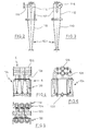
- the hydrocyclone 16.1 is shown in more detail in FIGS. 2 and 3. He points a lower conical section 110, with a cone angle of approximately 10 °. It is connected to an upper cylindrical portion 112 into which a dip tube 114 protrudes from above, which is about half the height of the cylindrical portion 112 extends downward. A feed pipe 116 is tangential connected to the cylindrical section 112 in the upper region.
- the hydrocyclone 16.1 is designed in such a way that particles, their specific, are also separated Weight is only slightly larger than that of water or sea water.
- FIGS. 4 to 6 A battery of hydrocyclones is shown in FIGS. 4 to 6.
- the rows are labeled 180 and 120, respectively. They are held in a frame 124 which, for example, on the deck of a Ship can be set up.
- the arrangement of the cyclones is extraordinary compact and easy to accommodate even in tight spaces.
- the line 52 is indicated, which comes from the filter device 50 Output line. It has a side connection 132 through which a tube 134 is sealingly guided and has a nozzle 136 at the upper free end and which has a nozzle-like constriction 138 outside the line 52. Below the narrowing 38 is provided a side connection piece 140 which with the Metering pump 106 is connected. The lower end or inlet 142 of the Tube 134 is connected to the booster pump 82 according to FIG. 1. about Microbicide is introduced or injected into the tube 134 in the nozzle 140 and with the help of the flow acceleration in the nozzle-like constriction 138 the water coming from the booster pump 142 is already intensively mixed.
- FIG 8 shows the mixer as consisting of two tube halves 144, 146, which are divided in the middle.
- segment-like Flow baffles 148 are arranged, each having a V-shaped flow cross-section form, the V-shaped cross section rotated at center distances is so that the flow is rotated about its longitudinal axis.
- the pressure drop in one such static mixer 92 is about 0.2 to 0.4 bar.
- hydrocyclones 16.1 to 16.6 have a wear-resistant, corrosion-resistant surface, e.g. provided with a ceramic coating can be, which reduces the frictional resistance and a resistance against abrasion and corrosion.
- a third control device for the supply of the microbicide regulates from the container 108 into the outlet line 52 in which the quantity measuring device 60, which measures the volume flowing in line 52, the Metering pump 106 promotes the microbicide in accordance with the measured volume.
Landscapes
- Engineering & Computer Science (AREA)
- Architecture (AREA)
- Organic Chemistry (AREA)
- Environmental & Geological Engineering (AREA)
- Water Supply & Treatment (AREA)
- Chemical & Material Sciences (AREA)
- Life Sciences & Earth Sciences (AREA)
- Hydrology & Water Resources (AREA)
- Mechanical Engineering (AREA)
- Civil Engineering (AREA)
- Structural Engineering (AREA)
- Physical Water Treatments (AREA)
- Treatment Of Water By Oxidation Or Reduction (AREA)
- Separation Of Suspended Particles By Flocculating Agents (AREA)
- Water Treatment By Sorption (AREA)
Abstract
Description
- Fig. 1
- zeigt schematisch eine Anlage nach der Erfindung.
- Fig. 2
- zeigt einen Hydrozyklon der Anlage nach Fig. 1 in Seitenansicht.
- Fig.
- 3 zeigt die Seitenansicht des Hydrozyklons nach Fig. 2 um 180° verdreht.
- Fig. 4
- zeigt die Seitenansicht einer Gruppe von Hydrozyklonen für die Anlage nach Fig. 1
- Fig. 5
- zeigt die Draufsicht auf die Gruppe nach Fig. 4.
- Fig. 6
- zeigt die Seitenansicht der Hydrozyklone nach Fig. 4.
- Fig. 7
- zeigt im Schnitt die Einspeisung des Mikrobizids in die Ausgangsleitung der Filtervorrichtung.
- Fig. 8
- zeigt eine schematische auseinandergezogene perspektivische Ansicht eines statischen Mischers der Anlage nach Fig. 1.
Claims (24)
- Anlage zur Entfernung und Deaktivierung von Organismen im Ballastwasser, mit den folgenden Merkmalen:eine erste Förderpumpe (10) zum Fördern des Ballastwassers,eine an die erste Förderpumpe (10) angeschlossene Vorrichtung zur Schwerkraftabscheidung gröberer Feststoffe und größerer Organismen und/oder eine rückspülbare Filtervorrichtung (50),eine nachgeschaltete Vorrichtung zur Deaktivierung von Mikrokeimen.
- Ablage nach Anspruch 1, dadurch gekennzeichnet, daß die Vorrichtung zur Schwerkraftabscheidung eine Anordnung (A) von parallel geschalteten zu- bzw. abschaltbaren Hydrozyklonen (16.1 bis 16.6) aufweist und eine Steuervorrichtung, die die Zahl der eingeschalteten Hydrozyklone (16.1 bis 16.6) nach Maßgabe der gemessenen Fördermenge der ersten Förderpumpe (10) steuert.
- Anlage nach Anspruch 1 und 2, dadurch gekennzeichnet, daß zur Schwerkraftabscheidung mindestens eine Zentrifuge vorgesehen ist.
- Anlage nach einem der Ansprüche 1 bis 3, dadurch gekennzeichnet, daß die erste Förderpumpe (10) eine Kreiselpumpe ist.
- Anlage nach einem der Ansprüche 2 bis 4, dadurch gekennzeichnet, daß der Unterlauf der Hydrozyklone (16.1 bis 16.6) mit einer zweiten Förderpumpe (32) verbunden, der eine erste Regelvorrichtung zugeordnet ist, die die Fördermenge zum Unterlauf mißt und in Abhängigkeit von der Anzahl der eingeschalteten Hydrozyklone (16.1 bis 16.6) einen vorgegebenen konstanten Mengenstrom fördert.
- Anlage nach einem der Ansprüche 2 bis 4, dadurch gekennzeichnet, daß mindestens bei einem Teil der Hydrozyklone dem Unterlauf jeweils eine Abförderpumpe zugeordnet ist.
- Anlage nach Anspruch 5 oder 6, dadurch gekennzeichnet, daß die zweite Förderpumpe (32) eine Verdrängerpumpe ist.
- Anlage nach Anspruch 5, dadurch gekennzeichnet, daß eine Alarmvorrichtung vorgesehen ist, die eine Alarmgabe bewirkt, wenn die Regelabweichung einen vorgegebenen Wert erreicht.
- Anlage nach einem der Ansprüche 1 bis 8, dadurch gekennzeichnet, daß in der Leitung (36) zur Filtervorrichtung (50) ein Regelventil (38) angeordnet ist, dem eine zweite Regelvorrichtung zugeordnet ist, die durch Regelung des Durchströmquerschnitts des Regelventils (38) einen vorgegebenen Druck in der aufströmseitigen Leitung (20) aufrechterhält.
- Anlage nach einem der Ansprüche 1 bis 9, dadurch gekennzeichnet, daß die Filtervorrichtung (50) so ausgebildet ist, daß bei Umschaltung auf Rückspülbetrieb ihr Einlauf mit der Ablaufseite einer Filterfläche verbunden ist, während die Einlaufseite der Filterfläche mit einer Rückspülpumpe (70) in einem Rückspülzweig (66) verbunden ist.
- Anlage nach Anspruch 10, dadurch gekennzeichnet, daß zwischen Ein- und Auslauf der Filtervorrichtung (50) ein Druckmesser (102) geschaltet ist und die Steuervorrichtung den Rückspülbetrieb in Gang setzt, wenn der Druck einen vorgegebenen Wert erreicht.
- Anlage nach einem der Ansprüche 1 bis 11, dadurch gekennzeichnet, daß eine an ein Reservoir (108) für Biozid angeschlossene Dosiervorrichtung mit der Ausgangsleitung (52) der Filtervorrichtung (50) verbunden ist.
- Anlage nach Anspruch 12, dadurch gekennzeichnet, daß zwischen dem Einleitungspunkt für das Biozid in der Ausgangsleitung (52) und einem aufströmseitigen Punkt der Ausgangsleitung (52) eine Druckerhöhungspumpe (82) parallel geschaltet ist und eine Dosierpumpe (106) das Biozid in die Ausgangsleitung der Druckerhöhungspumpe (82) eingibt.
- Anlage nach Anspruch 13, dadurch gekennzeichnet, daß die Druckerhöhungspumpe (82) mit dem Ende eines Einleitungsrohrs verbunden ist, das eine düsenförmige Verengung (138) abströmseitig des Anschlusses der Dosierpumpe (106) aufweist.
- Anlage nach Anspruch 14, dadurch gekennzeichnet, daß das Rohr (134) am Ende eine Düse (136) aufweist, die annähernd in der Mitte der Ausgangsleitung (52) mündet.
- Anlage nach einem der Ansprüche 12 bis 15, dadurch gekennzeichnet, daß eine dritte Regelvorrichtung vorgesehen ist, welche die Dosiermenge der Dosierpumpe (106) nach Maßgabe der Fördermenge in der Ausgangsleitung (52) regelt.
- Anlage nach einem der Ansprüche 12 bis 16, dadurch gekennzeichnet, daß abströmseitig des Einleitungspunktes des Biozids in der Ausgangsleitung (52) ein statischer Mischer (92) angeordnet ist.
- Anlage nach Anspruch 17, dadurch gekennzeichnet, daß der statische Mischer (92) einen geringen Druckverlust aufweist.
- Anlage nach einem der Ansprüche 1 bis 18, dadurch gekennzeichnet, daß ein absperrbarer Bypass (62) für die Filtervorrichtung (50) vorgesehen ist.
- Anlage nach einem der Ansprüche 2 bis 19, dadurch gekennzeichnet, daß ein absperrbarer Bypass (89) für die Hydrozyklone (16.1 bis 16.6) vorgesehen ist.
- Anlage nach einem der Ansprüche 1 bis 17, dadurch gekennzeichnet, daß die Hydrozyklone (16.1 bis 16.6) in Reihe in einem gemeinsamen Rahmen (124) angebracht sind und Oberlauf, Unterlauf und Zulaufleitung mit parallel angeordneten Rohren (126, 128, 130) verbunden sind.
- Anlage nach Anspruch 21, dadurch gekennzeichnet, daß zwei Reihen (118, 120) von parallel angeordneten Hydrozyklonen vorgesehen sind und die parallelen Rohre annähernd mittig zwischen den Reihen (118, 120) angeordnet sind.
- Anlage nach einem der Ansprüche 1 bis 22, dadurch gekennzeichnet, daß die Filtervorrichtung (50) eine Porengröße von 50µm bis 300µm aufweist.
- Anlage nach einem der Ansprüche 1 bis 23, dadurch gekennzeichnet, daß die Hydrozyklone (16.1 bis 16.6) eine verschleißfeste und korrosionsbeständige Oberfläche aufweisen.
Applications Claiming Priority (2)
| Application Number | Priority Date | Filing Date | Title |
|---|---|---|---|
| DE20302516U DE20302516U1 (de) | 2003-02-15 | 2003-02-15 | Anlage zur Entfernung und Deaktivierung von Organismen im Ballastwasser |
| DE20302516U | 2003-02-15 |
Publications (2)
| Publication Number | Publication Date |
|---|---|
| EP1447384A1 true EP1447384A1 (de) | 2004-08-18 |
| EP1447384B1 EP1447384B1 (de) | 2008-12-03 |
Family
ID=29762278
Family Applications (1)
| Application Number | Title | Priority Date | Filing Date |
|---|---|---|---|
| EP04000485A Expired - Lifetime EP1447384B1 (de) | 2003-02-15 | 2004-01-13 | Anlage zur Entfernung und Deaktivierung von Organismen im Ballastwasser |
Country Status (6)
| Country | Link |
|---|---|
| US (1) | US7198713B2 (de) |
| EP (1) | EP1447384B1 (de) |
| KR (1) | KR20040073970A (de) |
| AT (1) | ATE416149T1 (de) |
| DE (2) | DE20302516U1 (de) |
| DK (1) | DK1447384T3 (de) |
Cited By (6)
| Publication number | Priority date | Publication date | Assignee | Title |
|---|---|---|---|---|
| DE102006045558A1 (de) * | 2006-09-25 | 2008-04-03 | Rwo Gmbh | Wasseraufbereitungsanlage |
| US8702460B2 (en) | 2010-02-11 | 2014-04-22 | Allen Szydlowski | Method and system for a towed vessel suitable for transporting liquids |
| US8715756B2 (en) | 2005-10-21 | 2014-05-06 | Juan Carlos Szydlowski | Method and system for recovering and preparing glacial water |
| US10399642B2 (en) | 2009-10-15 | 2019-09-03 | World's Fresh Waters Pte. Ltd | Method and system for processing glacial water |
| US10435118B2 (en) | 2009-10-15 | 2019-10-08 | Allen Szydlowski | Method and system for a towed vessel suitable for transporting liquids |
| US11584483B2 (en) | 2010-02-11 | 2023-02-21 | Allen Szydlowski | System for a very large bag (VLB) for transporting liquids powered by solar arrays |
Families Citing this family (18)
| Publication number | Priority date | Publication date | Assignee | Title |
|---|---|---|---|---|
| US20080164217A1 (en) * | 2004-02-13 | 2008-07-10 | Kazuki Nishizawa | Method of Liquid Detoxification and Apparatus Therefor |
| JP2007537036A (ja) * | 2004-05-11 | 2007-12-20 | メタフィル エーエス | バラスト水システム |
| GB0411180D0 (en) * | 2004-05-19 | 2004-06-23 | Reederei Hesse Gmbh & Co Kg | Treatment of ballast water |
| EP1771255B1 (de) * | 2004-05-19 | 2008-10-08 | Reederei Hesse GmbH & Co. KG | Behandlung von ballastwasser |
| JP4699774B2 (ja) * | 2005-02-18 | 2011-06-15 | 株式会社片山化学工業研究所 | 船舶バラスト水の処理方法 |
| US9521858B2 (en) | 2005-10-21 | 2016-12-20 | Allen Szydlowski | Method and system for recovering and preparing glacial water |
| US9010261B2 (en) | 2010-02-11 | 2015-04-21 | Allen Szydlowski | Method and system for a towed vessel suitable for transporting liquids |
| EP2066589A4 (de) * | 2006-09-26 | 2012-12-12 | Alfawall Aktiebolag | System zur wasseraufbereitung |
| US8025795B2 (en) * | 2007-02-09 | 2011-09-27 | Maritime Solutions, Inc. | Ballast water treatment system |
| US20090211507A1 (en) * | 2008-02-25 | 2009-08-27 | Ian Fielding | System and method for the collection and disposal of ballast water, bilge water and waste water |
| US9017123B2 (en) | 2009-10-15 | 2015-04-28 | Allen Szydlowski | Method and system for a towed vessel suitable for transporting liquids |
| KR101647388B1 (ko) * | 2012-04-12 | 2016-08-10 | 대우조선해양 주식회사 | Fpso 열교환 시스템 |
| US9688551B2 (en) * | 2012-06-18 | 2017-06-27 | The United States Of America As Represented By The Secretary Of The Interior | Nozzle mixing apparatus and methods for treating water in ship ballast tanks |
| CN102874966B (zh) * | 2012-10-23 | 2014-10-22 | 九江精密测试技术研究所 | 一种船舶压载水处理系统 |
| WO2014073105A1 (ja) * | 2012-11-12 | 2014-05-15 | 三浦工業株式会社 | バラスト水処理装置 |
| US10370263B2 (en) | 2012-11-12 | 2019-08-06 | Miura Co., Ltd. | Ballast water treatment device |
| CN103752068B (zh) * | 2014-01-17 | 2015-06-17 | 云南大红山管道有限公司 | 一种反冲水系统和反冲水方法 |
| EP3666640A1 (de) * | 2018-12-14 | 2020-06-17 | ABB Schweiz AG | Wasserbehandlungsvorrichtung |
Citations (4)
| Publication number | Priority date | Publication date | Assignee | Title |
|---|---|---|---|---|
| US5807486A (en) * | 1994-11-01 | 1998-09-15 | Joseph B. Busch, Sr. et al. | Process for the treatment of hazardous waste water |
| WO2002044089A2 (en) * | 2000-11-28 | 2002-06-06 | Ecochlor, Inc. | Methods, apparatus, and compositions for controlling organisms in ballast water |
| US6464884B1 (en) * | 1999-08-26 | 2002-10-15 | The Regents Of The University Of California | Portable water treatment unit |
| US20030015481A1 (en) * | 2001-06-28 | 2003-01-23 | Eidem Ola Magne | Method and apparatus for treating/disinfecting ballast water in ships |
Family Cites Families (18)
| Publication number | Priority date | Publication date | Assignee | Title |
|---|---|---|---|---|
| US1181762A (en) * | 1914-09-09 | 1916-05-02 | Charles F Hathaway | Filter. |
| US2228017A (en) * | 1936-02-03 | 1941-01-07 | American Centrifugal Corp | Sewage disposal |
| US3577341A (en) * | 1968-10-18 | 1971-05-04 | Pennwalt Corp | Water treatment |
| US3677405A (en) * | 1970-09-25 | 1972-07-18 | Pennwalt Corp | Liquid and sludge treatment |
| DE3148838A1 (de) * | 1981-12-10 | 1983-06-23 | Bayer Ag, 5090 Leverkusen | Verwendung fluessiger, kalthaertender polyurethanbildender komponenten fuer korrosionshemmende, verschleissschuetzende beschichtungen von metall- und kunststoff-flaechen und -formkoerpern sowie von gestein und beton |
| US4680109A (en) * | 1985-05-17 | 1987-07-14 | Ebara Corporation | Membrane separator |
| JP2575975B2 (ja) * | 1991-09-17 | 1997-01-29 | 株式会社東芝 | ろ過装置 |
| US5158677A (en) * | 1991-09-20 | 1992-10-27 | Hewitt Robert M | Machine coolant reclamation apparatus |
| DE4312731C2 (de) * | 1993-04-20 | 1995-04-20 | Taprogge Gmbh | Rückspülbares Filter |
| GB2312892A (en) | 1996-05-10 | 1997-11-12 | Douglas Bolton | Multi-stage treatment of contaminated water |
| US5932112A (en) * | 1996-11-27 | 1999-08-03 | Browning Transport Management, Inc. | Method and apparatus for killing microorganisms in ship ballast water |
| US6458268B1 (en) * | 1999-06-22 | 2002-10-01 | Ecolab Inc. | Industrial waste water treatment cleaning apparatus |
| DE19937989B4 (de) | 1999-08-11 | 2004-05-13 | Fraunhofer-Gesellschaft zur Förderung der angewandten Forschung e.V. | Mobile Entsorgungsanlage |
| IL133084A (en) | 1999-11-22 | 2003-12-10 | B H Technologies 1998 Ltd | Method for removal of solid deposits from electrode surfaces in water disinfecting system using electrolytic cells and a device for use thereof |
| US6346197B1 (en) * | 2000-01-28 | 2002-02-12 | Mckay Creek Technologies Ltd. | Water and wastewater treatment system and process for contaminant removal |
| DE10119119B4 (de) | 2001-04-19 | 2009-11-26 | Mahle International Gmbh | Verfahren zur Aufbereitung von Brauchwasser |
| US6775120B2 (en) * | 2001-07-23 | 2004-08-10 | Adc Telecommunications, Inc. | Power distribution bus with protection and alarming |
| US6565744B2 (en) * | 2001-09-07 | 2003-05-20 | Mikhail Levitin | Waste water cleaning system |
-
2003
- 2003-02-15 DE DE20302516U patent/DE20302516U1/de not_active Expired - Lifetime
-
2004
- 2004-01-13 EP EP04000485A patent/EP1447384B1/de not_active Expired - Lifetime
- 2004-01-13 DK DK04000485T patent/DK1447384T3/da active
- 2004-01-13 DE DE502004008562T patent/DE502004008562D1/de not_active Expired - Lifetime
- 2004-01-13 AT AT04000485T patent/ATE416149T1/de not_active IP Right Cessation
- 2004-01-30 KR KR1020040005912A patent/KR20040073970A/ko not_active Abandoned
- 2004-02-03 US US10/771,032 patent/US7198713B2/en not_active Expired - Fee Related
Patent Citations (4)
| Publication number | Priority date | Publication date | Assignee | Title |
|---|---|---|---|---|
| US5807486A (en) * | 1994-11-01 | 1998-09-15 | Joseph B. Busch, Sr. et al. | Process for the treatment of hazardous waste water |
| US6464884B1 (en) * | 1999-08-26 | 2002-10-15 | The Regents Of The University Of California | Portable water treatment unit |
| WO2002044089A2 (en) * | 2000-11-28 | 2002-06-06 | Ecochlor, Inc. | Methods, apparatus, and compositions for controlling organisms in ballast water |
| US20030015481A1 (en) * | 2001-06-28 | 2003-01-23 | Eidem Ola Magne | Method and apparatus for treating/disinfecting ballast water in ships |
Non-Patent Citations (2)
| Title |
|---|
| "REGAL PRINCESS BECOMES FIRST CRUISE SHIP TO RETROFIT BALLAST WATER TREATMENT PLANT", MARINE ENGINEERS REVIEW, INSTITUTE OF MARINE ENGINEERS. LONDON, GB, July 2000 (2000-07-01), pages 13 - 14, XP000965818, ISSN: 0047-5955 * |
| SUTHERLAND T F ET AL: "Effect of a ballast water treatment system on survivorship of natural populations of marine plankton", MARINE ECOLOGY PROGRESS SERIES, no. 210, 26 January 2001 (2001-01-26), pages 139 - 148, XP002277680, ISSN: 0171-8630 * |
Cited By (7)
| Publication number | Priority date | Publication date | Assignee | Title |
|---|---|---|---|---|
| US8715756B2 (en) | 2005-10-21 | 2014-05-06 | Juan Carlos Szydlowski | Method and system for recovering and preparing glacial water |
| DE102006045558A1 (de) * | 2006-09-25 | 2008-04-03 | Rwo Gmbh | Wasseraufbereitungsanlage |
| US10399642B2 (en) | 2009-10-15 | 2019-09-03 | World's Fresh Waters Pte. Ltd | Method and system for processing glacial water |
| US10435118B2 (en) | 2009-10-15 | 2019-10-08 | Allen Szydlowski | Method and system for a towed vessel suitable for transporting liquids |
| US10953956B2 (en) | 2009-10-15 | 2021-03-23 | Allen Szydlowski | Method and system for a towed vessel suitable for transporting liquids |
| US8702460B2 (en) | 2010-02-11 | 2014-04-22 | Allen Szydlowski | Method and system for a towed vessel suitable for transporting liquids |
| US11584483B2 (en) | 2010-02-11 | 2023-02-21 | Allen Szydlowski | System for a very large bag (VLB) for transporting liquids powered by solar arrays |
Also Published As
| Publication number | Publication date |
|---|---|
| DE20302516U1 (de) | 2003-12-11 |
| DE502004008562D1 (de) | 2009-01-15 |
| DK1447384T3 (da) | 2009-03-23 |
| KR20040073970A (ko) | 2004-08-21 |
| ATE416149T1 (de) | 2008-12-15 |
| EP1447384B1 (de) | 2008-12-03 |
| US7198713B2 (en) | 2007-04-03 |
| US20040159599A1 (en) | 2004-08-19 |
Similar Documents
| Publication | Publication Date | Title |
|---|---|---|
| EP1447384B1 (de) | Anlage zur Entfernung und Deaktivierung von Organismen im Ballastwasser | |
| DE2457315C3 (de) | Einrichtung zum Behandeln von ölverschmutztem Ballastwasser auf Schiffen | |
| EP0306030B1 (de) | Einrichtung zum kontinuierlichen Erzeugen einer flüssigen Mischung von Fest- und Flüssigstoffen | |
| DE102006045558A1 (de) | Wasseraufbereitungsanlage | |
| DE102015112092B4 (de) | Öl/Wasser-Trennvorrichtung mit Druckluftbeaufschlagung | |
| DE1939648A1 (de) | Verfahren und Anlage zur Abwasserbehandlung | |
| DE4335996C2 (de) | Verfahren und Vorrichtung zum Reinigen von schwach verunreinigtem Wasser | |
| EP1108822A1 (de) | Abwasserhebeanlage | |
| WO2019185908A1 (de) | Vorrichtung und verfahren zum aufbereiten von trinkwasser | |
| DE68918864T2 (de) | Gerät zum Einspritzen eines Zusatzstoffes in eine Flüssigkeit. | |
| DE102004038125A1 (de) | Trennapparat für Suspensionen | |
| DE69913992T2 (de) | Doppelkonus zur erzeugung einer druckdifferenz | |
| EP0588778A1 (de) | Anlage zur Reinigung von Waschwasser, insbesondere bei Fahrzeugwaschanlagen | |
| DE3120891A1 (de) | Verfahren zur entfernung bzw. teilentfernung von in einem ein gefaelle aufweisenden fliessgewaesser enthaltenen stoerenden inhaltsstoffen und vorrichtung zur durchfuehrung des verfahrens | |
| CH637602A5 (en) | Process and equipment for clarifying effluents | |
| EP2326551A2 (de) | Vorrichtung zur abwasseraufbereitung | |
| DE3638023C2 (de) | Anlage zur Behandlung industriellen Abwassers | |
| DE2537312C3 (de) | Speisebehälter für eine Pumpanlage | |
| CH635757A5 (en) | Apparatus for metering a liquid additive into a bulk liquid | |
| DE3490415C2 (de) | Vorrichtung zum Neutralisieren von saurem Wasser | |
| DE10001610C2 (de) | Vorrichtung zur Aufbereitung von Abwasser | |
| DE2263412A1 (de) | Vorrichtung zum aufbereiten von fluessigkeiten, insb. des trinkwassers auf schiffen | |
| DE4441970C2 (de) | Entsorgungsvorrichtung zur Abscheidung von Öl aus Schmutzwasser mit Restölgehaltskontrolle | |
| DE2263752C3 (de) | Vorrichtung und Verfahren zum Stabilisieren von Abwasserschlamm oder ähnlichem Abfallmaterial | |
| DE8109529U1 (de) | Vorrichtung zur Herstellung von Dialysierflüssigkeit zur Verwendung in Hämodialysegeräten |
Legal Events
| Date | Code | Title | Description |
|---|---|---|---|
| PUAI | Public reference made under article 153(3) epc to a published international application that has entered the european phase |
Free format text: ORIGINAL CODE: 0009012 |
|
| AK | Designated contracting states |
Kind code of ref document: A1 Designated state(s): AT BE BG CH CY CZ DE DK EE ES FI FR GB GR HU IE IT LI LU MC NL PT RO SE SI SK TR |
|
| AX | Request for extension of the european patent |
Extension state: AL LT LV MK |
|
| 17P | Request for examination filed |
Effective date: 20041029 |
|
| AKX | Designation fees paid |
Designated state(s): AT BE BG CH CY CZ DE DK EE ES FI FR GB GR HU IE IT LI LU MC NL PT RO SE SI SK TR |
|
| GRAP | Despatch of communication of intention to grant a patent |
Free format text: ORIGINAL CODE: EPIDOSNIGR1 |
|
| GRAS | Grant fee paid |
Free format text: ORIGINAL CODE: EPIDOSNIGR3 |
|
| GRAA | (expected) grant |
Free format text: ORIGINAL CODE: 0009210 |
|
| AK | Designated contracting states |
Kind code of ref document: B1 Designated state(s): AT BE BG CH CY CZ DE DK EE ES FI FR GB GR HU IE IT LI LU MC NL PT RO SE SI SK TR |
|
| REG | Reference to a national code |
Ref country code: GB Ref legal event code: FG4D Free format text: NOT ENGLISH |
|
| REG | Reference to a national code |
Ref country code: CH Ref legal event code: EP |
|
| REG | Reference to a national code |
Ref country code: IE Ref legal event code: FG4D Free format text: LANGUAGE OF EP DOCUMENT: GERMAN |
|
| REF | Corresponds to: |
Ref document number: 502004008562 Country of ref document: DE Date of ref document: 20090115 Kind code of ref document: P |
|
| REG | Reference to a national code |
Ref country code: GR Ref legal event code: EP Ref document number: 20090400234 Country of ref document: GR |
|
| REG | Reference to a national code |
Ref country code: SE Ref legal event code: TRGR |
|
| REG | Reference to a national code |
Ref country code: DK Ref legal event code: T3 |
|
| PG25 | Lapsed in a contracting state [announced via postgrant information from national office to epo] |
Ref country code: ES Free format text: LAPSE BECAUSE OF FAILURE TO SUBMIT A TRANSLATION OF THE DESCRIPTION OR TO PAY THE FEE WITHIN THE PRESCRIBED TIME-LIMIT Effective date: 20090314 |
|
| PG25 | Lapsed in a contracting state [announced via postgrant information from national office to epo] |
Ref country code: SI Free format text: LAPSE BECAUSE OF FAILURE TO SUBMIT A TRANSLATION OF THE DESCRIPTION OR TO PAY THE FEE WITHIN THE PRESCRIBED TIME-LIMIT Effective date: 20081203 |
|
| REG | Reference to a national code |
Ref country code: IE Ref legal event code: FD4D |
|
| PG25 | Lapsed in a contracting state [announced via postgrant information from national office to epo] |
Ref country code: EE Free format text: LAPSE BECAUSE OF FAILURE TO SUBMIT A TRANSLATION OF THE DESCRIPTION OR TO PAY THE FEE WITHIN THE PRESCRIBED TIME-LIMIT Effective date: 20081203 Ref country code: IE Free format text: LAPSE BECAUSE OF FAILURE TO SUBMIT A TRANSLATION OF THE DESCRIPTION OR TO PAY THE FEE WITHIN THE PRESCRIBED TIME-LIMIT Effective date: 20081203 Ref country code: BG Free format text: LAPSE BECAUSE OF FAILURE TO SUBMIT A TRANSLATION OF THE DESCRIPTION OR TO PAY THE FEE WITHIN THE PRESCRIBED TIME-LIMIT Effective date: 20090303 Ref country code: RO Free format text: LAPSE BECAUSE OF FAILURE TO SUBMIT A TRANSLATION OF THE DESCRIPTION OR TO PAY THE FEE WITHIN THE PRESCRIBED TIME-LIMIT Effective date: 20081203 |
|
| PG25 | Lapsed in a contracting state [announced via postgrant information from national office to epo] |
Ref country code: CZ Free format text: LAPSE BECAUSE OF FAILURE TO SUBMIT A TRANSLATION OF THE DESCRIPTION OR TO PAY THE FEE WITHIN THE PRESCRIBED TIME-LIMIT Effective date: 20081203 Ref country code: PT Free format text: LAPSE BECAUSE OF FAILURE TO SUBMIT A TRANSLATION OF THE DESCRIPTION OR TO PAY THE FEE WITHIN THE PRESCRIBED TIME-LIMIT Effective date: 20090504 Ref country code: MC Free format text: LAPSE BECAUSE OF NON-PAYMENT OF DUE FEES Effective date: 20090131 |
|
| REG | Reference to a national code |
Ref country code: CH Ref legal event code: PL |
|
| PG25 | Lapsed in a contracting state [announced via postgrant information from national office to epo] |
Ref country code: SK Free format text: LAPSE BECAUSE OF FAILURE TO SUBMIT A TRANSLATION OF THE DESCRIPTION OR TO PAY THE FEE WITHIN THE PRESCRIBED TIME-LIMIT Effective date: 20081203 |
|
| PLBE | No opposition filed within time limit |
Free format text: ORIGINAL CODE: 0009261 |
|
| STAA | Information on the status of an ep patent application or granted ep patent |
Free format text: STATUS: NO OPPOSITION FILED WITHIN TIME LIMIT |
|
| PG25 | Lapsed in a contracting state [announced via postgrant information from national office to epo] |
Ref country code: LI Free format text: LAPSE BECAUSE OF NON-PAYMENT OF DUE FEES Effective date: 20090131 Ref country code: CH Free format text: LAPSE BECAUSE OF NON-PAYMENT OF DUE FEES Effective date: 20090131 |
|
| 26N | No opposition filed |
Effective date: 20090904 |
|
| PG25 | Lapsed in a contracting state [announced via postgrant information from national office to epo] |
Ref country code: BE Free format text: LAPSE BECAUSE OF NON-PAYMENT OF DUE FEES Effective date: 20090131 |
|
| PG25 | Lapsed in a contracting state [announced via postgrant information from national office to epo] |
Ref country code: AT Free format text: LAPSE BECAUSE OF NON-PAYMENT OF DUE FEES Effective date: 20090113 |
|
| PG25 | Lapsed in a contracting state [announced via postgrant information from national office to epo] |
Ref country code: IT Free format text: LAPSE BECAUSE OF NON-PAYMENT OF DUE FEES Effective date: 20090113 |
|
| PG25 | Lapsed in a contracting state [announced via postgrant information from national office to epo] |
Ref country code: LU Free format text: LAPSE BECAUSE OF NON-PAYMENT OF DUE FEES Effective date: 20090113 |
|
| PGFP | Annual fee paid to national office [announced via postgrant information from national office to epo] |
Ref country code: DK Payment date: 20110125 Year of fee payment: 8 |
|
| PGFP | Annual fee paid to national office [announced via postgrant information from national office to epo] |
Ref country code: NL Payment date: 20110119 Year of fee payment: 8 Ref country code: FI Payment date: 20110120 Year of fee payment: 8 Ref country code: FR Payment date: 20110201 Year of fee payment: 8 Ref country code: DE Payment date: 20110309 Year of fee payment: 8 Ref country code: SE Payment date: 20110121 Year of fee payment: 8 |
|
| PG25 | Lapsed in a contracting state [announced via postgrant information from national office to epo] |
Ref country code: HU Free format text: LAPSE BECAUSE OF FAILURE TO SUBMIT A TRANSLATION OF THE DESCRIPTION OR TO PAY THE FEE WITHIN THE PRESCRIBED TIME-LIMIT Effective date: 20090604 |
|
| PGFP | Annual fee paid to national office [announced via postgrant information from national office to epo] |
Ref country code: GR Payment date: 20110125 Year of fee payment: 8 |
|
| PGFP | Annual fee paid to national office [announced via postgrant information from national office to epo] |
Ref country code: GB Payment date: 20110121 Year of fee payment: 8 Ref country code: IT Payment date: 20110126 Year of fee payment: 8 |
|
| PGRI | Patent reinstated in contracting state [announced from national office to epo] |
Ref country code: IT Effective date: 20110616 |
|
| PG25 | Lapsed in a contracting state [announced via postgrant information from national office to epo] |
Ref country code: TR Free format text: LAPSE BECAUSE OF FAILURE TO SUBMIT A TRANSLATION OF THE DESCRIPTION OR TO PAY THE FEE WITHIN THE PRESCRIBED TIME-LIMIT Effective date: 20081203 |
|
| PG25 | Lapsed in a contracting state [announced via postgrant information from national office to epo] |
Ref country code: CY Free format text: LAPSE BECAUSE OF FAILURE TO SUBMIT A TRANSLATION OF THE DESCRIPTION OR TO PAY THE FEE WITHIN THE PRESCRIBED TIME-LIMIT Effective date: 20081203 |
|
| REG | Reference to a national code |
Ref country code: NL Ref legal event code: V1 Effective date: 20120801 |
|
| REG | Reference to a national code |
Ref country code: SE Ref legal event code: EUG |
|
| REG | Reference to a national code |
Ref country code: DK Ref legal event code: EBP |
|
| REG | Reference to a national code |
Ref country code: GR Ref legal event code: ML Ref document number: 20090400234 Country of ref document: GR Effective date: 20120802 |
|
| GBPC | Gb: european patent ceased through non-payment of renewal fee |
Effective date: 20120113 |
|
| REG | Reference to a national code |
Ref country code: FR Ref legal event code: ST Effective date: 20120928 |
|
| PG25 | Lapsed in a contracting state [announced via postgrant information from national office to epo] |
Ref country code: GB Free format text: LAPSE BECAUSE OF NON-PAYMENT OF DUE FEES Effective date: 20120113 Ref country code: FI Free format text: LAPSE BECAUSE OF NON-PAYMENT OF DUE FEES Effective date: 20120113 Ref country code: DE Free format text: LAPSE BECAUSE OF NON-PAYMENT OF DUE FEES Effective date: 20120801 Ref country code: SE Free format text: LAPSE BECAUSE OF NON-PAYMENT OF DUE FEES Effective date: 20120114 |
|
| REG | Reference to a national code |
Ref country code: DE Ref legal event code: R119 Ref document number: 502004008562 Country of ref document: DE Effective date: 20120801 |
|
| PG25 | Lapsed in a contracting state [announced via postgrant information from national office to epo] |
Ref country code: IT Free format text: LAPSE BECAUSE OF NON-PAYMENT OF DUE FEES Effective date: 20120113 Ref country code: GR Free format text: LAPSE BECAUSE OF NON-PAYMENT OF DUE FEES Effective date: 20120802 |
|
| PG25 | Lapsed in a contracting state [announced via postgrant information from national office to epo] |
Ref country code: FR Free format text: LAPSE BECAUSE OF NON-PAYMENT OF DUE FEES Effective date: 20120131 |
|
| PG25 | Lapsed in a contracting state [announced via postgrant information from national office to epo] |
Ref country code: DK Free format text: LAPSE BECAUSE OF NON-PAYMENT OF DUE FEES Effective date: 20120131 Ref country code: NL Free format text: LAPSE BECAUSE OF NON-PAYMENT OF DUE FEES Effective date: 20120801 |