EP1447486B1 - Ablauf - Google Patents
Ablauf Download PDFInfo
- Publication number
- EP1447486B1 EP1447486B1 EP04000909A EP04000909A EP1447486B1 EP 1447486 B1 EP1447486 B1 EP 1447486B1 EP 04000909 A EP04000909 A EP 04000909A EP 04000909 A EP04000909 A EP 04000909A EP 1447486 B1 EP1447486 B1 EP 1447486B1
- Authority
- EP
- European Patent Office
- Prior art keywords
- drain
- opening
- outflow opening
- siphon
- relative
- Prior art date
- Legal status (The legal status is an assumption and is not a legal conclusion. Google has not performed a legal analysis and makes no representation as to the accuracy of the status listed.)
- Expired - Lifetime
Links
- 229920003023 plastic Polymers 0.000 claims abstract description 3
- 239000004033 plastic Substances 0.000 claims abstract description 3
- DNJIEGIFACGWOD-UHFFFAOYSA-N ethanethiol Chemical compound CCS DNJIEGIFACGWOD-UHFFFAOYSA-N 0.000 claims 1
- 230000000717 retained effect Effects 0.000 claims 1
- 238000000034 method Methods 0.000 description 5
- 230000007246 mechanism Effects 0.000 description 3
- 238000007789 sealing Methods 0.000 description 3
- 150000001875 compounds Chemical class 0.000 description 2
- 239000012530 fluid Substances 0.000 description 2
- 230000004888 barrier function Effects 0.000 description 1
- 238000010276 construction Methods 0.000 description 1
- 238000006073 displacement reaction Methods 0.000 description 1
- 238000009434 installation Methods 0.000 description 1
- 239000000463 material Substances 0.000 description 1
- 239000002184 metal Substances 0.000 description 1
Images
Classifications
-
- E—FIXED CONSTRUCTIONS
- E03—WATER SUPPLY; SEWERAGE
- E03C—DOMESTIC PLUMBING INSTALLATIONS FOR FRESH WATER OR WASTE WATER; SINKS
- E03C1/00—Domestic plumbing installations for fresh water or waste water; Sinks
- E03C1/12—Plumbing installations for waste water; Basins or fountains connected thereto; Sinks
- E03C1/28—Odour seals
- E03C1/29—Odour seals having housing containing dividing wall, e.g. tubular
Definitions
- the present invention relates to a drain, in particular for connecting sink, with an inlet and an outlet, between which a siphon-like deflection is provided as an odor trap, wherein the position of the inlet is adjustable in height relative to the position of the outlet.
- the housing consists of two mutually rotatable halves, one of which carries the inlet nozzle and the other the drain neck.
- the sockets run parallel to the axis of rotation, wherein at least one of the neck is arranged eccentrically to the axis of rotation.
- the present invention has for its object to provide a process, in particular for the connection of washbasins, which avoids the disadvantages mentioned above, is designed to save space and allows easy to install connection of drain pipes.
- the inlet and / or the outlet is arranged on a disc mounted on a housing part, wherein a central axis of the disc is arranged offset to a central axis of the housing part. It is thus possible to realize the height adjustment instead of by rotation of an entire housing part via a rotation of the disc. Even then, a height adjustment of the inlet relative to the outlet can be realized. Furthermore, several height adjustment devices can be combined with each other. In particular, it is advantageous if two eccentric adjusting devices are provided, since then the laterally occurring offset can be largely compensated.
- the process according to the invention can be made compact, since a height offset no longer has to be compensated by an obliquely running pipe. In addition, the connections are less stressed with the drainpipes, since an inclination can be avoided.
- a plurality of housing parts are provided for the height adjustment, which are rotatable relative to each other and / or displaced. This allows a height adjustment in a simple manner during assembly on the construction site, in particular the components to be connected in the adjustable height range can be pre-fixed beforehand.
- the housing part with the outlet via mounting means on a wall can be mounted.
- the drain is formed substantially cup-shaped and inlet and outlet formed by arranged on opposite sides of the pot nozzle.
- the siphon-like deflection can be realized in a relatively small space, wherein the axial extent of the pot in the direction of the interior space can be kept relatively small.
- the height adjustment of the sequence has at least two nested cup-shaped housing parts, wherein the inlet and / or the outlet is arranged eccentrically to a central axis of the cup-shaped housing parts or are.
- the housing parts can then be rotated relative to each other, so that due to the eccentric arrangement, a height offset of the inlet to the outlet.
- a ball joint may be provided that connects inlet or outlet to a housing part. Then, a connected pipe can also be arranged obliquely to the drain.
- the siphon-like deflection integrally formed with a housing part wall elements, which are closed with a lid. This makes the process easy to produce.
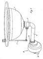
- a drain 10 is mounted below a washbasin 1 and connectable to an outlet 12 with a pipe emerging from a wall.
- the drain 10 also has an inlet, which is connected via an outlet pipe 4 with an outlet 2 of the washbasin 1.
- the drain pipe 4 is connected via a union nut 13 with the drain 10.
- a closure mechanism 3 is still shown schematically.
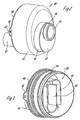
- the inlet 11 and the outlet 12 are arranged on opposite sides of the cup-shaped drain 10.
- the inlet 11 is formed by a nozzle with external thread 14 for the union nut 13 with a sealing ring, which is integrally formed on a disc 15.
- the disc 15 is sealed against an annular receptacle 16, which in turn is formed integrally with a cup-shaped housing part 17.
- the housing part 17 is sealed to another cup-shaped housing part 18 is connected to the flanges 19 are formed with an opening 25 so that the housing part 18 is fixed directly to a wall or a wall mounted frame.
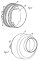
- a siphon-like deflection 20 is disposed within the housing part 18.
- the siphon-like deflection 20 comprises parallel to a central axis of the drain 10 extending wall elements 21 and 22, which are each U-shaped. Adjacent to the wall element 22, a connection to the outlet 12 is provided in the bottom region of the "U".
- the wall element 21 has the shape of an inverted "U” and surrounds the wall element 22 with its downwardly directed legs.
- the siphon-like deflection 20 is closed by a flat cover 23 and is thus integrated into the housing part 18.
- the housing part 17 can be rotated relative to the wall-mounted housing part 18, so that the annular receptacle 16 is adjusted by the eccentric arrangement relative to a central axis of the housing part 17 in height.
- the disc 15 can be sealed in the receptacle 16 rotate, the inlet 11 also eccentric to a central axis the disc 15 is arranged (Fig. 2).
- the inlet 11 can be arranged in different positions of the receptacle 16.
- the sealing of the disc 15 can be achieved by an annular projection, are provided on the grooves for sealing rings, which then bear against the receptacle 16 inside.
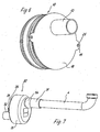
- Fig. 6 the process 10 is shown on the back.
- the outlet 12 is formed as a nozzle and integrally connected to the housing part 18.
- two eccentric devices are provided to make a height adjustment of the inlet 11 relative to the outlet 12 can. It is also possible to arrange only one eccentric device or more than two eccentric devices on the drain 10.
- a drain 30 is connected to a drain pipe 4.
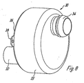
- the drain pipe 4 is mounted on an inlet 31 of the drain 30, which is connected via a ball joint 34 with a housing part 35.
- a ball joint 34 formed as a neck inlet 31 can be pivoted from a position parallel to a central axis of the cup-shaped drain 30 so that in an inclined drain pipe 4, the burden of the compounds is kept low.
- the housing part 35 is connected to a further cup-shaped housing part 36, which is mounted on flanges 38 on a wall.
- the housing parts 35 and 36 may otherwise be formed as in the first embodiment and have a corresponding siphon-like deflection 20 in the interior.
- all housing parts are made of plastic, although other suitable materials, such as metal can be used.
Landscapes
- Engineering & Computer Science (AREA)
- Water Supply & Treatment (AREA)
- Health & Medical Sciences (AREA)
- Life Sciences & Earth Sciences (AREA)
- Hydrology & Water Resources (AREA)
- Public Health (AREA)
- Environmental & Geological Engineering (AREA)
- Sink And Installation For Waste Water (AREA)
- Treating Waste Gases (AREA)
- Sanitary Device For Flush Toilet (AREA)
- Iron Core Of Rotating Electric Machines (AREA)
- Valve Device For Special Equipments (AREA)
- Sorption Type Refrigeration Machines (AREA)
Description
- Die vorliegende Erfindung betrifft einen Ablauf, insbesondere zum Anschluss von Waschbecken, mit einem Einlass und einem Auslass, zwischen denen eine siphonartige Umlenkung als Geruchsverschluss vorgesehen ist, wobei die Position des Einlasses relativ zu der Position des Auslasses höhenverstellbar ist.
- Es gibt Abläufe, die unterhalb eines Waschbeckens einen Siphon aufweisen und dann ausgehend von dem Siphon in ein Ablaufrohr münden, das in einer Gebäudewand fixiert ist. Die Anordnung des Siphons unterhalb des Waschbeckens ist nachteilig, weil dadurch Stauraum verloren geht, der beispielsweise durch ein Regal genutzt werden könnte. Zudem ist der Siphon optisch nicht besonders ansprechend und wird meist durch eine Verkleidung überdeckt. Ferner besteht der Nachteil, dass zwischen dem sich aus der Wand erstreckenden Ablaufrohr und dem Siphon keinerlei Höhenverstellung vorgesehen ist, so dass bei einem gewissen Versatz das Ablaufrohr leicht gebogen ist, was zu Installationsproblemen führen kann und auch die Lebensdauer der Verbindungen vermindern kann.
- Aus der
DE-C-842 479 ist ein Geruchverschluss für Ausgüsse bekannt, dessen Gehäuse aus zwei gegeneinander verdrehbaren Hälften besteht, von denen die eine den Zulaufstutzen und die andere den Ablaufstutzen trägt. Die Stutzen verlaufen parallel zur Verdrehungsachse, wobei zumindest einer der Stutzen exzentrisch zur Verdrehungsachse angeordnet ist. - Der vorliegenden Erfindung liegt die Aufgabe zugrunde, einen Ablauf, insbesondere zum Anschluss von Waschbecken, zu schaffen, der die oben genannten Nachteile vermeidet, raumsparend ausgebildet ist und einen einfach zu montierenden Anschluss von Ablaufrohren ermöglicht.
- Diese Aufgabe wird durch einen Ablauf mit den Merkmalen des Anspruchs 1 gelöst.
- Erfindungsgemäß ist der Einlass und/oder der Auslass an einer an einem Gehäuseteil gelagerten Scheibe angeordnet, wobei eine Mittelachse der Scheibe versetzt zu einer Mittelachse des Gehäuseteils angeordnet ist. Es ist somit möglich, die Höhenverstellung statt durch Drehung eines gesamten Gehäuseteiles über eine Drehung der Scheibe zu realisieren. Denn auch dann lässt sich eine Höhenverstellung des Einlasses relativ zu dem Auslass realisieren. Ferner können dabei mehrere Höhenverstelleinrichtungen miteinander kombiniert werden. Insbesondere ist es von Vorteil, wenn zwei exzentrische Verstelleinrichtungen vorgesehen sind, da dann der seitlich auftretende Versatz weitgehend kompensiert werden kann. Der erfindungsgemäße Ablauf lässt dabei kompakt ausführen, da ein Höhenversatz nicht mehr über ein schräg laufendes Rohr ausgeglichen werden muss. Zudem werden die Verbindungen mit den Ablaufrohren weniger stark beansprucht, da eine Schrägstellung vermieden werden kann.
- Gemäß einer bevorzugten Ausführungsform der Erfindung sind für die Höhenverstellung mehrere Gehäuseteile vorgesehen, die relativ zueinander drehbar und/oder verschiebbar sind. Dadurch kann eine Höhenverstellung auf einfache Weise bei der Montage auf der Baustelle erfolgen, insbesondere können die anzuschließenden Bauelemente in dem verstellbaren Höhenbereich vorher schon vorfixiert sein.
- Für eine kompakte Bauweise ist das Gehäuseteil mit dem Auslass über Befestigungsmittel an einer Wand montierbar. Dadurch entfällt die Notwendigkeit, den Ablauf mit der siphonartigen Umlenkung unmittelbar unter einem Ablaufrohr, beispielsweise unter einem Waschbecken, anzuordnen, so dass dieser Raum anderweitig genutzt werden kann. Vorzugsweise ist der Ablauf im wesentlichen topfförmig ausgebildet und Einlass und Auslass durch an gegenüberliegenden Seiten des Topfes angeordnete Stutzen gebildet. Dadurch kann die siphonartige Umlenkung auf relativ kleinem Bauraum realisiert werden, wobei die axiale Erstreckung des Topfes in Richtung des Rauminneren vergleichsweise klein gehalten werden kann.
- Für eine einfache Gestaltung der Höhenverstellbarkeit weist der Ablauf mindestens zwei ineinander gesteckte topfförmige Gehäuseteile auf, wobei der Einlass und/oder der Auslass exzentrisch zu einer Mittelachse der topfförmigen Gehäuseteile angeordnet ist bzw. sind. Für eine Höhenverstellung können die Gehäuseteile dann relativ zueinander gedreht werden, so dass aufgrund der exzentrischen Anordnung ein Höhenversatz des Einlasses zu dem Auslass erfolgt.
- Um mögliche Schrägstellungen am Einlass und/oder am Auslass besser handhaben zu können, kann ein Kugelgelenk vorgesehen sein, dass Einlass oder Auslass mit einem Gehäuseteil verbindet. Dann kann ein angeschlossenes Rohr auch schräg zu dem Ablauf angeordnet sein.
- Für eine besonders kompakte Bauweise weist die siphonartige Umlenkung integral mit einem Gehäuseteil ausgebildete Wandelemente auf, die mit einem Deckel verschlossen sind. Dadurch lässt sich der Ablauf auch einfach herstellen.
- Die Erfindung wird nachfolgend anhand von drei Ausführungsbeispielen mit Bezug auf die beigefügten Zeichnungen näher erläutert. Es zeigen:
- Fig. 1
- eine perspektivische Ansicht eines ersten Ausführungsbeispieles eines erfindungsgemäßen Ablaufes im montierten Zustand;
- Fig. 2
- eine vergrößerte perspektivische Ansicht des Ablaufs der Fig. 1;
- Fig. 3
- eine perspektivische Ansicht des Ablaufs der Fig. 1 mit einem abgenommenem Gehäuseteil;
- Fig. 4
- eine perspektivische Ansicht des Ablaufs der Fig. 1 mit abgenommenem Gehäuseteil;
- Fig. 5
- eine perspektivische Ansicht des Ablaufs der Fig. 1;
- Fig. 6
- eine perspektivische Rückansicht des Ablaufs der Fig. 1;
- Fig. 7
- eine perspektivische Ansicht eines Ablaufs gemäß einem zweiten Ausführungsbeispiel im montierten Zustand; und
- Fig. 8
- eine vergrößerte perspektivische Ansicht des Ablaufs der Fig. 7.
- Ein Ablauf 10 ist unterhalb eines Waschbeckens 1 montiert und mit einem Auslass 12 mit einem aus einer Wand heraustretenden Rohr verbindbar. Der Ablauf 10 weist ferner einen Einlass auf, der über ein Ablaufrohr 4 mit einem Auslassstutzen 2 des Waschbeckens 1 verbunden ist. Das Ablaufrohr 4 ist über einen Überwurfmutter 13 mit dem Ablauf 10 verbunden. Am Waschbecken 1 ist noch schematisch eine Verschlussmechanik 3 dargestellt.
- Wie aus Fig. 2 zu sehen ist, sind der Einlass 11 und der Auslass 12 an gegenüberliegenden Seiten des topfförmig ausgebildeten Ablaufes 10 angeordnet. Der Einlass 11 ist durch einen Stutzen mit Außengewinde 14 für die Überwurfmutter 13 mit Dichtring gebildet, der an einer Scheibe 15 angeformt ist. Die Scheibe 15 ist abgedichtet an einer ringförmigen Aufnahme 16 gehalten, die wiederum integral mit einem topfförmigen Gehäuseteil 17 ausgebildet ist. Das Gehäuseteil 17 ist abgedichtet mit einem weiteren topfförmig ausgebildeten Gehäuseteil 18 verbunden, an dem Flansche 19 mit einer Öffnung 25 angeformt sind, so dass das Gehäuseteil 18 direkt an einer Wand oder einem wandseitig montierten Gestell festlegbar ist.
- Wie aus Fig. 3 zu sehen ist, ist innerhalb des Gehäuseteils 18 eine siphonartige Umlenkung 20 angeordnet. Die siphonartige Umlenkung 20 umfasst sich parallel zu einer Mittelachse des Ablaufes 10 erstreckende Wandelemente 21 und 22, die jeweils U-förmig ausgebildet sind. Benachbart zu dem Wandelement 22 ist im Bodenbereich des "U" eine Verbindung zu dem Auslass 12 vorgesehen. Das Wandelement 21 besitzt die Form eines umgekehrten "U" und umgreift das Wandelement 22 mit seinen nach unten gerichteten Schenkeln. Dadurch durchläuft ein abfließendes Fluid den mit den Pfeilen dargestellten Strömungsbereich zunächst von unten nach oben und dann von oben nach unten zu dem Auslass 12, so dass durch ein in der siphonartigen Umlenkung 20 aufgenommenes Fluid als Geruchssperre dient.
- Wie in Fig. 4 dargestellt ist, wird die siphonartige Umlenkung 20 über einen ebenen Deckel 23 verschlossen und ist somit in dem Gehäuseteil 18 integriert.
- Wie aus Fig. 5 erkennbar ist, kann für eine Höhenverstellung das Gehäuseteil 17 relativ zu dem an der Wand montierten Gehäuseteil 18 gedreht werden, so dass die ringförmige Aufnahme 16 durch die exzentrische Anordnung relativ zu einer Mittelachse des Gehäuseteils 17 in der Höhe verstellt wird. Zusätzlich zu der Höhenverstellung erfolgt auch eine seitliche Bewegung der Aufnahme 16. Um den seitlichen Versatz zu kompensieren, lässt sich die Scheibe 15 abgedichtet in der Aufnahme 16 drehen, wobei der Einlass 11 ebenfalls exzentrisch zu einer Mittelachse der Scheibe 15 angeordnet ist (Fig. 2). Dadurch kann der Einlass 11 in unterschiedlichen Positionen der Aufnahme 16 angeordnet werden. Die Abdichtung der Scheibe 15 kann durch einen ringförmigen Vorsprung erreicht werden, an dem Rillen für Dichtringe vorgesehen sind, die dann an der Aufnahme 16 innen anliegen.
- In Fig. 6 ist der Ablauf 10 rückseitig dargestellt. Der Auslass 12 ist als Stutzen ausgebildet und integral mit dem Gehäuseteil 18 verbunden.
- In dem dargestellten Ausführungsbeispiel sind zwei Exzentervorrichtungen vorgesehen, um eine Höhenverstellung des Einlasses 11 relativ zu dem Auslass 12 vornehmen zu können. Es ist auch möglich, nur eine Exzentervorrichtung oder mehr als zwei Exzentervorrichtungen an dem Ablauf 10 anzuordnen.
- Bei dem in Fig. 7 und 8 dargestellten zweiten Ausführungsbeispiel ist ein Ablauf 30 mit einem Ablaufrohr 4 verbunden. Das Ablaufrohr 4 ist an einem Einlass 31 des Ablaufes 30 montiert, der über ein Kugelgelenk 34 mit einem Gehäuseteil 35 verbunden ist. Durch das Kugelgelenk 34 kann der als Stutzen ausgebildete Einlass 31 von einer Stellung parallel zu einer Mittelachse des topfförmig ausgebildeten Ablaufes 30 verschwenkt werden, damit bei einem schräg gestellten Ablaufrohr 4 die Belastung der Verbindungen gering gehalten wird.
- Das Gehäuseteil 35 ist mit einem weiteren topfförmigen Gehäuseteil 36 verbunden, das über Flansche 38 an einer Wand montierbar ist. Die Gehäuseteile 35 und 36 können im übrigen wie bei dem ersten Ausführungsbeispiel ausgebildet sein und eine entsprechende siphonartige Umlenkung 20 im Inneren aufweisen. Durch eine Drehung des Gehäuseteils 35 relativ zu dem Gehäuseteil 36 wird eine Höhenverstellung des Einlasses 31 relativ zu dem Auslass 32 bewirkt.
- Bei den dargestellten Ausführungsbeispielen sind sämtliche Gehäuseteile aus Kunststoff hergestellt, wobei auch andere geeignete Materialien, wie Metall zum Einsatz kommen können.
- Ferner können noch weitere Verstellmechaniken zur Höhenverstellung des Einlasses relativ zum Auslass vorgesehen werden. Beispielsweise kann eine Verschiebemechanik gemäß dem dritten Ausführungsbeispiel mit einem Ablauftopf nach einem der ersten beiden Ausführungsbeispiele kombiniert werden, um einen möglichst großen Verstellweg zu erreichen.
Claims (10)
- Ablauf (10, 30), insbesondere zum Anschluss von Waschbecken (1), mit einem Einlass (11, 31) und einem Auslass (12, 32), zwischen denen eine siphonartige Umlenkung (20) als Geruchsverschluss vorgesehen ist, wobei die Position des Einlasses (11, 31) relativ zu der Position des Auslasses (12, 32) höhenverstellbar ist, dadurch gekennzeichnet, dass der Einlass (11, 31) und/oder der Auslass (12, 32) an einer an einem-Gehäuseteil (17) drehbar gelagerten Scheibe (15) angeordnet ist und eine Mittelachse der Scheibe (15) versetzt zu einer Mittelachse des Gehäuseteils (17) angeordnet ist.
- Ablauf nach Anspruch 1, dadurch gekennzeichnet, dass für die Höhenverstellung mehrere Gehäuseteile (15, 17, 18; 35, 36) vorgesehen sind, die relativ zueinander drehbar und/oder verschiebbar sind.
- Ablauf nach Anspruch 1 oder 2, dadurch gekennzeichnet, dass das den Auslass (12, 32) aufweisende Gehäuseteil (18) mit Befestigungsmitteln (19, 25) für eine Wandmontage versehen ist.
- Ablauf nach einem der Ansprüche 1 bis 3, dadurch gekennzeichnet, dass der Ablauf (10, 30) mindestens zwei ineinander gesteckte topfförmige Gehäuseteile (17, 18; 35, 36) aufweist, wobei der Einlass (11, 31) und der Auslass (12, 32) durch an gegenüberliegenden Seiten des Ablaufs (10, 30) angeordnete Stutzen gebildet sind.
- Ablauf nach einem der Ansprüche 1 bis 3, dadurch gekennzeichnet, dass der Ablauf mindestens zwei ineinander gesteckte topfförmige Gehäuseteile (17, 18; 35, 36) aufweist, wobei der Einlass (11, 31) und/oder der Auslass (12, 32) exzentrisch zu einer Mittelachse der topfförmigen Gehäuseteile angeordnet ist bzw. sind, und dass für eine Höhenverstellung die Gehäuseteile relativ zueinander drehbar sind.
- Ablauf nach einem der Ansprüche 1 bis 5, dadurch gekennzeichnet, dass der Einlass (11, 31) und der Auslass (12, 32) durch jeweils einen integral mit einem Gehäuseteil ausgebildeten Stutzen gebildet sind.
- Ablauf nach einem der Ansprüche 1 bis 5, dadurch gekennzeichnet, dass der Einlass (31) und/oder der Auslass (32) über ein Kugelgelenk (34) mit einem Gehäuseteil (35) verbunden sind.
- Ablauf nach einem der Ansprüche 1 bis 7, dadurch gekennzeichnet, dass die siphonartige Umlenkung (20) integral mit einem Gehäuseteil (18) ausgebildete Wandelemente aufweist, die mit einem Deckel (23) verschlossen sind.
- Ablauf nach einem der Ansprüche 1 bis 8, dadurch gekennzeichnet, dass die Gehäuseteile (15, 17, 18; 35, 36) über O-Ringe abgedichtet aneinander gehalten sind.
- Ablauf nach einem der Ansprüche 1 bis 9, dadurch gekennzeichnet, dass die Gehäuseteile (15, 17, 18; 35, 36) des Ablaufs aus Kunststoff hergestellt sind.
Applications Claiming Priority (2)
| Application Number | Priority Date | Filing Date | Title |
|---|---|---|---|
| DE20302386U DE20302386U1 (de) | 2003-02-14 | 2003-02-14 | Ablauf |
| DE20302386U | 2003-02-14 |
Publications (3)
| Publication Number | Publication Date |
|---|---|
| EP1447486A2 EP1447486A2 (de) | 2004-08-18 |
| EP1447486A3 EP1447486A3 (de) | 2005-01-26 |
| EP1447486B1 true EP1447486B1 (de) | 2007-07-18 |
Family
ID=32603293
Family Applications (1)
| Application Number | Title | Priority Date | Filing Date |
|---|---|---|---|
| EP04000909A Expired - Lifetime EP1447486B1 (de) | 2003-02-14 | 2004-01-16 | Ablauf |
Country Status (4)
| Country | Link |
|---|---|
| EP (1) | EP1447486B1 (de) |
| AT (1) | ATE367486T1 (de) |
| DE (2) | DE20302386U1 (de) |
| ES (1) | ES2288642T3 (de) |
Families Citing this family (9)
| Publication number | Priority date | Publication date | Assignee | Title |
|---|---|---|---|---|
| DE202004013128U1 (de) * | 2004-08-20 | 2006-01-05 | Viega Gmbh & Co. Kg | Geruchverschluss |
| DE202004013127U1 (de) * | 2004-08-20 | 2006-01-05 | Viega Gmbh & Co. Kg | Geruchverschluss für einen Ablauf |
| DE102008018770A1 (de) * | 2008-04-14 | 2009-10-22 | Magma Glasdesign GbR (vertretungsberechtigter Gesellschafter: Rudolf Schwer, 83101 Rohrdorf) | Glaswaschbecken mit selbst tragendem Siphon |
| DE202008006611U1 (de) * | 2008-05-15 | 2009-10-01 | Viega Gmbh & Co. Kg | Ablaufgarnitur für Wasch- oder Spülbecken |
| NL2002612C2 (nl) * | 2009-03-11 | 2010-09-14 | Easy Sanitairy Solutions Bv | Stankafsluiter. |
| ITPD20130224A1 (it) * | 2013-08-05 | 2015-02-06 | Omp Spa | Dispositivo di scarico |
| EP3260607B1 (de) | 2016-06-21 | 2020-01-29 | Geberit International AG | Siphon |
| US11441303B2 (en) | 2018-03-29 | 2022-09-13 | Geberit International Ag | Siphon |
| SE543685C2 (en) * | 2018-07-31 | 2021-06-01 | Prevex Ab Oy | A part for a water trap system and a water trap system |
Family Cites Families (6)
| Publication number | Priority date | Publication date | Assignee | Title |
|---|---|---|---|---|
| DE842479C (de) * | 1950-12-31 | 1952-06-26 | Aquathermal Ges M B H | Geruchverschluss fuer Ausguesse |
| FR2397495A1 (fr) * | 1977-07-13 | 1979-02-09 | Maira Jean | Siphon reglable pour lavabos et bidets |
| DE29522334U1 (de) * | 1994-12-12 | 2002-01-17 | Hutterer & Lechner Kg, Himberg | Sifon für eine Abflußinstallation |
| DE29724588U1 (de) * | 1996-03-06 | 2002-03-14 | Hutterer & Lechner Kg, Himberg | Sifon für Abflußinstallationen |
| NZ330123A (en) * | 1998-04-03 | 2000-11-24 | Rodney Paul Knight | Waste outlet for shower cabinet, includes water trap and filter |
| DE29910426U1 (de) * | 1999-06-15 | 1999-08-05 | Franz Viegener II GmbH & Co. KG, 57439 Attendorn | Geruchverschluß für Haushaltsgeräte |
-
2003
- 2003-02-14 DE DE20302386U patent/DE20302386U1/de not_active Expired - Lifetime
-
2004
- 2004-01-16 EP EP04000909A patent/EP1447486B1/de not_active Expired - Lifetime
- 2004-01-16 ES ES04000909T patent/ES2288642T3/es not_active Expired - Lifetime
- 2004-01-16 AT AT04000909T patent/ATE367486T1/de active
- 2004-01-16 DE DE502004004325T patent/DE502004004325D1/de not_active Expired - Lifetime
Non-Patent Citations (1)
| Title |
|---|
| None * |
Also Published As
| Publication number | Publication date |
|---|---|
| EP1447486A2 (de) | 2004-08-18 |
| DE20302386U1 (de) | 2004-06-24 |
| ATE367486T1 (de) | 2007-08-15 |
| ES2288642T3 (es) | 2008-01-16 |
| DE502004004325D1 (de) | 2007-08-30 |
| EP1447486A3 (de) | 2005-01-26 |
Similar Documents
| Publication | Publication Date | Title |
|---|---|---|
| EP1335076B1 (de) | Ablaufarmatur für eine Sanitärvorrichtung, insbesondere Urinal | |
| DE20302386U1 (de) | Ablauf | |
| EP2258905B1 (de) | Ablauf, insbesondere für sanitäre Einrichtungen | |
| EP3400342B1 (de) | Ventilarmatur für die befüllung eines sanitären spülkastens und sanitärer spülkasten mit einer solchen ventilarmatur | |
| EP2322729A2 (de) | Ab- und Überlaufgarnitur, insbesondere für Badewannen | |
| EP3988724A1 (de) | Einlaufvorrichtung, wannenkörper und verfahren | |
| EP2177677A2 (de) | Ablaufvorrichtung | |
| DE20100826U1 (de) | Ablauf mit Geruchsverschluss | |
| CH716848A2 (de) | Becken mit Bodenablauf. | |
| EP1561868B1 (de) | Ablaufvorrichtung für eine Duschwanne | |
| DE102004011853A1 (de) | Ablaufvorrichtung für eine Dusche oder dergleichen | |
| DE10249857A1 (de) | Abfluss | |
| EP1809822B1 (de) | Sanitäre unterputzarmatur | |
| EP2119837A1 (de) | Ablaufgarnitur für Wasch- oder Spülbecken | |
| EP0877126A2 (de) | Versickerungsvorrichtung | |
| EP1674628A1 (de) | Ablaufvorrichtung. | |
| EP1627963B1 (de) | Geruchverschluss | |
| DE102004056565A1 (de) | Ventil für Sanitärarmaturen | |
| EP3553238B1 (de) | Ablaufvorrichtung für flüssigkeiten mit als geruchsverschluss wirkender rückstausperre | |
| EP1627964B1 (de) | Geruchsverschluss für einen Ablauf | |
| EP1646754A1 (de) | Sanitäre anschluss- und ablaufeinrichtung | |
| DE10229993A1 (de) | Sanitäre Anschluß- und Ablaufeinrichtung | |
| DE20303350U1 (de) | Ablaufventil | |
| DE202010005380U1 (de) | Beckenabfluss | |
| DE20203611U1 (de) | Ablaufbecken |
Legal Events
| Date | Code | Title | Description |
|---|---|---|---|
| PUAI | Public reference made under article 153(3) epc to a published international application that has entered the european phase |
Free format text: ORIGINAL CODE: 0009012 |
|
| AK | Designated contracting states |
Kind code of ref document: A2 Designated state(s): AT BE BG CH CY CZ DE DK EE ES FI FR GB GR HU IE IT LI LU MC NL PT RO SE SI SK TR |
|
| AX | Request for extension of the european patent |
Extension state: AL LT LV MK |
|
| PUAL | Search report despatched |
Free format text: ORIGINAL CODE: 0009013 |
|
| AK | Designated contracting states |
Kind code of ref document: A3 Designated state(s): AT BE BG CH CY CZ DE DK EE ES FI FR GB GR HU IE IT LI LU MC NL PT RO SE SI SK TR |
|
| AX | Request for extension of the european patent |
Extension state: AL LT LV MK |
|
| 17P | Request for examination filed |
Effective date: 20050503 |
|
| AKX | Designation fees paid |
Designated state(s): AT BE BG CH CY CZ DE DK EE ES FI FR GB GR HU IE IT LI LU MC NL PT RO SE SI SK TR |
|
| GRAP | Despatch of communication of intention to grant a patent |
Free format text: ORIGINAL CODE: EPIDOSNIGR1 |
|
| GRAS | Grant fee paid |
Free format text: ORIGINAL CODE: EPIDOSNIGR3 |
|
| GRAA | (expected) grant |
Free format text: ORIGINAL CODE: 0009210 |
|
| AK | Designated contracting states |
Kind code of ref document: B1 Designated state(s): AT BE BG CH CY CZ DE DK EE ES FI FR GB GR HU IE IT LI LU MC NL PT RO SE SI SK TR |
|
| REG | Reference to a national code |
Ref country code: GB Ref legal event code: FG4D Free format text: NOT ENGLISH |
|
| REG | Reference to a national code |
Ref country code: CH Ref legal event code: NV Representative=s name: TROESCH SCHEIDEGGER WERNER AG Ref country code: CH Ref legal event code: EP |
|
| REF | Corresponds to: |
Ref document number: 502004004325 Country of ref document: DE Date of ref document: 20070830 Kind code of ref document: P |
|
| REG | Reference to a national code |
Ref country code: IE Ref legal event code: FG4D Free format text: LANGUAGE OF EP DOCUMENT: GERMAN |
|
| ET | Fr: translation filed | ||
| REG | Reference to a national code |
Ref country code: ES Ref legal event code: FG2A Ref document number: 2288642 Country of ref document: ES Kind code of ref document: T3 |
|
| PG25 | Lapsed in a contracting state [announced via postgrant information from national office to epo] |
Ref country code: FI Free format text: LAPSE BECAUSE OF FAILURE TO SUBMIT A TRANSLATION OF THE DESCRIPTION OR TO PAY THE FEE WITHIN THE PRESCRIBED TIME-LIMIT Effective date: 20070718 Ref country code: BG Free format text: LAPSE BECAUSE OF FAILURE TO SUBMIT A TRANSLATION OF THE DESCRIPTION OR TO PAY THE FEE WITHIN THE PRESCRIBED TIME-LIMIT Effective date: 20071018 Ref country code: PT Free format text: LAPSE BECAUSE OF FAILURE TO SUBMIT A TRANSLATION OF THE DESCRIPTION OR TO PAY THE FEE WITHIN THE PRESCRIBED TIME-LIMIT Effective date: 20071218 |
|
| GBV | Gb: ep patent (uk) treated as always having been void in accordance with gb section 77(7)/1977 [no translation filed] |
Effective date: 20070718 |
|
| REG | Reference to a national code |
Ref country code: IE Ref legal event code: FD4D |
|
| PG25 | Lapsed in a contracting state [announced via postgrant information from national office to epo] |
Ref country code: GR Free format text: LAPSE BECAUSE OF FAILURE TO SUBMIT A TRANSLATION OF THE DESCRIPTION OR TO PAY THE FEE WITHIN THE PRESCRIBED TIME-LIMIT Effective date: 20071019 Ref country code: DK Free format text: LAPSE BECAUSE OF FAILURE TO SUBMIT A TRANSLATION OF THE DESCRIPTION OR TO PAY THE FEE WITHIN THE PRESCRIBED TIME-LIMIT Effective date: 20070718 |
|
| PLBE | No opposition filed within time limit |
Free format text: ORIGINAL CODE: 0009261 |
|
| STAA | Information on the status of an ep patent application or granted ep patent |
Free format text: STATUS: NO OPPOSITION FILED WITHIN TIME LIMIT |
|
| PG25 | Lapsed in a contracting state [announced via postgrant information from national office to epo] |
Ref country code: IE Free format text: LAPSE BECAUSE OF FAILURE TO SUBMIT A TRANSLATION OF THE DESCRIPTION OR TO PAY THE FEE WITHIN THE PRESCRIBED TIME-LIMIT Effective date: 20070718 Ref country code: GB Free format text: LAPSE BECAUSE OF FAILURE TO SUBMIT A TRANSLATION OF THE DESCRIPTION OR TO PAY THE FEE WITHIN THE PRESCRIBED TIME-LIMIT Effective date: 20070718 Ref country code: CZ Free format text: LAPSE BECAUSE OF FAILURE TO SUBMIT A TRANSLATION OF THE DESCRIPTION OR TO PAY THE FEE WITHIN THE PRESCRIBED TIME-LIMIT Effective date: 20070718 Ref country code: SK Free format text: LAPSE BECAUSE OF FAILURE TO SUBMIT A TRANSLATION OF THE DESCRIPTION OR TO PAY THE FEE WITHIN THE PRESCRIBED TIME-LIMIT Effective date: 20070718 |
|
| 26N | No opposition filed |
Effective date: 20080421 |
|
| PG25 | Lapsed in a contracting state [announced via postgrant information from national office to epo] |
Ref country code: SE Free format text: LAPSE BECAUSE OF FAILURE TO SUBMIT A TRANSLATION OF THE DESCRIPTION OR TO PAY THE FEE WITHIN THE PRESCRIBED TIME-LIMIT Effective date: 20071018 Ref country code: RO Free format text: LAPSE BECAUSE OF FAILURE TO SUBMIT A TRANSLATION OF THE DESCRIPTION OR TO PAY THE FEE WITHIN THE PRESCRIBED TIME-LIMIT Effective date: 20070718 |
|
| BERE | Be: lapsed |
Owner name: VIEGA G.M.B.H. & CO. KG. Effective date: 20080131 |
|
| PG25 | Lapsed in a contracting state [announced via postgrant information from national office to epo] |
Ref country code: MC Free format text: LAPSE BECAUSE OF NON-PAYMENT OF DUE FEES Effective date: 20080131 |
|
| PG25 | Lapsed in a contracting state [announced via postgrant information from national office to epo] |
Ref country code: EE Free format text: LAPSE BECAUSE OF FAILURE TO SUBMIT A TRANSLATION OF THE DESCRIPTION OR TO PAY THE FEE WITHIN THE PRESCRIBED TIME-LIMIT Effective date: 20070718 |
|
| PG25 | Lapsed in a contracting state [announced via postgrant information from national office to epo] |
Ref country code: BE Free format text: LAPSE BECAUSE OF NON-PAYMENT OF DUE FEES Effective date: 20080131 |
|
| PG25 | Lapsed in a contracting state [announced via postgrant information from national office to epo] |
Ref country code: SI Free format text: LAPSE BECAUSE OF FAILURE TO SUBMIT A TRANSLATION OF THE DESCRIPTION OR TO PAY THE FEE WITHIN THE PRESCRIBED TIME-LIMIT Effective date: 20070718 |
|
| PG25 | Lapsed in a contracting state [announced via postgrant information from national office to epo] |
Ref country code: CY Free format text: LAPSE BECAUSE OF FAILURE TO SUBMIT A TRANSLATION OF THE DESCRIPTION OR TO PAY THE FEE WITHIN THE PRESCRIBED TIME-LIMIT Effective date: 20070718 |
|
| PG25 | Lapsed in a contracting state [announced via postgrant information from national office to epo] |
Ref country code: LU Free format text: LAPSE BECAUSE OF NON-PAYMENT OF DUE FEES Effective date: 20080116 Ref country code: HU Free format text: LAPSE BECAUSE OF FAILURE TO SUBMIT A TRANSLATION OF THE DESCRIPTION OR TO PAY THE FEE WITHIN THE PRESCRIBED TIME-LIMIT Effective date: 20080119 |
|
| PG25 | Lapsed in a contracting state [announced via postgrant information from national office to epo] |
Ref country code: TR Free format text: LAPSE BECAUSE OF FAILURE TO SUBMIT A TRANSLATION OF THE DESCRIPTION OR TO PAY THE FEE WITHIN THE PRESCRIBED TIME-LIMIT Effective date: 20070718 |
|
| REG | Reference to a national code |
Ref country code: FR Ref legal event code: PLFP Year of fee payment: 13 |
|
| REG | Reference to a national code |
Ref country code: FR Ref legal event code: PLFP Year of fee payment: 14 |
|
| REG | Reference to a national code |
Ref country code: DE Ref legal event code: R081 Ref document number: 502004004325 Country of ref document: DE Owner name: VIEGA TECHNOLOGY GMBH & CO. KG, DE Free format text: FORMER OWNER: VIEGA GMBH & CO. KG, 57439 ATTENDORN, DE |
|
| REG | Reference to a national code |
Ref country code: AT Ref legal event code: PC Ref document number: 367486 Country of ref document: AT Kind code of ref document: T Owner name: VIEGA TECHNOLOGY GMBH & CO. KG, DE Effective date: 20170512 |
|
| REG | Reference to a national code |
Ref country code: NL Ref legal event code: PD Owner name: VIEGA TECHNOLOGY GMBH & CO. KG; DE Free format text: DETAILS ASSIGNMENT: CHANGE OF OWNER(S), ASSIGNMENT; FORMER OWNER NAME: VIEGA GMBH & CO. KG. Effective date: 20170412 |
|
| REG | Reference to a national code |
Ref country code: FR Ref legal event code: TP Owner name: VIEGA TECHNOLOGY GMBH & CO. KG, DE Effective date: 20171013 |
|
| REG | Reference to a national code |
Ref country code: ES Ref legal event code: PC2A Owner name: VIEGA TECHNOLOGY GMBH & CO. KG Effective date: 20180108 |
|
| REG | Reference to a national code |
Ref country code: FR Ref legal event code: PLFP Year of fee payment: 15 |
|
| REG | Reference to a national code |
Ref country code: CH Ref legal event code: PUE Owner name: VIEGA TECHNOLOGY GMBH AND CO. KG, DE Free format text: FORMER OWNER: VIEGA GMBH AND CO. KG., DE |
|
| PGFP | Annual fee paid to national office [announced via postgrant information from national office to epo] |
Ref country code: CH Payment date: 20210118 Year of fee payment: 18 Ref country code: FR Payment date: 20210118 Year of fee payment: 18 Ref country code: IT Payment date: 20210119 Year of fee payment: 18 Ref country code: NL Payment date: 20210118 Year of fee payment: 18 |
|
| PGFP | Annual fee paid to national office [announced via postgrant information from national office to epo] |
Ref country code: AT Payment date: 20210119 Year of fee payment: 18 Ref country code: ES Payment date: 20210218 Year of fee payment: 18 |
|
| PGFP | Annual fee paid to national office [announced via postgrant information from national office to epo] |
Ref country code: DE Payment date: 20220124 Year of fee payment: 19 |
|
| REG | Reference to a national code |
Ref country code: CH Ref legal event code: PL |
|
| REG | Reference to a national code |
Ref country code: NL Ref legal event code: MM Effective date: 20220201 |
|
| REG | Reference to a national code |
Ref country code: AT Ref legal event code: MM01 Ref document number: 367486 Country of ref document: AT Kind code of ref document: T Effective date: 20220116 |
|
| PG25 | Lapsed in a contracting state [announced via postgrant information from national office to epo] |
Ref country code: NL Free format text: LAPSE BECAUSE OF NON-PAYMENT OF DUE FEES Effective date: 20220201 Ref country code: AT Free format text: LAPSE BECAUSE OF NON-PAYMENT OF DUE FEES Effective date: 20220116 |
|
| PG25 | Lapsed in a contracting state [announced via postgrant information from national office to epo] |
Ref country code: FR Free format text: LAPSE BECAUSE OF NON-PAYMENT OF DUE FEES Effective date: 20220131 |
|
| PG25 | Lapsed in a contracting state [announced via postgrant information from national office to epo] |
Ref country code: LI Free format text: LAPSE BECAUSE OF NON-PAYMENT OF DUE FEES Effective date: 20220131 Ref country code: CH Free format text: LAPSE BECAUSE OF NON-PAYMENT OF DUE FEES Effective date: 20220131 |
|
| PG25 | Lapsed in a contracting state [announced via postgrant information from national office to epo] |
Ref country code: IT Free format text: LAPSE BECAUSE OF NON-PAYMENT OF DUE FEES Effective date: 20220116 |
|
| REG | Reference to a national code |
Ref country code: ES Ref legal event code: FD2A Effective date: 20230227 |
|
| PG25 | Lapsed in a contracting state [announced via postgrant information from national office to epo] |
Ref country code: ES Free format text: LAPSE BECAUSE OF NON-PAYMENT OF DUE FEES Effective date: 20220117 |
|
| REG | Reference to a national code |
Ref country code: DE Ref legal event code: R119 Ref document number: 502004004325 Country of ref document: DE |
|
| PG25 | Lapsed in a contracting state [announced via postgrant information from national office to epo] |
Ref country code: DE Free format text: LAPSE BECAUSE OF NON-PAYMENT OF DUE FEES Effective date: 20230801 |