EP1447534A2 - Schalldämpfer - Google Patents
Schalldämpfer Download PDFInfo
- Publication number
- EP1447534A2 EP1447534A2 EP04001083A EP04001083A EP1447534A2 EP 1447534 A2 EP1447534 A2 EP 1447534A2 EP 04001083 A EP04001083 A EP 04001083A EP 04001083 A EP04001083 A EP 04001083A EP 1447534 A2 EP1447534 A2 EP 1447534A2
- Authority
- EP
- European Patent Office
- Prior art keywords
- sound
- gas
- muffler
- tube
- moisture
- Prior art date
- Legal status (The legal status is an assumption and is not a legal conclusion. Google has not performed a legal analysis and makes no representation as to the accuracy of the status listed.)
- Withdrawn
Links
Images


Classifications
-
- F—MECHANICAL ENGINEERING; LIGHTING; HEATING; WEAPONS; BLASTING
- F01—MACHINES OR ENGINES IN GENERAL; ENGINE PLANTS IN GENERAL; STEAM ENGINES
- F01N—GAS-FLOW SILENCERS OR EXHAUST APPARATUS FOR MACHINES OR ENGINES IN GENERAL; GAS-FLOW SILENCERS OR EXHAUST APPARATUS FOR INTERNAL-COMBUSTION ENGINES
- F01N3/00—Exhaust or silencing apparatus having means for purifying, rendering innocuous, or otherwise treating exhaust
- F01N3/005—Exhaust or silencing apparatus having means for purifying, rendering innocuous, or otherwise treating exhaust for draining or otherwise eliminating condensates or moisture accumulating in the apparatus
-
- F—MECHANICAL ENGINEERING; LIGHTING; HEATING; WEAPONS; BLASTING
- F01—MACHINES OR ENGINES IN GENERAL; ENGINE PLANTS IN GENERAL; STEAM ENGINES
- F01N—GAS-FLOW SILENCERS OR EXHAUST APPARATUS FOR MACHINES OR ENGINES IN GENERAL; GAS-FLOW SILENCERS OR EXHAUST APPARATUS FOR INTERNAL-COMBUSTION ENGINES
- F01N1/00—Silencing apparatus characterised by method of silencing
- F01N1/08—Silencing apparatus characterised by method of silencing by reducing exhaust energy by throttling or whirling
- F01N1/089—Silencing apparatus characterised by method of silencing by reducing exhaust energy by throttling or whirling using two or more expansion chambers in series
-
- H—ELECTRICITY
- H01—ELECTRIC ELEMENTS
- H01M—PROCESSES OR MEANS, e.g. BATTERIES, FOR THE DIRECT CONVERSION OF CHEMICAL ENERGY INTO ELECTRICAL ENERGY
- H01M8/00—Fuel cells; Manufacture thereof
- H01M8/04—Auxiliary arrangements, e.g. for control of pressure or for circulation of fluids
-
- Y—GENERAL TAGGING OF NEW TECHNOLOGICAL DEVELOPMENTS; GENERAL TAGGING OF CROSS-SECTIONAL TECHNOLOGIES SPANNING OVER SEVERAL SECTIONS OF THE IPC; TECHNICAL SUBJECTS COVERED BY FORMER USPC CROSS-REFERENCE ART COLLECTIONS [XRACs] AND DIGESTS
- Y02—TECHNOLOGIES OR APPLICATIONS FOR MITIGATION OR ADAPTATION AGAINST CLIMATE CHANGE
- Y02E—REDUCTION OF GREENHOUSE GAS [GHG] EMISSIONS, RELATED TO ENERGY GENERATION, TRANSMISSION OR DISTRIBUTION
- Y02E60/00—Enabling technologies; Technologies with a potential or indirect contribution to GHG emissions mitigation
- Y02E60/30—Hydrogen technology
- Y02E60/50—Fuel cells
-
- Y—GENERAL TAGGING OF NEW TECHNOLOGICAL DEVELOPMENTS; GENERAL TAGGING OF CROSS-SECTIONAL TECHNOLOGIES SPANNING OVER SEVERAL SECTIONS OF THE IPC; TECHNICAL SUBJECTS COVERED BY FORMER USPC CROSS-REFERENCE ART COLLECTIONS [XRACs] AND DIGESTS
- Y02—TECHNOLOGIES OR APPLICATIONS FOR MITIGATION OR ADAPTATION AGAINST CLIMATE CHANGE
- Y02T—CLIMATE CHANGE MITIGATION TECHNOLOGIES RELATED TO TRANSPORTATION
- Y02T10/00—Road transport of goods or passengers
- Y02T10/10—Internal combustion engine [ICE] based vehicles
- Y02T10/12—Improving ICE efficiencies
Definitions
- the present invention is related to a muffler located at midpoint of a discharge pipe of a fuel cell vehicle in use of a fuel gas.
- the automotive includes a discharge pipe for discharging of an exhaust gas from a fuel cell.
- the automotive includes a drain-pipe midstream of the discharge pipe. See Japanese Patent Application Publication Laid-Open No.2002-96648.
- the exhaust gas passes through the discharge pipe, with a lot of moisture mixed therein.
- the automotive discharges the exhaust gas with moisture from the outlet of the discharge pipe, and cannot prevent water-jump.
- the muffler includes a sound-absorbing structure having a gas introduced from a fuel cell.
- the muffler includes an outlet defined by the sound-absorbing structure for discharging a drain separated from the gas.
- the sound-absorbing structure has an action of expansion, Interference, sound-absorbing or resonance, with an expansion chamber, sound-absorbing material, a resonance chamber, a flow division arrangement, or a combination of the structures.
- the sound-absorbing structure may have expansion chambers separated from each other.
- One of the expansion chambers has an inlet for introducing the gas.
- the outlet is located at said one of the expansion chambers.
- the sound-absorbing structure may include a remover configured to remove moisture from the gas.
- the sound-absorbing structure may have an inlet for introducing the gas from the fuel cell.
- the remover includes a tube enclosing the inlet and having a first hole through the tube in a radial direction.
- the remover includes a wall located opposing the inlet and closing off the tube in an axial direction.
- the tube may be configured in a cylindrical shape.
- the expansion chambers may include a partition between the expansion chambers.
- the partition defines a second hole for the expansion chambers to communicate with each other through the second hole.
- the second hole may be located at a lower half portion of the partition in a vertical direction.
- the outlet may connect with another tube.
- a fuel cell 100 has fuel and air which are introduced therein for an electrochemical reaction that produces electronic power.
- the fuel cell 100 has upstream and downstream pipes 7, 8 for discharging an exhaust gas.
- the fuel cell 100 has mufflers 1A or 1B between the discharge pipes 7, 8.
- the mufflers 1A or 1B may be positioned upstream of the fuel cell 100 between the fuel cell 100 and a fuel storage or an air storage.
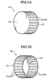
- a muffler 1A includes a cylindrical shell 2, with two circular end plates 3, 4 closing both ends of the shell 2.
- the shell 2 and end plates 3, 4 define a space hermetically sealed inside of them.
- the space is separated into four first to fourth expansion chambers 6a to 6d of a sound-absorption material by three partitions 5a, 5b and 5c.
- the end plate 3 of first chamber 6a has a hole 3a connected to an inlet 7a of an upstream discharge pipe 7.
- the other end of discharge pipe 7 is connected to a fuel cell 100 (not Illustrated in Fig.).
- An exhaust gas from the fuel cell 100 flows into the first expansion chamber 6a through discharge pipe 7.
- the muffler 1A includes a downstream discharge pipe 8 with an end that passes through a hole 4a of the end plate 4 of the fourth expansion chamber 6d and respective three partitions 5a to 5c.
- the inlet 8a of discharge pipe 8 is positioned to face the first expansion chamber 6a.
- the discharge pipe 8 extends between the second, third, and fourth chambers 6b, 6c, and 6d, with a circumferential wall having a mesh 9 formed with holes.
- An exhaust gas flows into or out between the second to fourth expansion chambers 6b to 6d through mesh 9.
- the first expansion chamber 6a houses a moisture-remover 10 therein.
- the moisture-remover 10 is located to enclose the inlet 7a of discharge pipe 7. As illustrated in Figs.
- the moisture-remover 10 includes a cylindrical pipe 11 formed radially with holes 11a.
- the moisture-remover 10 includes a hole-free closed plate 12 located to face the inlet 7a of discharge pipe 7.
- the closed plate 12 is fixed to and closes off the circular end of moisture-remover 10.
- the shell 2 has an outlet 13 in the first expansion chamber 6a at the lowermost part in a vertical direction.
- the outlet 13 may be located at any portions on the shell 2 of the expansion chamber 6a in a radial or transverse direction of the shell 2.
- the outlet 13 may be located to or extend between at least one of first, second, third and fourth expansion chambers 6a, 6b, 6c and 6d.
- the outlet 13 may be shaped as a circle, a triangle, a rectangle, a polygon or other configuration.
- An exhaust gas with moisture flows from a fuel cell 100 into the first expansion chamber 6a through the discharge pipe 7.
- the exhaust gas disperses in a space inside of the first expansion chamber 6a.
- the exhaust gas flows into the second to fourth expansion chambers 6b to 6d, while dispersing.
- the exhaust gas collides against the shell 2 or end plates 3, 4, of a sound-absorption material, thus being damped.
- the exhaust gas flowing from discharge pipe 7 into first expansion chamber 6a, collides against the closed plate 12, while dispersing. Lower temperaturization during gas dispersion and collision against the closed plate 12 accelerate to condense the moisture in the exhaust gas.
- the exhaust gas, colliding against closed plate 12 is discharged from the moisture-remover 10 through the holes 11a of pipe 11 to collide against the inner wall of shell 2 at the first chamber 6a. The collision accelerates to condense moisture in the exhaust gas.
- the first expansion chamber 6a stores drain to be discharged from the outlet 13.
- the exhaust gas travels downstream, while flowing into and out of the second to fourth expansion chambers 6b to 6d, repeatedly. Finally, the exhaust gas is discharged to outside air through the discharge pipe 8.
- the operation reduces moisture content mixed with the exhaust gas in the muffler 1A, preventing water-jump from discharge pipe 8.
- the muffler 1A does not store a drain therein, and maintains stable sound-damping performance.
- the moisture-remover 10 in the first expansion chamber 6a condenses moisture in the exhaust gas. This further reduces moisture content mixed in the exhaust gas, effectively preventing water-jump.
- An exhaust gas passes through holes 11a to be arranged in streams, reducing airflow noise and pressure loss of the exhaust gas.
- the moisture-remover may have another structure other than the aforementioned, which can separate and condense moisture from the exhaust gas.
- the moisture-remover 10 has the cylindrical pipe 11, which radially discharges exhaust gas from the holes 11a of the pipe 11 toward the inner wall of shell 2 at the first expansion chamber 6a. This smoothes a flow of the exhaust gas and further reduces airflow noise and pressure loss.
- the pipe 11 may have another shape other than a cylindrical shape.
- a muffler 1B according to the second embodiment is described.
- the muffler 1B is characterized by communication holes 14a, 14b, 14c formed at respective lower positions of partitions 5a, 5b, 5c.
- the muffler 1B includes other constitutions similar to the muffler 1A.
- Like members are designated by like reference characters in Figs, with the descriptions omitted.
- the muffler 1B reduces moisture content mixed in an exhaust gas, preventing water-jump. Without requiring storing drain inside, the muffler 1B maintains stable sound-damping performance.
- a drain stored in the second to fourth expansion chambers 6b to 6d flows into the first expansion chamber, and is discharged from the outlet 13.
- the muffler 1B further reduces drain volume, and further maintains stable sound-damping performance.
- the outlet 13 is connected to an end of a small-sized tube 15.
- a drain in the first expansion chamber 6a is discharged from outlet 13 through the tube 15. It is preferable to use the tube 15 having a smaller size in view of sound-damping performance.
- the drainage structure reduces noise (pulse- stream noise, airflow noise, whistle noise or the like) from outlet 13.
- the tube 15 has an arbitrarily positioned opening at the other end, which facilitates taking measures against water-jump of drain discharged from outlet 13.
- the outlet 13 may have an open/close valve or a lid.
- the structure reduces noise (pulse-stream noise, airflow noise), and, in addition, allows appropriate selection of drainage timing for easy measures against water-jump.
- the aforementioned first and second embodiments have mufflers 1A, 1B separated into the first to fourth expansion chambers 6a to 6d inside thereof.
- the mufflers 1A, 1B may be separated into two, three, or five or more chambers, and may be appropriately changed in design in accordance with an object of sound-damping.
- the discharge pipe includes a muffler midstream thereof.
- the storing of a drain in the muffler deteriorates sound-damping performance of the muffler.
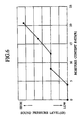
- sound absorption material used for the muffler regardless of whether high or low pitched sound, has sound-damping deterioration level which increases rapidly at a moisture content rate over 4 %, and is further increased by higher pitched sound, as shown in Figs 6 and 7.
- the moisture content rate (%) represents a value of (a volume of water) / (a volume of filled absorption material).
- the reason for the rapid increase of sound-damping deterioration level is considered to be that moisture content reduces contact surface area of the sound absorption material.
- the gas when a gas is introduced from a fuel cell into a sound-absorbing structure or an expansion chamber, the gas is dispersed to accelerate moisture Included in the gas to be condensed into a drain.
- the drain is discharged from an outlet of the sound-absorbing structure or the expansion chamber.
- a remover separates moisture from the gas. This reduces moisture content mixed in the gas, thus preventing water-jump from a discharge pipe.
- a gas is introduced into the expansion chamber to collide against a closed wall.
- the collision allows moisture to be . separated from the gas.
- the gas is discharged from holes of a tube to collide against an inner wall of the expansion chamber.
- the collision allows moisture in the gas to be condensed and separated therefrom.
- the operation permits the remover to separate moisture from the gas.
- the gas is arranged in streams through the holes, thus reducing airflow noise and pressure loss.
- the gas is discharged radially toward an inner wall of the expansion chamber through the holes. This permits the gas to be smoothly discharged, thus reducing airflow noise and pressure loss.
- avolume of drain is further reduced in the muffler, which maintains stable sound-damping performance.
- a tube reduces noise from the outlet. Arbitrary positioning of the other end of the tube facilitates taking measures against water-jump to be discharged from the outlet.
Landscapes
- Engineering & Computer Science (AREA)
- Chemical & Material Sciences (AREA)
- Combustion & Propulsion (AREA)
- Mechanical Engineering (AREA)
- General Engineering & Computer Science (AREA)
- Manufacturing & Machinery (AREA)
- Life Sciences & Earth Sciences (AREA)
- Sustainable Development (AREA)
- Sustainable Energy (AREA)
- Chemical Kinetics & Catalysis (AREA)
- Electrochemistry (AREA)
- General Chemical & Material Sciences (AREA)
- Fuel Cell (AREA)
- Exhaust Silencers (AREA)
Applications Claiming Priority (2)
| Application Number | Priority Date | Filing Date | Title |
|---|---|---|---|
| JP2003013544 | 2003-01-22 | ||
| JP2003013544A JP2004225595A (ja) | 2003-01-22 | 2003-01-22 | 消音器 |
Publications (2)
| Publication Number | Publication Date |
|---|---|
| EP1447534A2 true EP1447534A2 (de) | 2004-08-18 |
| EP1447534A3 EP1447534A3 (de) | 2005-07-06 |
Family
ID=32677537
Family Applications (1)
| Application Number | Title | Priority Date | Filing Date |
|---|---|---|---|
| EP04001083A Withdrawn EP1447534A3 (de) | 2003-01-22 | 2004-01-20 | Schalldämpfer |
Country Status (3)
| Country | Link |
|---|---|
| US (1) | US20040149515A1 (de) |
| EP (1) | EP1447534A3 (de) |
| JP (1) | JP2004225595A (de) |
Cited By (4)
| Publication number | Priority date | Publication date | Assignee | Title |
|---|---|---|---|---|
| CN102278183A (zh) * | 2011-07-19 | 2011-12-14 | 南京航空航天大学 | 一种复合式结构的柴油机排气消声器 |
| EP2615677A1 (de) * | 2012-01-11 | 2013-07-17 | Samsung Electronics Co., Ltd | Hybrider Schalldämpfer mit Gas-Flüssigkeitstrennungsfunktion in Brennstoffzellensystemen |
| EP4102600A1 (de) * | 2021-06-10 | 2022-12-14 | NOVARES France | Abgasschalldämpfer für eine brennstoffzelle |
| EP4280320A3 (de) * | 2022-05-20 | 2024-02-28 | Purem GmbH | Brennstoffzellen-abgasanlage |
Families Citing this family (15)
| Publication number | Priority date | Publication date | Assignee | Title |
|---|---|---|---|---|
| JP2006087206A (ja) * | 2004-09-15 | 2006-03-30 | Toyota Motor Corp | 燃料電池車両および車両 |
| JP4464854B2 (ja) | 2005-03-24 | 2010-05-19 | トヨタ自動車株式会社 | 燃料電池用消音器 |
| KR100644969B1 (ko) | 2005-10-31 | 2006-11-14 | 한국과학기술연구원 | 소음기능을 가지는 연료전지용 가습장치 |
| KR101303497B1 (ko) * | 2006-02-02 | 2013-09-03 | 삼성에스디아이 주식회사 | 소음기를 장착한 연료전지 시스템 |
| JP2008088914A (ja) * | 2006-10-03 | 2008-04-17 | Toyota Motor Corp | 車載エンジンの排気装置 |
| US7878298B2 (en) * | 2006-12-18 | 2011-02-01 | GM Global Technology Operations LLC | Fuel-cell exhaust system |
| JP5214906B2 (ja) * | 2007-05-11 | 2013-06-19 | 本田技研工業株式会社 | 燃料電池システム |
| JP5443693B2 (ja) * | 2008-01-22 | 2014-03-19 | 本田技研工業株式会社 | 燃料電池自動車の消音器 |
| KR20130073710A (ko) * | 2011-12-23 | 2013-07-03 | 삼성전자주식회사 | 연료 전지 시스템의 소음을 저감하기 위한 소음기 |
| KR102383224B1 (ko) * | 2016-12-06 | 2022-04-05 | 현대자동차 주식회사 | 연료전지 배출 수소 농도 저감구조 |
| KR102463703B1 (ko) * | 2016-12-15 | 2022-11-07 | 현대자동차주식회사 | 배기유체 중의 물 배출장치 및 연료전지 차량용 소음기 |
| CN110500261B (zh) * | 2019-07-26 | 2024-08-27 | 郑州精益达汽车零部件有限公司 | 一种氢燃料电池系统排气消声器 |
| CN114688103A (zh) * | 2020-12-30 | 2022-07-01 | 曼胡默尔滤清器(上海)有限公司 | 一种用于燃料电池车的宽频消声器 |
| DE102022112681A1 (de) * | 2022-05-20 | 2023-11-23 | Purem GmbH | Brennstoffzellen-Abgasanlage |
| CN117449941A (zh) * | 2023-10-07 | 2024-01-26 | 上海鸿芯氢能科技有限公司 | 用于燃料汽车的储液箱 |
Family Cites Families (25)
| Publication number | Priority date | Publication date | Assignee | Title |
|---|---|---|---|---|
| US2732913A (en) * | 1956-01-31 | Q higgins | ||
| US753845A (en) * | 1903-08-07 | 1904-03-08 | Richard W Brockway | Gasolene-engine muffler. |
| US1342464A (en) * | 1919-12-02 | 1920-06-08 | Frank P Sawders | Muffler |
| US1821688A (en) * | 1929-12-20 | 1931-09-01 | Maxim Silencer Co | Silencer |
| US2059487A (en) * | 1932-10-31 | 1936-11-03 | Halsey W Taylor Company | Muffler |
| US2087411A (en) * | 1934-01-10 | 1937-07-20 | Frederick L Maytag | Means for condensing and refining exhaust gases |
| US2498979A (en) * | 1943-09-18 | 1950-02-28 | Maxim Silencer Co | Water separator silencer |
| US2416452A (en) * | 1945-01-25 | 1947-02-25 | Joseph P Marx | Muffler |
| US2721619A (en) * | 1951-08-01 | 1955-10-25 | Alpha G Cheairs | Waterproof muffler for vertical exhausts |
| US3421315A (en) * | 1966-02-01 | 1969-01-14 | Katashi Aoki | Exhaust gas purifier for automobile |
| US3548591A (en) * | 1968-09-11 | 1970-12-22 | William H Mckay | Smog control device |
| US3563029A (en) * | 1969-03-13 | 1971-02-16 | Dow Chemical Co | Muffler for removing particulate lead from exhaust gases of internal combustion engines |
| US3698875A (en) * | 1970-05-13 | 1972-10-17 | Susumu Yamada | Device for cleaning exhaust gas from internal combustion engine |
| US3635309A (en) * | 1970-09-30 | 1972-01-18 | Prvni Brnenska Strojirna | Steam or gas damper with axial and radial baffle plates |
| US3747347A (en) * | 1971-04-12 | 1973-07-24 | S Ciraolo | Pollution preventing exhaust device |
| SE415119B (sv) * | 1974-05-16 | 1980-09-08 | Katashi Aoki | Anordning for avgasrening |
| FR2313552A1 (fr) * | 1975-06-03 | 1976-12-31 | Bertin & Cie | Dispositif perfectionne de decharge pour generateur de vapeur et analogue |
| SE415791B (sv) * | 1979-01-29 | 1980-10-27 | Gunnar Valdemar Eriksson | Kombinerad ljuddempare och oljefella for tryckluftapparater |
| US4296832A (en) * | 1979-11-14 | 1981-10-27 | Nelson Industries, Inc. | Exhaust muffler |
| US4503813A (en) * | 1983-07-07 | 1985-03-12 | Combustion Control Developments Ltd. | Engine combustion control system and method employing condensation of some exhaust gas |
| US5808245A (en) * | 1995-01-03 | 1998-09-15 | Donaldson Company, Inc. | Vertical mount catalytic converter muffler |
| US6152258A (en) * | 1999-09-28 | 2000-11-28 | Brunswick Corporation | Exhaust system with silencing and water separation capability |
| JP3813427B2 (ja) * | 2000-09-22 | 2006-08-23 | 本田技研工業株式会社 | 気体燃料のガス排出構造 |
| US6868670B1 (en) * | 2003-02-28 | 2005-03-22 | Fleetguard, Inc. | Compact, reduced backpressure, vertical exhaust water trap assembly |
| US6968923B2 (en) * | 2003-07-30 | 2005-11-29 | Control Components, Inc. | Reduced noise valve stack connection |
-
2003
- 2003-01-22 JP JP2003013544A patent/JP2004225595A/ja not_active Withdrawn
-
2004
- 2004-01-20 EP EP04001083A patent/EP1447534A3/de not_active Withdrawn
- 2004-01-21 US US10/760,346 patent/US20040149515A1/en not_active Abandoned
Cited By (6)
| Publication number | Priority date | Publication date | Assignee | Title |
|---|---|---|---|---|
| CN102278183A (zh) * | 2011-07-19 | 2011-12-14 | 南京航空航天大学 | 一种复合式结构的柴油机排气消声器 |
| EP2615677A1 (de) * | 2012-01-11 | 2013-07-17 | Samsung Electronics Co., Ltd | Hybrider Schalldämpfer mit Gas-Flüssigkeitstrennungsfunktion in Brennstoffzellensystemen |
| US9038772B2 (en) | 2012-01-11 | 2015-05-26 | Samsung Sdi Co., Ltd. | Hybrid silencer with gas-liquid separating function in fuel cell system |
| EP4102600A1 (de) * | 2021-06-10 | 2022-12-14 | NOVARES France | Abgasschalldämpfer für eine brennstoffzelle |
| FR3123944A1 (fr) * | 2021-06-10 | 2022-12-16 | Novares France | Silencieux d'échappement pour une pile à combustible |
| EP4280320A3 (de) * | 2022-05-20 | 2024-02-28 | Purem GmbH | Brennstoffzellen-abgasanlage |
Also Published As
| Publication number | Publication date |
|---|---|
| EP1447534A3 (de) | 2005-07-06 |
| US20040149515A1 (en) | 2004-08-05 |
| JP2004225595A (ja) | 2004-08-12 |
Similar Documents
| Publication | Publication Date | Title |
|---|---|---|
| EP1447534A2 (de) | Schalldämpfer | |
| JP4392592B2 (ja) | 排気消音装置 | |
| JP3214338B2 (ja) | 自動車用排気消音装置 | |
| JPH073170B2 (ja) | 排気ガスマフラ | |
| CN214705422U (zh) | 一种燃料电池发动机复合型消音器 | |
| EP1908930A2 (de) | Abgasschalldämpfer für Kraftfahrzeuge | |
| KR101417128B1 (ko) | 소음기 | |
| KR100946493B1 (ko) | 자동차의 배기 소음기 | |
| JP4505114B2 (ja) | 触媒マフラ | |
| JP2006283644A (ja) | 内燃機関用マフラ | |
| US20100006370A1 (en) | Sound-attenuating muffler having reduced back pressure | |
| JP2009197590A (ja) | 消音器及び消音器の製造方法 | |
| KR100528214B1 (ko) | 머플러 구조 | |
| KR100535475B1 (ko) | 머플러의 공명소음 저감장치 | |
| JP2009209854A (ja) | 消音器 | |
| CN210396857U (zh) | 消音器和具有其的排气装置及车辆 | |
| WO2006041256A1 (en) | A silencer for vehicle | |
| JP2009257201A (ja) | 触媒内蔵型マフラ | |
| JPH11315712A (ja) | 自動車用排気消音装置 | |
| CN220015306U (zh) | 适用于非道路小型发动机的低碳消声器 | |
| US11840948B2 (en) | Silencer for an exhaust system of an internal combustion engine | |
| JP2009209856A (ja) | 消音器及び消音器の製造方法 | |
| CN120720227B (zh) | 消音器、压缩机及换热设备 | |
| JP2004137951A (ja) | 共鳴型消音器 | |
| US20250128613A1 (en) | Silencer and vehicle including the same |
Legal Events
| Date | Code | Title | Description |
|---|---|---|---|
| PUAI | Public reference made under article 153(3) epc to a published international application that has entered the european phase |
Free format text: ORIGINAL CODE: 0009012 |
|
| AK | Designated contracting states |
Kind code of ref document: A2 Designated state(s): AT BE BG CH CY CZ DE DK EE ES FI FR GB GR HU IE IT LI LU MC NL PT RO SE SI SK TR |
|
| AX | Request for extension of the european patent |
Extension state: AL LT LV MK |
|
| PUAL | Search report despatched |
Free format text: ORIGINAL CODE: 0009013 |
|
| AK | Designated contracting states |
Kind code of ref document: A3 Designated state(s): AT BE BG CH CY CZ DE DK EE ES FI FR GB GR HU IE IT LI LU MC NL PT RO SE SI SK TR |
|
| AX | Request for extension of the european patent |
Extension state: AL LT LV MK |
|
| 17P | Request for examination filed |
Effective date: 20050805 |
|
| AKX | Designation fees paid |
Designated state(s): DE FR GB |
|
| STAA | Information on the status of an ep patent application or granted ep patent |
Free format text: STATUS: THE APPLICATION IS DEEMED TO BE WITHDRAWN |
|
| 18D | Application deemed to be withdrawn |
Effective date: 20060202 |