EP1447569A1 - Vorrichtung zur Druckerzeugung - Google Patents
Vorrichtung zur Druckerzeugung Download PDFInfo
- Publication number
- EP1447569A1 EP1447569A1 EP04000839A EP04000839A EP1447569A1 EP 1447569 A1 EP1447569 A1 EP 1447569A1 EP 04000839 A EP04000839 A EP 04000839A EP 04000839 A EP04000839 A EP 04000839A EP 1447569 A1 EP1447569 A1 EP 1447569A1
- Authority
- EP
- European Patent Office
- Prior art keywords
- pressure
- compression
- pressure stages
- stages
- pistons
- Prior art date
- Legal status (The legal status is an assumption and is not a legal conclusion. Google has not performed a legal analysis and makes no representation as to the accuracy of the status listed.)
- Granted
Links
Images


Classifications
-
- F—MECHANICAL ENGINEERING; LIGHTING; HEATING; WEAPONS; BLASTING
- F04—POSITIVE - DISPLACEMENT MACHINES FOR LIQUIDS; PUMPS FOR LIQUIDS OR ELASTIC FLUIDS
- F04B—POSITIVE-DISPLACEMENT MACHINES FOR LIQUIDS; PUMPS
- F04B3/00—Machines or pumps with pistons coacting within one cylinder, e.g. multi-stage
-
- F—MECHANICAL ENGINEERING; LIGHTING; HEATING; WEAPONS; BLASTING
- F04—POSITIVE - DISPLACEMENT MACHINES FOR LIQUIDS; PUMPS FOR LIQUIDS OR ELASTIC FLUIDS
- F04B—POSITIVE-DISPLACEMENT MACHINES FOR LIQUIDS; PUMPS
- F04B25/00—Multi-stage pumps
-
- F—MECHANICAL ENGINEERING; LIGHTING; HEATING; WEAPONS; BLASTING
- F04—POSITIVE - DISPLACEMENT MACHINES FOR LIQUIDS; PUMPS FOR LIQUIDS OR ELASTIC FLUIDS
- F04B—POSITIVE-DISPLACEMENT MACHINES FOR LIQUIDS; PUMPS
- F04B25/00—Multi-stage pumps
- F04B25/02—Multi-stage pumps of stepped piston type
Definitions
- the invention relates to a device for generating pressure, the at least two pressure stages connected in series Compression of a gas and at each pressure level is provided with at least one piston which in a Compression cylinder is guided.
- Such devices are often used to make a Gas from an ambient pressure to a high pressure level to compress.
- the use of several in a row switched pressure levels leads to an increase the process effectiveness over single-stage compressors.
- the known multi-stage compressors have in usually a large volume and a high operating volume on.
- the vast majority are known multi-stage compressor intended large delivery volume at relatively low pressures to create.
- the object of the present invention is a device of the type mentioned in the introduction in such a way that a compact device design with high efficiency is provided becomes.
- a simple movement coupling of the pistons is supported that the pressure stages face away from each other Sides of the valve block are arranged.
- An advantageous compression is supported in that the first pressure stage with a relative to a compression space the second pressure stage larger compression space is provided.
- a typical dimensioning is that the series connection of the pressure levels for compression on Pressure level of about 200 bar are formed.
- a mechanical drive is provided in that the pistons are connected to a crank drive.
- Another drive variant is that the pistons are connected to a pneumatic drive.
- the design of the compressor makes it especially suitable for the pressure stages for compression are formed by oxygen.
- a storage of the volume generated by the compressor compressed gas can be done in that the pressure levels trained for filling compressed gas cylinders are.
- a preferred area of application is opened up by that the pressure levels for use in the field of ventilation technology are trained.
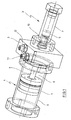
- the device for generating pressure with a first pressure stage (1) and a second pressure stage (2) is.
- the pressure stages (1, 2) are facing away from each other Sides of a valve block (3) arranged.
- Each of the Pressure stages (1, 2) is equipped with a piston (4, 5), which is guided in a compression cylinder (6, 7).
- the pistons (4, 5) are interconnected by a piston rod (8) connected.
- Each of the pressure stages (1, 2) has a compression space (9, 10).
- the gas to be compressed becomes the device supplied via an input connection (11).
- the compressed Gas is discharged via an outlet connection (12).
- Figure 2 illustrates in a cross-sectional view Structure of the device.
- the piston rod (8) via a bearing (13) is guided in the area of the valve block (3).
- the warehouse (13) has seals to prevent gas transfer between to prevent the pressure levels (1, 2).
- a connection channel runs within the valve block (3) (14) to gas from the first pressure stage (1) to the second To conduct pressure stage (2).
- the connecting channel (14) is with a check valve (15) to prevent gas backflow to prevent compression in the compression space (10).
- Figure 3 shows the arrangement of Figure 1 in an opposite Figure 2 section plane rotated by 90 °.
- the representation shows the input connection (11) and the output connection (12) recognizable.
- Output channel (16) is a check valve (17) arranged to backflow the compressed gas from the outlet connection (12) into the compression space (10) to avoid.
- a compressed gas cylinder can be connected at the output connection (12)
- the device can be driven in different ways and way.
- a pneumatic drive is realized.
- An introduction of the mechanical kinetic energy can for example have a not shown Drive rod take place, which is screwed into the piston (4) becomes.
- the piston (4) has a threaded hole (18) provided for coupling to other components.
- a compression process is carried out in such a way that initially a return stroke of the piston (4) takes place the piston (4) is removed from the valve block (3).
- the thing to be compressed Gas flows through the inlet port (11) into the compression space (9).
- the piston (4) in the direction on the valve block (3) moves and compresses the gas inside the compression space (9).
- the piston (5) leads simultaneously a movement that moves away from the valve block (3) removed.
- the gas compressed by the piston (4) thus flows into the Compression room (10). After completing this compression movement the pistons (4, 5) move again in the opposite direction. The piston (5) compresses here the gas inside the compression space (10). A backflow is through the check valve (15) prevented. The compressed gas from the area of Compression space (10) is via the output connection (12) directed to an intended receiving device. In the compression room (9) thus precompaction takes place Compression chamber (10) is used for the main compression.
- the device explained in the drawings is particular suitable for applications in the field of medical technology, because both a small construction volume and low operating noise can be achieved.
- one Intended for use by an oxygen concentrator provided oxygen compressed and a compressed gas bottle is fed.
- the compressed gas bottle is used for a mobile oxygen supply for a patient.
- Filter elements can be found in the areas of the check valves (15) used to contaminate the valves to be avoided by small abrasion particles of the seals, which negatively affect the function of the valves can.
Landscapes
- Engineering & Computer Science (AREA)
- Mechanical Engineering (AREA)
- General Engineering & Computer Science (AREA)
- Compressors, Vaccum Pumps And Other Relevant Systems (AREA)
- Compressor (AREA)
- Electrical Discharge Machining, Electrochemical Machining, And Combined Machining (AREA)
Abstract
Description
- Fig. 1
- eine perspektivische Darstellung einer zweistufigen Verdichtungsvorrichtung, bei der zwischen den beiden Druckstufen ein Ventilblock angeordnet ist,
- Fig. 2
- einen Vertikalschnitt durch die Anordnung gemäß Fig. 1 und
- Fig. 3
- einen weiteren Längsschnitt durch die Anordnung gemäß Fig. 1.
Claims (12)
- Vorrichtung zur Druckerzeugung, die mindestens zwei in Reihe geschaltete Druckstufen zur Komprimierung eines Gases aufweist und bei der jede Druckstufe mit mindestens einem Kolben versehen ist, der in einem Kompressionszylinder geführt ist, dadurch gekennzeichnet, daß die Druckstufen (1, 2) über einen ventilblock (3) miteinander gekoppelt sind, der zwischen den Druckstufen (1, 2) angeordnet ist und daß Längsachsen der Kolben (4, 5) im wesentlichen auf einer gemeinsamen Geraden verlaufen.
- Vorrichtung nach Anspruch 1, dadurch gekennzeichnet, daß die Druckstufen (1, 2) auf einander abgewandten Seiten des Ventilblockes (3) angeordnet sind.
- Vorrichtung nach Anspruch 1 oder 2, dadurch gekennzeichnet, daß die erste Druckstufe (1) mit einem relativ zu einem Kompressionsraum (10) der zweiten Druckstufe (2) größer dimensionierten Kompressionsraum (9) versehen ist.
- vorrichtung nach einem der Ansprüche 1 bis 3, dadurch gekennzeichnet, daß die Druckstufen (1, 2) von einem Verbindungskanal (14) miteinander verbunden sind, in dessen Bereich ein Rückschlagventil (15) angeordnet ist.
- Vorrichtung nach einem der Ansprüche 1 bis 4, dadurch gekennzeichnet, daß die Kolben (4, 5) zur Durchführung von zeitlich phasenversetzt verlaufenden Kompressionsvorgängen in den Druckstufen (1, 2) von einer Kolbenstange (8) starr miteinander verbunden sind.
- Vorrichtung nach einem der Ansprüche 1 bis 5, dadurch gekennzeichnet, daß die Reihenschaltung der Druckstufen (1, 2) für eine verdichtung auf ein Druckniveau von etwa 200 bar ausgebildet sind.
- vorrichtung nach einem der Ansprüche 1 bis 6, dadurch gekennzeichnet, daß die Druckstufen (1, 2) für eine Durchflußmenge von etwa 1 Liter pro Minute an der ersten Druckstufe (1) zugeführtem unkomprimierten Gas ausgebildet sind.
- Vorrichtung nach einem der Ansprüche 1 bis 7, dadurch gekennzeichnet, daß die Kolben (4, 5) mit einem Kurbelantrieb verbunden sind.
- Vorrichtung nach einem der Ansprüche 1 bis 7, dadurch gekennzeichnet, daß die Kolben (4, 5) mit einem pneumatischen Antrieb verbunden sind.
- Vorrichtung nach einem der Ansprüche 1 bis 9, dadurch gekennzeichnet, daß die Druckstufen (1, 2) zur Komprimierung von Sauerstoff ausgebildet sind.
- Vorrichtung nach einem der Ansprüche 1 bis 10, dadurch gekennzeichnet, daß die Druckstufen (1, 2) für eine Befüllung von Druckgasflaschen ausgebildet sind.
- Vorrichtung nach einem der Ansprüche 1 bis 11, dadurch gekennzeichnet, daß die Druckstufen (1, 2) für eine Verwendung im Bereich der Beatmungstechnik ausgebildet sind.
Applications Claiming Priority (2)
| Application Number | Priority Date | Filing Date | Title |
|---|---|---|---|
| DE10302690 | 2003-01-24 | ||
| DE10302690A DE10302690A1 (de) | 2003-01-24 | 2003-01-24 | Vorrichtung zur Druckerzeugung |
Publications (2)
| Publication Number | Publication Date |
|---|---|
| EP1447569A1 true EP1447569A1 (de) | 2004-08-18 |
| EP1447569B1 EP1447569B1 (de) | 2006-02-15 |
Family
ID=32667795
Family Applications (1)
| Application Number | Title | Priority Date | Filing Date |
|---|---|---|---|
| EP04000839A Expired - Lifetime EP1447569B1 (de) | 2003-01-24 | 2004-01-16 | Vorrichtung zur Druckerzeugung |
Country Status (3)
| Country | Link |
|---|---|
| EP (1) | EP1447569B1 (de) |
| AT (1) | ATE317945T1 (de) |
| DE (2) | DE10302690A1 (de) |
Cited By (2)
| Publication number | Priority date | Publication date | Assignee | Title |
|---|---|---|---|---|
| EP2714167A4 (de) * | 2011-05-24 | 2015-06-24 | Invacare Corp | Sauerstoffverdichter mit verstärkungsstufe |
| US9624918B2 (en) | 2012-02-03 | 2017-04-18 | Invacare Corporation | Pumping device |
Families Citing this family (2)
| Publication number | Priority date | Publication date | Assignee | Title |
|---|---|---|---|---|
| DE102016107130A1 (de) * | 2016-04-18 | 2017-10-19 | Thomas Richter | Pumpe zum Verdichten eines Fluids |
| DE102017004088A1 (de) | 2017-04-28 | 2018-10-31 | Wabco Gmbh | Verdichter, Druckluftversorgungsanlage zum Betreiben einer Pneumatikanlage und Verfahren zum Betreiben einer Druckluftversorgungsanlage |
Citations (6)
| Publication number | Priority date | Publication date | Assignee | Title |
|---|---|---|---|---|
| US236992A (en) * | 1881-01-25 | gushier | ||
| US464223A (en) * | 1891-12-01 | Ernest c | ||
| DE415355C (de) * | 1922-01-09 | 1925-06-18 | John Bartram Whitted | Luftpumpe |
| US2034159A (en) * | 1932-11-10 | 1936-03-17 | Everett W Swartwout | Compressor |
| US4639197A (en) * | 1984-07-20 | 1987-01-27 | Jean Tornare | Pump for cryogenic fluids |
| US5984642A (en) * | 1994-06-06 | 1999-11-16 | Flow Holdings Gmbh (Sagl) Limited Liability Co. | Pressure intensifier |
-
2003
- 2003-01-24 DE DE10302690A patent/DE10302690A1/de not_active Withdrawn
-
2004
- 2004-01-16 EP EP04000839A patent/EP1447569B1/de not_active Expired - Lifetime
- 2004-01-16 AT AT04000839T patent/ATE317945T1/de not_active IP Right Cessation
- 2004-01-16 DE DE502004000286T patent/DE502004000286D1/de not_active Expired - Fee Related
Patent Citations (6)
| Publication number | Priority date | Publication date | Assignee | Title |
|---|---|---|---|---|
| US236992A (en) * | 1881-01-25 | gushier | ||
| US464223A (en) * | 1891-12-01 | Ernest c | ||
| DE415355C (de) * | 1922-01-09 | 1925-06-18 | John Bartram Whitted | Luftpumpe |
| US2034159A (en) * | 1932-11-10 | 1936-03-17 | Everett W Swartwout | Compressor |
| US4639197A (en) * | 1984-07-20 | 1987-01-27 | Jean Tornare | Pump for cryogenic fluids |
| US5984642A (en) * | 1994-06-06 | 1999-11-16 | Flow Holdings Gmbh (Sagl) Limited Liability Co. | Pressure intensifier |
Cited By (2)
| Publication number | Priority date | Publication date | Assignee | Title |
|---|---|---|---|---|
| EP2714167A4 (de) * | 2011-05-24 | 2015-06-24 | Invacare Corp | Sauerstoffverdichter mit verstärkungsstufe |
| US9624918B2 (en) | 2012-02-03 | 2017-04-18 | Invacare Corporation | Pumping device |
Also Published As
| Publication number | Publication date |
|---|---|
| EP1447569B1 (de) | 2006-02-15 |
| ATE317945T1 (de) | 2006-03-15 |
| DE502004000286D1 (de) | 2006-04-20 |
| DE10302690A1 (de) | 2004-08-12 |
Similar Documents
| Publication | Publication Date | Title |
|---|---|---|
| DE3147824C2 (de) | Mehrstufige Drehkolben-Vakuumpumpe | |
| DE102005052873B4 (de) | Kolbenverdichter und Kältemaschine mit demselben | |
| WO2008022916A1 (de) | Verfahren zur abreaktion selbstentzündlicher stäube in einer vakuumpumpvorrichtung | |
| DE112007000125B4 (de) | Hochdruck-Kompressor sowie dessen Verwendung und Verfahren zu dessen Betrieb | |
| WO2007137941A1 (de) | Radialkolbenpumpe zur kraftstoff-hochdruckversorgung bei einer brennkraftmaschine | |
| EP1447569B1 (de) | Vorrichtung zur Druckerzeugung | |
| EP0925445A1 (de) | Radialkolbenpumpe zur kraftstoffhochdruckversorgung | |
| EP2710263B1 (de) | Kompressorvorrichtung sowie eine damit ausgerüstete kühlvorrichtung und eine damit ausgerüstete kältemaschine | |
| EP3728846B1 (de) | Vorrichtung und verfahren zum verdichten eines arbeitsmediums | |
| EP2464868A1 (de) | Membranmaschine | |
| DE4042242A1 (de) | Kompressor fuer gas, oel o. dgl. | |
| EP2246567B1 (de) | Kolbenverdichter | |
| EP3835579A1 (de) | Kompressor und verfahren zur förderung und verdichtung eines förderfluids in ein zielsystem | |
| DE10249042A1 (de) | Verdichtersaugventilzusammenbau | |
| EP0373229A1 (de) | Mechanische Vakuumpumpe mit einer federbelasteten Rückschlagklappe | |
| EP1812759A1 (de) | Kombinierter kolben-expander-verdichter | |
| DE102005037537A1 (de) | Kolbenpumpe mit wenigstens einem Kolbenelement | |
| WO2004106739A1 (de) | Vakuum-kolbenpumpe | |
| EP4431736B1 (de) | Doppelkolbenpumpvorrichtung | |
| DD269881A1 (de) | Kolbenverdichter | |
| EP1886023B1 (de) | Kryoverdichter mit seitlich angeordnetem druckventil | |
| DE4244063A1 (de) | Wälzkolben-Vakuumpumpe | |
| DE4318737C2 (de) | Drehkolbenkompressor | |
| DE314498C (de) | ||
| EP1843040A2 (de) | Verfahren zum Betreiben einer oszillierenden Verdrängerpumpe und oszillierende Verdrängerpumpe |
Legal Events
| Date | Code | Title | Description |
|---|---|---|---|
| PUAI | Public reference made under article 153(3) epc to a published international application that has entered the european phase |
Free format text: ORIGINAL CODE: 0009012 |
|
| AK | Designated contracting states |
Kind code of ref document: A1 Designated state(s): AT BE BG CH CY CZ DE DK EE ES FI FR GB GR HU IE IT LI LU MC NL PT RO SE SI SK TR |
|
| AX | Request for extension of the european patent |
Extension state: AL LT LV MK |
|
| 17P | Request for examination filed |
Effective date: 20040731 |
|
| 17Q | First examination report despatched |
Effective date: 20041008 |
|
| AKX | Designation fees paid |
Designated state(s): AT BE BG CH CY CZ DE DK EE ES FI FR GB GR HU IE IT LI LU MC NL PT RO SE SI SK TR |
|
| GRAP | Despatch of communication of intention to grant a patent |
Free format text: ORIGINAL CODE: EPIDOSNIGR1 |
|
| GRAS | Grant fee paid |
Free format text: ORIGINAL CODE: EPIDOSNIGR3 |
|
| GRAA | (expected) grant |
Free format text: ORIGINAL CODE: 0009210 |
|
| AK | Designated contracting states |
Kind code of ref document: B1 Designated state(s): AT BE BG CH CY CZ DE DK EE ES FI FR GB GR HU IE IT LI LU MC NL PT RO SE SI SK TR |
|
| PG25 | Lapsed in a contracting state [announced via postgrant information from national office to epo] |
Ref country code: IT Free format text: LAPSE BECAUSE OF FAILURE TO SUBMIT A TRANSLATION OF THE DESCRIPTION OR TO PAY THE FEE WITHIN THE PRESCRIBED TIME-LIMIT;WARNING: LAPSES OF ITALIAN PATENTS WITH EFFECTIVE DATE BEFORE 2007 MAY HAVE OCCURRED AT ANY TIME BEFORE 2007. THE CORRECT EFFECTIVE DATE MAY BE DIFFERENT FROM THE ONE RECORDED. Effective date: 20060215 Ref country code: NL Free format text: LAPSE BECAUSE OF FAILURE TO SUBMIT A TRANSLATION OF THE DESCRIPTION OR TO PAY THE FEE WITHIN THE PRESCRIBED TIME-LIMIT Effective date: 20060215 Ref country code: RO Free format text: LAPSE BECAUSE OF FAILURE TO SUBMIT A TRANSLATION OF THE DESCRIPTION OR TO PAY THE FEE WITHIN THE PRESCRIBED TIME-LIMIT Effective date: 20060215 Ref country code: SI Free format text: LAPSE BECAUSE OF FAILURE TO SUBMIT A TRANSLATION OF THE DESCRIPTION OR TO PAY THE FEE WITHIN THE PRESCRIBED TIME-LIMIT Effective date: 20060215 Ref country code: IE Free format text: LAPSE BECAUSE OF FAILURE TO SUBMIT A TRANSLATION OF THE DESCRIPTION OR TO PAY THE FEE WITHIN THE PRESCRIBED TIME-LIMIT Effective date: 20060215 Ref country code: GB Free format text: LAPSE BECAUSE OF FAILURE TO SUBMIT A TRANSLATION OF THE DESCRIPTION OR TO PAY THE FEE WITHIN THE PRESCRIBED TIME-LIMIT Effective date: 20060215 Ref country code: FI Free format text: LAPSE BECAUSE OF FAILURE TO SUBMIT A TRANSLATION OF THE DESCRIPTION OR TO PAY THE FEE WITHIN THE PRESCRIBED TIME-LIMIT Effective date: 20060215 Ref country code: SK Free format text: LAPSE BECAUSE OF FAILURE TO SUBMIT A TRANSLATION OF THE DESCRIPTION OR TO PAY THE FEE WITHIN THE PRESCRIBED TIME-LIMIT Effective date: 20060215 |
|
| REG | Reference to a national code |
Ref country code: CH Ref legal event code: EP Ref country code: GB Ref legal event code: FG4D Free format text: NOT ENGLISH |
|
| REG | Reference to a national code |
Ref country code: IE Ref legal event code: FG4D Free format text: LANGUAGE OF EP DOCUMENT: GERMAN |
|
| REF | Corresponds to: |
Ref document number: 502004000286 Country of ref document: DE Date of ref document: 20060420 Kind code of ref document: P |
|
| PG25 | Lapsed in a contracting state [announced via postgrant information from national office to epo] |
Ref country code: DK Free format text: LAPSE BECAUSE OF FAILURE TO SUBMIT A TRANSLATION OF THE DESCRIPTION OR TO PAY THE FEE WITHIN THE PRESCRIBED TIME-LIMIT Effective date: 20060515 Ref country code: BG Free format text: LAPSE BECAUSE OF FAILURE TO SUBMIT A TRANSLATION OF THE DESCRIPTION OR TO PAY THE FEE WITHIN THE PRESCRIBED TIME-LIMIT Effective date: 20060515 Ref country code: SE Free format text: LAPSE BECAUSE OF FAILURE TO SUBMIT A TRANSLATION OF THE DESCRIPTION OR TO PAY THE FEE WITHIN THE PRESCRIBED TIME-LIMIT Effective date: 20060515 |
|
| PG25 | Lapsed in a contracting state [announced via postgrant information from national office to epo] |
Ref country code: ES Free format text: LAPSE BECAUSE OF FAILURE TO SUBMIT A TRANSLATION OF THE DESCRIPTION OR TO PAY THE FEE WITHIN THE PRESCRIBED TIME-LIMIT Effective date: 20060526 |
|
| PG25 | Lapsed in a contracting state [announced via postgrant information from national office to epo] |
Ref country code: PT Free format text: LAPSE BECAUSE OF FAILURE TO SUBMIT A TRANSLATION OF THE DESCRIPTION OR TO PAY THE FEE WITHIN THE PRESCRIBED TIME-LIMIT Effective date: 20060717 |
|
| NLV1 | Nl: lapsed or annulled due to failure to fulfill the requirements of art. 29p and 29m of the patents act | ||
| GBV | Gb: ep patent (uk) treated as always having been void in accordance with gb section 77(7)/1977 [no translation filed] |
Effective date: 20060215 |
|
| REG | Reference to a national code |
Ref country code: IE Ref legal event code: FD4D |
|
| ET | Fr: translation filed | ||
| PLBE | No opposition filed within time limit |
Free format text: ORIGINAL CODE: 0009261 |
|
| STAA | Information on the status of an ep patent application or granted ep patent |
Free format text: STATUS: NO OPPOSITION FILED WITHIN TIME LIMIT |
|
| 26N | No opposition filed |
Effective date: 20061116 |
|
| PG25 | Lapsed in a contracting state [announced via postgrant information from national office to epo] |
Ref country code: MC Free format text: LAPSE BECAUSE OF NON-PAYMENT OF DUE FEES Effective date: 20070131 |
|
| BERE | Be: lapsed |
Owner name: WEINMANN GERATE FUR MEDIZIN G.M.B.H. & CO. KG Effective date: 20070131 |
|
| PG25 | Lapsed in a contracting state [announced via postgrant information from national office to epo] |
Ref country code: BE Free format text: LAPSE BECAUSE OF NON-PAYMENT OF DUE FEES Effective date: 20070131 |
|
| PG25 | Lapsed in a contracting state [announced via postgrant information from national office to epo] |
Ref country code: GR Free format text: LAPSE BECAUSE OF FAILURE TO SUBMIT A TRANSLATION OF THE DESCRIPTION OR TO PAY THE FEE WITHIN THE PRESCRIBED TIME-LIMIT Effective date: 20060516 Ref country code: CZ Free format text: LAPSE BECAUSE OF FAILURE TO SUBMIT A TRANSLATION OF THE DESCRIPTION OR TO PAY THE FEE WITHIN THE PRESCRIBED TIME-LIMIT Effective date: 20060215 |
|
| PGFP | Annual fee paid to national office [announced via postgrant information from national office to epo] |
Ref country code: DE Payment date: 20071121 Year of fee payment: 5 Ref country code: IT Payment date: 20080130 Year of fee payment: 5 |
|
| PG25 | Lapsed in a contracting state [announced via postgrant information from national office to epo] |
Ref country code: AT Free format text: LAPSE BECAUSE OF NON-PAYMENT OF DUE FEES Effective date: 20070116 |
|
| PG25 | Lapsed in a contracting state [announced via postgrant information from national office to epo] |
Ref country code: EE Free format text: LAPSE BECAUSE OF FAILURE TO SUBMIT A TRANSLATION OF THE DESCRIPTION OR TO PAY THE FEE WITHIN THE PRESCRIBED TIME-LIMIT Effective date: 20060215 |
|
| PGFP | Annual fee paid to national office [announced via postgrant information from national office to epo] |
Ref country code: FR Payment date: 20071220 Year of fee payment: 5 |
|
| REG | Reference to a national code |
Ref country code: CH Ref legal event code: PL |
|
| PG25 | Lapsed in a contracting state [announced via postgrant information from national office to epo] |
Ref country code: CH Free format text: LAPSE BECAUSE OF NON-PAYMENT OF DUE FEES Effective date: 20080131 Ref country code: LI Free format text: LAPSE BECAUSE OF NON-PAYMENT OF DUE FEES Effective date: 20080131 |
|
| PG25 | Lapsed in a contracting state [announced via postgrant information from national office to epo] |
Ref country code: LU Free format text: LAPSE BECAUSE OF NON-PAYMENT OF DUE FEES Effective date: 20070116 Ref country code: CY Free format text: LAPSE BECAUSE OF FAILURE TO SUBMIT A TRANSLATION OF THE DESCRIPTION OR TO PAY THE FEE WITHIN THE PRESCRIBED TIME-LIMIT Effective date: 20060215 |
|
| PG25 | Lapsed in a contracting state [announced via postgrant information from national office to epo] |
Ref country code: TR Free format text: LAPSE BECAUSE OF FAILURE TO SUBMIT A TRANSLATION OF THE DESCRIPTION OR TO PAY THE FEE WITHIN THE PRESCRIBED TIME-LIMIT Effective date: 20060215 Ref country code: HU Free format text: LAPSE BECAUSE OF FAILURE TO SUBMIT A TRANSLATION OF THE DESCRIPTION OR TO PAY THE FEE WITHIN THE PRESCRIBED TIME-LIMIT Effective date: 20060816 |
|
| PG25 | Lapsed in a contracting state [announced via postgrant information from national office to epo] |
Ref country code: DE Free format text: LAPSE BECAUSE OF NON-PAYMENT OF DUE FEES Effective date: 20090801 |
|
| REG | Reference to a national code |
Ref country code: FR Ref legal event code: ST Effective date: 20091030 |
|
| PG25 | Lapsed in a contracting state [announced via postgrant information from national office to epo] |
Ref country code: FR Free format text: LAPSE BECAUSE OF NON-PAYMENT OF DUE FEES Effective date: 20090202 |