EP1447679A2 - Dispositif et procédé pour mesurer la distance entre deux points d'un objet, en particulier pour mesurer le diamètre d'une roue d'un véhicule ferroviaire - Google Patents
Dispositif et procédé pour mesurer la distance entre deux points d'un objet, en particulier pour mesurer le diamètre d'une roue d'un véhicule ferroviaire Download PDFInfo
- Publication number
- EP1447679A2 EP1447679A2 EP04002890A EP04002890A EP1447679A2 EP 1447679 A2 EP1447679 A2 EP 1447679A2 EP 04002890 A EP04002890 A EP 04002890A EP 04002890 A EP04002890 A EP 04002890A EP 1447679 A2 EP1447679 A2 EP 1447679A2
- Authority
- EP
- European Patent Office
- Prior art keywords
- wheel
- point
- rail
- distance
- diameter
- Prior art date
- Legal status (The legal status is an assumption and is not a legal conclusion. Google has not performed a legal analysis and makes no representation as to the accuracy of the status listed.)
- Granted
Links
Images

Classifications
-
- G—PHYSICS
- G01—MEASURING; TESTING
- G01B—MEASURING LENGTH, THICKNESS OR SIMILAR LINEAR DIMENSIONS; MEASURING ANGLES; MEASURING AREAS; MEASURING IRREGULARITIES OF SURFACES OR CONTOURS
- G01B7/00—Measuring arrangements characterised by the use of electric or magnetic techniques
- G01B7/12—Measuring arrangements characterised by the use of electric or magnetic techniques for measuring diameters
- G01B7/125—Measuring arrangements characterised by the use of electric or magnetic techniques for measuring diameters of objects while moving
-
- B—PERFORMING OPERATIONS; TRANSPORTING
- B61—RAILWAYS
- B61L—GUIDING RAILWAY TRAFFIC; ENSURING THE SAFETY OF RAILWAY TRAFFIC
- B61L1/00—Devices along the route controlled by interaction with the vehicle or train
- B61L1/20—Safety arrangements for preventing or indicating malfunction of the device, e.g. by leakage current, by lightning
-
- G—PHYSICS
- G01—MEASURING; TESTING
- G01B—MEASURING LENGTH, THICKNESS OR SIMILAR LINEAR DIMENSIONS; MEASURING ANGLES; MEASURING AREAS; MEASURING IRREGULARITIES OF SURFACES OR CONTOURS
- G01B11/00—Measuring arrangements characterised by the use of optical techniques
- G01B11/08—Measuring arrangements characterised by the use of optical techniques for measuring diameters
- G01B11/10—Measuring arrangements characterised by the use of optical techniques for measuring diameters of objects while moving
- G01B11/105—Measuring arrangements characterised by the use of optical techniques for measuring diameters of objects while moving using photoelectric detection means
-
- G—PHYSICS
- G01—MEASURING; TESTING
- G01S—RADIO DIRECTION-FINDING; RADIO NAVIGATION; DETERMINING DISTANCE OR VELOCITY BY USE OF RADIO WAVES; LOCATING OR PRESENCE-DETECTING BY USE OF THE REFLECTION OR RERADIATION OF RADIO WAVES; ANALOGOUS ARRANGEMENTS USING OTHER WAVES
- G01S11/00—Systems for determining distance or velocity not using reflection or reradiation
- G01S11/12—Systems for determining distance or velocity not using reflection or reradiation using electromagnetic waves other than radio waves
Definitions
- the invention relates to a device for measuring the distance two points of a measurement object, especially for measurement the wheel diameter of a rail-bound vehicle wheel, according to the preamble of claim 1, and a Method according to the preamble of patent claim 16.
- Such a device is used in particular for contactless Measurement of a distance on a device or vehicle part.
- This can be the length of the device part or the diameter of a vehicle wheel, its characteristic value for safety of a plant or system is important.
- This Wheel and axle loads are nowadays often passed through a weigh-in recorded on the track and compared to the specified Values monitored.
- a weigh-in recorded on the track Especially in international train traffic but drive very different types of vehicles and wagons on the track, which are also different permissible Have axle loads. But for this it is necessary that.
- the invention is therefore based on the object of characteristic values to determine a moving rail vehicle from which clear maximum permissible wheel or axle loads can be derived.
- the invention is based on the knowledge that the maximum permissible Wheel or axle load essentially by the respective Wheel size can be determined. That's why by simply determining the wheel size the respective maximum permissible bike or Axle load specified and can be done by a simple comparison are monitored with the determined wheel or axle load. It it is conceivable to measure the wheel size by manual length measurement to be carried out, but this is only for standing Rail vehicles possible. That is why it is desirable that Wheel size through an automated measurement process during the Carry out crossing on the track.
- Optical measuring methods are known by means of which a non-contact Length measurement is possible, but so far Not yet determining the wheel size on rolling rail wheels were used.
- One such is known from DE 195 20 167 A1 optical length measurement known by the transit time method.
- To is from a light transmitter arranged in a housing Light pulses emitted through a lens arrangement. This meet a spaced segment outside the housing of a measurement object that reflects the light rays and on can hit a receiver lens arranged in the housing.
- an electronic evaluation device becomes the difference time between sending and receiving the electromagnetic Light rays taking into account the reference distance the distance of the measurement object or its in the housing Segments calculated from the meter housing. Because a rollover Rail wheel over no reflective measuring surfaces which limit the diameter of the wheel in the measuring direction, can with this device the wheel size of a rail-bound Vehicle can not be detected.
- EP 0 442 985 B1 describes a non-contact device for linear distance measurement or length measurement according to known the magnetorestrictive measuring principle.
- a position sensor provided by which the distance between two measuring points can be determined on a measurement object.
- the Position sensor from a sensor head, which with a elongated tubular part is connected in the one Waveguide is arranged, which is to be measured along a Route runs.
- a magnetic head is parallel to the tubular part provided by the test object or a segment of the Object to be moved parallel to the tube, reducing the distance between the point of the magnetic head on the tubular body and a second or reference point, the housing wall represents the transducer head, can be determined.
- the distance measurement therefore takes place between the transducer housing or a Reference point and the respective position of the magnetic head.
- a transmitter in the transducer head Current pulse is given to the waveguide, which consists of a magnetorestrictive Material exists and therefore around the waveguide forms an electromagnetic wave.
- the electromagnetic wave is influenced so that in Waveguide at the point of the magnetic head a deformation or Torsion occurs, which causes the wave to be reflected.
- the returning shaft is in the receiver head in a receiving device converted into an electrical signal that the Distance between the transducer head and the magnetic head proportional is.
- the invention has the advantage that the non-contact Scanning a given roll angle on the wheel rim or wheel tires in a simple way, even when crossing a characteristic value for the wheel diameter can be determined is. Since each determined wheel diameter has a maximum permissible Wheel load can be assigned does not have to be for every vehicle type the associated specified wheel or axle load a variety of ways can be determined. Therefore with such a device even when crossing quickly the permissible axle or wheel load can be determined quickly and is in connection with a wheel load determination a simple comparison can be monitored. Such a contactless Working wheel diameter detection is advantageous also largely wear and maintenance free, so that a safe and permanent operation is guaranteed. There with such a non-contact wheel diameter determination also the time interval to the following wheels is detectable, the invention also has the advantage that it too the distance, the driving speed, the wagon type as can also detect slipping vehicle wheels.
- the distances are also determined by determining the wheel size the bearings and brakes from the rail or predetermined Temperature sensors, so that advantageously also the exact bearing and braking temperature can be determined.
- a such measuring device are advantageously also Number of axles or the wheels of an entire train set countable, from which a derailment or a missing wagon is derivable.
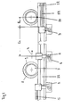
- Fig. 1 of the drawing is a magnetorestrictive wheel diameter measuring device schematically represented by the Distance between the circumferential segments 10 of a roll angle of a rail-bound vehicle wheel 7 measured at 360 ° with the help of the respective in an evaluation device Wheel diameter can be calculated and to determine the Axle or wheel load is used.
- the magnetorestrictive wheel diameter measuring device consists in essentially from a demagnetization 1, a magnetization 2 and a position detection device 3, by which is the length of a given rolling distance of a magnetized one Segment 10 on the circumference of a rail-bound vehicle wheel 7 is detected. This is in the direction 4 of the vehicle wheel in front of the magnetization 2 and the position detection device 3, the demagnetization device 1 is arranged. This is preferably next to the rail head 12 mounted at a distance and contains in a longitudinal housing body 5 shows a coil arrangement which has an alternating magnetic field generated. As soon as the vehicle wheel 7 to be measured as a measurement object rolls past this alternating magnetic field in its ferromagnetic rim 8 or tire 9 residual magnetism present therein is eliminated.
- the Demagnetizing device 1 can also be the whole Wheel diameter are compared and so during the Pass the wheel over a short distance.
- the magnetization device on the next threshold 6 2 attached which has a strong electromagnet contains the one when driving past the vehicle wheel 7 Magnetizing pulse generated.
- this magnetization pulse targeted to a partial segment 10 of the wheel tire 9 directed and magnetized this on a circumferential segment of approx. 5 mm.
- This circumferential segment 10 rolls as it drives past of the vehicle wheel 7 at an angular speed the rail 11 and hits at a roll angle of 360 ° back on the rail head 12. Therefore is at a distance from about 2 to 4 m from the magnetizing device 2 the position detection device 3 is arranged.
- the magnetization 2 and position detection device 3 but can also be provided in a common housing part become.
- This magnetorestrictive position detection device 3 contains a sensor head on which a tubular measuring rod 14 is arranged, which is along a length of about 2m Rail 12 extends and attached to this or the sleepers 6 is.
- the dipstick 14 consists of a magnetorestrictive or ferromagnetic waveguide in a protective tube the dipstick 14 is arranged.
- the waveguide is in the transducer head connected to a transmitting device that has a pulse generator contains a current pulse when activated feeds into the waveguide.
- the transmission device when a vehicle wheel 7 is crossed by a Rail switch activates and sends at regular intervals Storm impulses on the waveguide.
- This receiving device essentially consists of a signal converter, which is arranged above the waveguide, and consists of a permanent magnet, a ferromagnetic metal strip and a detection coil surrounding it.
- the reflected electromagnetic wave causes a change in permeability in the metal strip, which is converted into an electrical signal in the detection coil.
- This electrical response signal or measurement signal takes place in a transit time which is proportional to the distance S 2 or length between the starting point of the position detection device 3 as the first or reference point and the point of impact of the magnetized peripheral segment as the second point of the vehicle wheel as the measurement object.
- a length measurement is basically carried out by the position detection device 3 along the rail 11.
- the signal converter in the receiving device is connected to an electronic evaluation device, which first calculates the rolling path between the end point of the sensor head housing as the reference point of the measurement object and the point of impact of the magnetized wheel segment 10 as the second point of the measurement object 7 from the electrical measurement signal.
- the distance S 1 between the magnetization point as the first point of the measurement object and the end point of the transducer head housing is also entered as a reference point, which is added to the determined measurement distance S 2 and thus corresponds to the detected wheel circumference of a roll angle of 360 °.
- the evaluation device determines the rolling distance of the magnetized wheel circumference segment 10 from a reference point on the wheel circumference 10 or from an intended location of the magnetization device 2 on the rail 11 and a rolling angle of 360 ° when the magnetized wheel circumference segment 10 reappears on the rail 11 as a second point on the measurement object , Since the wheel diameter or the wheel size is required to actually determine the permissible wheel or axle load, the electronic evaluation device calculates a characteristic value for the wheel diameter in millimeters from the wheel circumference.
- the evaluation device From the known time interval during the rollover of the vehicle wheel 7 and the rolling distance are determined by the evaluation device at the same time the overrun speed, which advantageously with maximum permissible crossing speeds can be compared. Out of it are at the same time the center distances of a wagon or vehicle can also be derived, through which the evaluation device also at the same time determined the wagon type. In a preferred embodiment is at the same time when crossing an entire train group also counted the number of axes and with a given one Number compared, from which derailment of individual axles or the loss of one or more wagons and can be signaled. The evaluation device also compares also the determined wheel circumference values at the same time of a vehicle with each other and provides for deviations individual wheels blocking or slipping of the deviating Wheel fixed. From the determined individual wheel diameters can by comparison with predetermined target diameters also the wear or compliance with the permissible tolerance values be monitored.
- the evaluation device can advantageously also be provided Temperature sensors to determine the brake and / or storage temperature can be used. With the exact determination the bearing and brake overheating or their temperature it is necessary to determine the distance between the temperature sensors on the track and the components to be measured know. This can be done based on a type recognition from given Values are derived, but is preferably also with Can be determined using the wheel diameter measuring device. That I the distances between the brake discs or the bearings essentially the distance to the rail results from the wheel diameter 11 or to the fixed temperature sensors on simple Way by the determined wheel diameter minus the parts the bearing diameter or the brake disc diameter calculated and with the corresponding recorded temperature values connected.
- demagnetization device 1 Following the crossing via the position detection device 3 can simultaneously a further demagnetization device 1 are provided, which in residual magnetism the rail 11 and in the vehicle wheel eliminated so that they do not subsequent measurements affect.
- Fig. 2 of the drawing is an optical diameter measuring device schematically shown, arranged transversely to the rail 11 is and the rim 8 in a range of 60 to Scans 130 cm above the top of the rail and with one Evaluation device that is connected from the reference point the upper edge of the rail 11 and the detected upper edge of one passing vehicle wheel 7 the distance between these two Points calculated as wheel diameter.
- This optical diameter measuring device essentially consists from a transmitter that emits light or laser waves on the wheel rim 8 and a receiving device that the light or laser waves reflecting from the wheel rim 8 receives and feeds its signals to an evaluation device.
- the transmitting and receiving device is in one Housing that is at least at a height of 60 to 130 cm vertically above the top edge of the rail and to the side next to the rolling vehicle wheels 7 of a rail-bound vehicle attached spaced is.
- the transmitter device consists of one or more Light sources that cover a range of approx. 60 to 130 cm above the top edge of the rail when driving through of a vehicle wheel illuminated.
- the transmitter can also consist of a predetermined number of spaced laser sources, their distance at least usual wheel size differences must correspond. Because wheel sizes occurring today are preferred 69 cm to 125 cm in diameter must be at least so many laser light sources can be arranged that they illuminate these wheel sizes on their vertical rim.
- the receiving device consists of an optical receiver, the one in the same vertical area next to the transmitter is arranged and a vertical row of photosensitive Has transducer elements which are arranged that they receive the reflecting light or laser beams.
- the sending and receiving devices are in common Evaluation device connected to the transmission device controls and the received reflected light signals evaluates.
- a Rail switch activated the wheel diameter measuring device and the transmission device switched so that a uniform or clocked light beam in a vertical range of at least 60 to 130 cm above the rail edge against the Vehicle wheel 7 is sent.
- These rays of light will especially of the shiny metallic radial rim segments 8 reflected by the rays of light, the radial rim segments 8 having a height of approx. 70 mm.
- the light pulses are preferably so controlled that they are sent out only at one time on which the vehicle wheel 7 with its footprint exactly is located below the transmitter. This ensures that exactly one wheel roll segment of 180 ° in its maximum Extension is scanned.
- the wheel rim 8 Due to the friction of the wheel rim 8 on the inner wall of the rail 11, this acts like a mirror surface and reflects almost only the emitted light waves, which preferably the area of the wheel rim 8 is a segment that is 180 ° opposite the rail surface. These reflected light waves fall on photosensitive elements, in particular photosensitive resistors in the receiving device, and generate electrical signals there which correspond to the vertical intensity distribution of the reflected light waves. From the area of the vertical intensity distribution, a signal results which corresponds to the distance S 2 'between the lower reception point as the reference point and the lower point with the highest intensity distribution as the second point on the measurement object. In the evaluation device, the distance S 2 'from the reference point is calculated from the area with the highest intensity distribution and added with the distance S 1 ' between the top edge of the rail as the first point of the measurement object and the reference point, which gives the respective wheel diameter.
- Such a scanning of the wheel diameter can also be done with others directed electromagnetic waves such as infrared radiation. This works without contact Diameter probes through their vertical Arrangement from a wheel circumference of 180 °, its length equals the diameter. Because the previous wheel sizes only in a stepped area of 69 to 125 cm in diameter vary, is only at this horizontal distance from the The upper edge of the rail each has a transmitting and receiving device provided. The distance levels are also known in this area, so that the measurement signals are only evaluated in this area and compared with the wheel diameters occurring there need to be determined in order to determine an exact diameter.
- Such a diameter scan can also be done with at least two horizontally arranged optical measuring devices be carried out, the wheel rim segments 8 at a distance of 180 ° and from the individual reference values Calculate the difference that corresponds to the diameter of the vehicle wheel 7 corresponds as a measurement object.
- the evaluation device is designed so that the wheel diameter displayed or as an output signal for further processing further computing systems is transmitted. Because the individual Wheel diameter of a rail-bound vehicle wheel The maximum permissible wheel or axle loads can be assigned directly , they can also be displayed directly and by comparison monitored with a correspondingly determined wheel load and the exceeding are signaled.
- Photographic recordings are also required for wheel diameter detection feasible by the passing vehicle wheel, its pixels in an electronic evaluation device by appropriate Programs are evaluated so that the wheel diameter can be determined.
- the further linking of the wheel diameter signals can according to the description of the above Fig. 1 take place.
- the exemplary embodiments described do not limit the scope of protection, but rather give only a limited number of execution options again.
Landscapes
- Engineering & Computer Science (AREA)
- Physics & Mathematics (AREA)
- General Physics & Mathematics (AREA)
- Automation & Control Theory (AREA)
- Mechanical Engineering (AREA)
- Measurement Of Length, Angles, Or The Like Using Electric Or Magnetic Means (AREA)
- Length Measuring Devices With Unspecified Measuring Means (AREA)
- Length Measuring Devices By Optical Means (AREA)
Applications Claiming Priority (2)
| Application Number | Priority Date | Filing Date | Title |
|---|---|---|---|
| DE10305923A DE10305923A1 (de) | 2003-02-13 | 2003-02-13 | Vorrichtung und Verfahren zur Messung des Abstandes zweier Punkte eines Meßobjekts, insbesondere zur Messung des Raddurchmessers eines schienengebundenen Fahrzeugrades |
| DE10305923 | 2003-02-13 |
Publications (3)
| Publication Number | Publication Date |
|---|---|
| EP1447679A2 true EP1447679A2 (fr) | 2004-08-18 |
| EP1447679A3 EP1447679A3 (fr) | 2004-10-06 |
| EP1447679B1 EP1447679B1 (fr) | 2006-09-13 |
Family
ID=32668050
Family Applications (1)
| Application Number | Title | Priority Date | Filing Date |
|---|---|---|---|
| EP04002890A Expired - Lifetime EP1447679B1 (fr) | 2003-02-13 | 2004-02-10 | Dispositif et procédé pour mesurer la distance entre deux points d'un objet, en particulier pour mesurer le diamètre d'une roue d'un véhicule ferroviaire |
Country Status (3)
| Country | Link |
|---|---|
| EP (1) | EP1447679B1 (fr) |
| AT (1) | ATE339697T1 (fr) |
| DE (2) | DE10305923A1 (fr) |
Cited By (3)
| Publication number | Priority date | Publication date | Assignee | Title |
|---|---|---|---|---|
| CN102589454A (zh) * | 2012-02-10 | 2012-07-18 | 南车长江车辆有限公司 | 一种铁路货车车轮旋削方法 |
| CN102607398A (zh) * | 2012-03-06 | 2012-07-25 | 清华大学 | 正交点电接触标准棒的微细电极直径在线测量方法 |
| CN112816040A (zh) * | 2020-12-30 | 2021-05-18 | 贵州中航聚电科技有限公司 | 一种多功能的钽电容测量工装 |
Families Citing this family (3)
| Publication number | Priority date | Publication date | Assignee | Title |
|---|---|---|---|---|
| DE102004047506B4 (de) * | 2004-09-28 | 2007-12-06 | Daimlerchrysler Ag | Verfahren und Vorrichtung zur bildgestützten Kalibrierung von Tachographen bei Fahrzeugen |
| DE102011089464A1 (de) | 2011-12-21 | 2013-06-27 | Technische Universität Berlin | Verfahren und Vorrichtung zur Bestimmung von Raddurchmessern an Schienenfahrzeugen |
| DE202017002469U1 (de) | 2017-05-09 | 2017-06-01 | DB Systemtechnik GmbH | Vorrichtung zur Bestimmung des Durchmessers eines schienengebundenen Fahrzeugrades |
Family Cites Families (14)
| Publication number | Priority date | Publication date | Assignee | Title |
|---|---|---|---|---|
| US3767146A (en) * | 1972-06-22 | 1973-10-23 | Servo Corp Of America | Railway safety system for detecting overheated brakes |
| US4155526A (en) * | 1977-11-09 | 1979-05-22 | Westinghouse Air Brake Company | Railroad car wheel measuring apparatus |
| JPS56148003A (en) * | 1980-04-18 | 1981-11-17 | Universal Kiki Kk | Measuring apparatus for wheel diameter |
| DE3226740C2 (de) * | 1982-07-16 | 1985-12-19 | Meßmetallurgie GmbH, 5810 Witten | Verfahren sowie Vorrichtung zum Bestimmen der Radlasten schnellfahrender Schienenfahrzeuge |
| SU1311980A1 (ru) * | 1985-04-26 | 1987-05-23 | Уральское отделение Всесоюзного научно-исследовательского института железнодорожного транспорта | Путевой индикатор юза колеса |
| DE3522809A1 (de) * | 1985-06-26 | 1987-01-02 | Hegenscheidt Gmbh Wilhelm | Verfahren und messanlage zur durchmesserbestimmung der raeder von radsaetzen |
| EP0212052B1 (fr) * | 1985-08-12 | 1992-10-21 | Wilhelm Hegenscheidt Gesellschaft mbH | Dispositif pour la mesure des roues d'ensembles de roues intégrées dans le véhicule |
| DE3620208A1 (de) * | 1986-06-16 | 1987-12-17 | Siemens Ag | Einrichtung auf einem spurgebundenen fahrzeug |
| DE3721127A1 (de) * | 1987-06-26 | 1989-01-26 | Tiefenbach Gmbh | Radsensor |
| DE29516461U1 (de) * | 1994-12-08 | 1996-01-18 | Hegenscheidt-MFD GmbH & Co. KG, 41812 Erkelenz | Vorrichtung zur Durchmesserbestimmung eines Rades |
| CH688728A5 (de) * | 1995-01-20 | 1998-01-30 | Von Roll Betec Ag | Verfahren und Vorrichtung zum Bestimmen von Raddurchmessern. |
| US5636026A (en) * | 1995-03-16 | 1997-06-03 | International Electronic Machines Corporation | Method and system for contactless measurement of railroad wheel characteristics |
| DE10064598C1 (de) * | 2000-12-18 | 2002-07-18 | Siemens Ag | Verfahren zum Erzeugen eines die Zusammensetzung eines Eisenbahnzuges angebenden Datensatzes |
| DE10114482B4 (de) * | 2001-03-24 | 2008-07-17 | Schenck Process Gmbh | Vorrichtung und Verfahren zur dynamischen Messung der Achslast oder des Gewichts von Schienenfahrzeugen |
-
2003
- 2003-02-13 DE DE10305923A patent/DE10305923A1/de not_active Withdrawn
-
2004
- 2004-02-10 EP EP04002890A patent/EP1447679B1/fr not_active Expired - Lifetime
- 2004-02-10 DE DE502004001436T patent/DE502004001436D1/de not_active Expired - Lifetime
- 2004-02-10 AT AT04002890T patent/ATE339697T1/de not_active IP Right Cessation
Cited By (3)
| Publication number | Priority date | Publication date | Assignee | Title |
|---|---|---|---|---|
| CN102589454A (zh) * | 2012-02-10 | 2012-07-18 | 南车长江车辆有限公司 | 一种铁路货车车轮旋削方法 |
| CN102607398A (zh) * | 2012-03-06 | 2012-07-25 | 清华大学 | 正交点电接触标准棒的微细电极直径在线测量方法 |
| CN112816040A (zh) * | 2020-12-30 | 2021-05-18 | 贵州中航聚电科技有限公司 | 一种多功能的钽电容测量工装 |
Also Published As
| Publication number | Publication date |
|---|---|
| EP1447679A3 (fr) | 2004-10-06 |
| EP1447679B1 (fr) | 2006-09-13 |
| ATE339697T1 (de) | 2006-10-15 |
| DE10305923A1 (de) | 2004-08-26 |
| DE502004001436D1 (de) | 2006-10-26 |
Similar Documents
| Publication | Publication Date | Title |
|---|---|---|
| DE69920916T2 (de) | Verfahren und vorrichtung zur ermittlung defekter eisenbahnräder | |
| EP1952092B1 (fr) | Appareil concu pour controler la profondeur et le type de la sculpture de pneu, la vitesse et la garde au sol sur des vehicules en deplacement | |
| EP0212052B1 (fr) | Dispositif pour la mesure des roues d'ensembles de roues intégrées dans le véhicule | |
| DE102011017134B4 (de) | Anordnung zur Vermessung von Gleisabschnitten zum Zweck der Instandhaltung von Eisenbahnschienen | |
| EP0208060B1 (fr) | Méthode et dispositif pour la détermination de diamètres des roues de paires de roues | |
| EP3186128A1 (fr) | Dispositif et procédé pour la détermination de caractéristiques géométriques d'un profil de roue sur une roue qui tourne d'un véhicule ferroviaire | |
| CH684531A5 (de) | Messanordnung zum kontinuierlichen Messen von wellenförmigen Unebenheiten einer Schiene. | |
| EP1394503B1 (fr) | Dispositif pour mesurer la profondeur d'un profil | |
| DE102016105413A1 (de) | Geschwindigkeitsmessverfahren und geschwindigkeitsmessanordnung | |
| EP1592595B1 (fr) | Parcours de mesure permettant de determiner differentes grandeurs physiques de vehicules ferroviaires | |
| EP2903879A2 (fr) | Localisation de véhicule | |
| EP0618459A2 (fr) | Système pour arrêrer des véhicules sur une position exacte | |
| EP0265538B1 (fr) | Dispositif pour la mesure sans contact des températures des freins de voitures de chemin de fer qui passent | |
| DE19729990B4 (de) | Verfahren und Vorrichtung zur Bestimmung der zurückgelegten Wegstrecke und der Geschwindigkeit von Schienenfahrzeugen | |
| EP1447679A2 (fr) | Dispositif et procédé pour mesurer la distance entre deux points d'un objet, en particulier pour mesurer le diamètre d'une roue d'un véhicule ferroviaire | |
| DE4238151C2 (de) | Verfahren zur Ermittlung der Temperatur von Eisenbahnfahrzeugen und Fahrzeugkomponenten und Vorrichtung zur Durchführung des Verfahrens | |
| DE202015005230U1 (de) | Schienenfahrzeug | |
| EP0891911A1 (fr) | Procédé et dispositif pour déterminer la distance parcourue par un corps | |
| WO2008006803A1 (fr) | Système, en particulier système de trafic ferroviaire à petite distance, et procédé pour la détection du trajet côté véhicule pour un tel système | |
| DE19717662A1 (de) | Verfahren und Einrichtung zur kontinuierlichen Ermittlung der Position eines Schienenfahrzeugs | |
| EP1572517B1 (fr) | Train a grande vitesse avec un systeme d'avertissement d'obstacle | |
| EP3976439B1 (fr) | Dispositif de capteur pour un ensemble de détection et d'analyse d'une roue d'un véhicule déplacée le long d'une voie, en particulier le long d'une voie ferrée | |
| EP2386456B1 (fr) | Procédé et dispositif de vérification de rails au niveau des cannelures | |
| DE3623423A1 (de) | Sensorsystem zum positionieren einer laufkatze oder eines schienengefuehrten krans | |
| DE4234880A1 (de) | Vorrichtung zur Erfassung von Kraftfahrzeugen |
Legal Events
| Date | Code | Title | Description |
|---|---|---|---|
| PUAI | Public reference made under article 153(3) epc to a published international application that has entered the european phase |
Free format text: ORIGINAL CODE: 0009012 |
|
| AK | Designated contracting states |
Kind code of ref document: A2 Designated state(s): AT BE BG CH CY CZ DE DK EE ES FI FR GB GR HU IE IT LI LU MC NL PT RO SE SI SK TR |
|
| AX | Request for extension of the european patent |
Extension state: AL LT LV MK |
|
| PUAL | Search report despatched |
Free format text: ORIGINAL CODE: 0009013 |
|
| AK | Designated contracting states |
Kind code of ref document: A3 Designated state(s): AT BE BG CH CY CZ DE DK EE ES FI FR GB GR HU IE IT LI LU MC NL PT RO SE SI SK TR |
|
| AX | Request for extension of the european patent |
Extension state: AL LT LV MK |
|
| 17P | Request for examination filed |
Effective date: 20050405 |
|
| 17Q | First examination report despatched |
Effective date: 20050510 |
|
| AKX | Designation fees paid |
Designated state(s): AT BE BG CH CY CZ DE DK EE ES FI FR GB GR HU IE IT LI LU MC NL PT RO SE SI SK TR |
|
| GRAP | Despatch of communication of intention to grant a patent |
Free format text: ORIGINAL CODE: EPIDOSNIGR1 |
|
| GRAS | Grant fee paid |
Free format text: ORIGINAL CODE: EPIDOSNIGR3 |
|
| GRAA | (expected) grant |
Free format text: ORIGINAL CODE: 0009210 |
|
| AK | Designated contracting states |
Kind code of ref document: B1 Designated state(s): AT BE BG CH CY CZ DE DK EE ES FI FR GB GR HU IE IT LI LU MC NL PT RO SE SI SK TR |
|
| PG25 | Lapsed in a contracting state [announced via postgrant information from national office to epo] |
Ref country code: IT Free format text: LAPSE BECAUSE OF FAILURE TO SUBMIT A TRANSLATION OF THE DESCRIPTION OR TO PAY THE FEE WITHIN THE PRESCRIBED TIME-LIMIT;WARNING: LAPSES OF ITALIAN PATENTS WITH EFFECTIVE DATE BEFORE 2007 MAY HAVE OCCURRED AT ANY TIME BEFORE 2007. THE CORRECT EFFECTIVE DATE MAY BE DIFFERENT FROM THE ONE RECORDED. Effective date: 20060913 Ref country code: IE Free format text: LAPSE BECAUSE OF FAILURE TO SUBMIT A TRANSLATION OF THE DESCRIPTION OR TO PAY THE FEE WITHIN THE PRESCRIBED TIME-LIMIT Effective date: 20060913 Ref country code: SK Free format text: LAPSE BECAUSE OF FAILURE TO SUBMIT A TRANSLATION OF THE DESCRIPTION OR TO PAY THE FEE WITHIN THE PRESCRIBED TIME-LIMIT Effective date: 20060913 Ref country code: FI Free format text: LAPSE BECAUSE OF FAILURE TO SUBMIT A TRANSLATION OF THE DESCRIPTION OR TO PAY THE FEE WITHIN THE PRESCRIBED TIME-LIMIT Effective date: 20060913 Ref country code: RO Free format text: LAPSE BECAUSE OF FAILURE TO SUBMIT A TRANSLATION OF THE DESCRIPTION OR TO PAY THE FEE WITHIN THE PRESCRIBED TIME-LIMIT Effective date: 20060913 Ref country code: NL Free format text: LAPSE BECAUSE OF FAILURE TO SUBMIT A TRANSLATION OF THE DESCRIPTION OR TO PAY THE FEE WITHIN THE PRESCRIBED TIME-LIMIT Effective date: 20060913 Ref country code: GB Free format text: LAPSE BECAUSE OF FAILURE TO SUBMIT A TRANSLATION OF THE DESCRIPTION OR TO PAY THE FEE WITHIN THE PRESCRIBED TIME-LIMIT Effective date: 20060913 Ref country code: SI Free format text: LAPSE BECAUSE OF FAILURE TO SUBMIT A TRANSLATION OF THE DESCRIPTION OR TO PAY THE FEE WITHIN THE PRESCRIBED TIME-LIMIT Effective date: 20060913 Ref country code: CZ Free format text: LAPSE BECAUSE OF FAILURE TO SUBMIT A TRANSLATION OF THE DESCRIPTION OR TO PAY THE FEE WITHIN THE PRESCRIBED TIME-LIMIT Effective date: 20060913 |
|
| REG | Reference to a national code |
Ref country code: GB Ref legal event code: FG4D Free format text: NOT ENGLISH |
|
| REG | Reference to a national code |
Ref country code: CH Ref legal event code: EP |
|
| REG | Reference to a national code |
Ref country code: IE Ref legal event code: FG4D Free format text: LANGUAGE OF EP DOCUMENT: GERMAN |
|
| REF | Corresponds to: |
Ref document number: 502004001436 Country of ref document: DE Date of ref document: 20061026 Kind code of ref document: P |
|
| PG25 | Lapsed in a contracting state [announced via postgrant information from national office to epo] |
Ref country code: SE Free format text: LAPSE BECAUSE OF FAILURE TO SUBMIT A TRANSLATION OF THE DESCRIPTION OR TO PAY THE FEE WITHIN THE PRESCRIBED TIME-LIMIT Effective date: 20061213 Ref country code: BG Free format text: LAPSE BECAUSE OF FAILURE TO SUBMIT A TRANSLATION OF THE DESCRIPTION OR TO PAY THE FEE WITHIN THE PRESCRIBED TIME-LIMIT Effective date: 20061213 Ref country code: DK Free format text: LAPSE BECAUSE OF FAILURE TO SUBMIT A TRANSLATION OF THE DESCRIPTION OR TO PAY THE FEE WITHIN THE PRESCRIBED TIME-LIMIT Effective date: 20061213 |
|
| PG25 | Lapsed in a contracting state [announced via postgrant information from national office to epo] |
Ref country code: ES Free format text: LAPSE BECAUSE OF FAILURE TO SUBMIT A TRANSLATION OF THE DESCRIPTION OR TO PAY THE FEE WITHIN THE PRESCRIBED TIME-LIMIT Effective date: 20061224 |
|
| PG25 | Lapsed in a contracting state [announced via postgrant information from national office to epo] |
Ref country code: PT Free format text: LAPSE BECAUSE OF FAILURE TO SUBMIT A TRANSLATION OF THE DESCRIPTION OR TO PAY THE FEE WITHIN THE PRESCRIBED TIME-LIMIT Effective date: 20070226 |
|
| PG25 | Lapsed in a contracting state [announced via postgrant information from national office to epo] |
Ref country code: MC Free format text: LAPSE BECAUSE OF NON-PAYMENT OF DUE FEES Effective date: 20070228 |
|
| NLV1 | Nl: lapsed or annulled due to failure to fulfill the requirements of art. 29p and 29m of the patents act | ||
| GBV | Gb: ep patent (uk) treated as always having been void in accordance with gb section 77(7)/1977 [no translation filed] |
Effective date: 20060913 |
|
| REG | Reference to a national code |
Ref country code: IE Ref legal event code: FD4D |
|
| EN | Fr: translation not filed | ||
| PLBE | No opposition filed within time limit |
Free format text: ORIGINAL CODE: 0009261 |
|
| STAA | Information on the status of an ep patent application or granted ep patent |
Free format text: STATUS: NO OPPOSITION FILED WITHIN TIME LIMIT |
|
| 26N | No opposition filed |
Effective date: 20070614 |
|
| BERE | Be: lapsed |
Owner name: SCHENCK PROCESS G.M.B.H. Effective date: 20070228 |
|
| PG25 | Lapsed in a contracting state [announced via postgrant information from national office to epo] |
Ref country code: BE Free format text: LAPSE BECAUSE OF NON-PAYMENT OF DUE FEES Effective date: 20070228 |
|
| PG25 | Lapsed in a contracting state [announced via postgrant information from national office to epo] |
Ref country code: FR Free format text: LAPSE BECAUSE OF FAILURE TO SUBMIT A TRANSLATION OF THE DESCRIPTION OR TO PAY THE FEE WITHIN THE PRESCRIBED TIME-LIMIT Effective date: 20070518 Ref country code: GR Free format text: LAPSE BECAUSE OF FAILURE TO SUBMIT A TRANSLATION OF THE DESCRIPTION OR TO PAY THE FEE WITHIN THE PRESCRIBED TIME-LIMIT Effective date: 20061214 |
|
| PG25 | Lapsed in a contracting state [announced via postgrant information from national office to epo] |
Ref country code: AT Free format text: LAPSE BECAUSE OF NON-PAYMENT OF DUE FEES Effective date: 20070210 |
|
| PG25 | Lapsed in a contracting state [announced via postgrant information from national office to epo] |
Ref country code: EE Free format text: LAPSE BECAUSE OF FAILURE TO SUBMIT A TRANSLATION OF THE DESCRIPTION OR TO PAY THE FEE WITHIN THE PRESCRIBED TIME-LIMIT Effective date: 20060913 |
|
| REG | Reference to a national code |
Ref country code: CH Ref legal event code: PL |
|
| PG25 | Lapsed in a contracting state [announced via postgrant information from national office to epo] |
Ref country code: LI Free format text: LAPSE BECAUSE OF NON-PAYMENT OF DUE FEES Effective date: 20080229 Ref country code: CH Free format text: LAPSE BECAUSE OF NON-PAYMENT OF DUE FEES Effective date: 20080229 |
|
| PG25 | Lapsed in a contracting state [announced via postgrant information from national office to epo] |
Ref country code: FR Free format text: LAPSE BECAUSE OF FAILURE TO SUBMIT A TRANSLATION OF THE DESCRIPTION OR TO PAY THE FEE WITHIN THE PRESCRIBED TIME-LIMIT Effective date: 20060913 |
|
| PG25 | Lapsed in a contracting state [announced via postgrant information from national office to epo] |
Ref country code: LU Free format text: LAPSE BECAUSE OF NON-PAYMENT OF DUE FEES Effective date: 20070210 Ref country code: CY Free format text: LAPSE BECAUSE OF FAILURE TO SUBMIT A TRANSLATION OF THE DESCRIPTION OR TO PAY THE FEE WITHIN THE PRESCRIBED TIME-LIMIT Effective date: 20060913 |
|
| PG25 | Lapsed in a contracting state [announced via postgrant information from national office to epo] |
Ref country code: TR Free format text: LAPSE BECAUSE OF FAILURE TO SUBMIT A TRANSLATION OF THE DESCRIPTION OR TO PAY THE FEE WITHIN THE PRESCRIBED TIME-LIMIT Effective date: 20060913 Ref country code: HU Free format text: LAPSE BECAUSE OF FAILURE TO SUBMIT A TRANSLATION OF THE DESCRIPTION OR TO PAY THE FEE WITHIN THE PRESCRIBED TIME-LIMIT Effective date: 20070314 |
|
| PGFP | Annual fee paid to national office [announced via postgrant information from national office to epo] |
Ref country code: DE Payment date: 20130219 Year of fee payment: 10 |
|
| REG | Reference to a national code |
Ref country code: DE Ref legal event code: R119 Ref document number: 502004001436 Country of ref document: DE |
|
| REG | Reference to a national code |
Ref country code: DE Ref legal event code: R119 Ref document number: 502004001436 Country of ref document: DE Effective date: 20140902 |
|
| PG25 | Lapsed in a contracting state [announced via postgrant information from national office to epo] |
Ref country code: DE Free format text: LAPSE BECAUSE OF NON-PAYMENT OF DUE FEES Effective date: 20140902 |