EP1447881A2 - Système de connexion pour des câbles coaxiales et procédé de montage - Google Patents
Système de connexion pour des câbles coaxiales et procédé de montage Download PDFInfo
- Publication number
- EP1447881A2 EP1447881A2 EP04000665A EP04000665A EP1447881A2 EP 1447881 A2 EP1447881 A2 EP 1447881A2 EP 04000665 A EP04000665 A EP 04000665A EP 04000665 A EP04000665 A EP 04000665A EP 1447881 A2 EP1447881 A2 EP 1447881A2
- Authority
- EP
- European Patent Office
- Prior art keywords
- connector
- cable
- outer conductor
- section
- internal
- Prior art date
- Legal status (The legal status is an assumption and is not a legal conclusion. Google has not performed a legal analysis and makes no representation as to the accuracy of the status listed.)
- Withdrawn
Links
- 238000000034 method Methods 0.000 title description 3
- 239000004020 conductor Substances 0.000 claims abstract description 143
- 238000002788 crimping Methods 0.000 claims abstract description 24
- 239000006260 foam Substances 0.000 claims abstract description 24
- 229910052782 aluminium Inorganic materials 0.000 claims abstract description 19
- XAGFODPZIPBFFR-UHFFFAOYSA-N aluminium Chemical compound [Al] XAGFODPZIPBFFR-UHFFFAOYSA-N 0.000 claims abstract description 19
- 229910000838 Al alloy Inorganic materials 0.000 claims abstract description 12
- 230000009977 dual effect Effects 0.000 claims description 74
- 230000013011 mating Effects 0.000 claims description 18
- 239000000463 material Substances 0.000 claims description 9
- XLYOFNOQVPJJNP-UHFFFAOYSA-N water Substances O XLYOFNOQVPJJNP-UHFFFAOYSA-N 0.000 claims description 6
- 238000003780 insertion Methods 0.000 claims description 4
- 230000037431 insertion Effects 0.000 claims description 4
- 229910000906 Bronze Inorganic materials 0.000 claims description 3
- 230000015572 biosynthetic process Effects 0.000 claims description 3
- 239000010974 bronze Substances 0.000 claims description 3
- KUNSUQLRTQLHQQ-UHFFFAOYSA-N copper tin Chemical compound [Cu].[Sn] KUNSUQLRTQLHQQ-UHFFFAOYSA-N 0.000 claims description 3
- 238000013508 migration Methods 0.000 claims description 3
- 230000005012 migration Effects 0.000 claims description 3
- 229910001369 Brass Inorganic materials 0.000 claims description 2
- OAICVXFJPJFONN-UHFFFAOYSA-N Phosphorus Chemical compound [P] OAICVXFJPJFONN-UHFFFAOYSA-N 0.000 claims description 2
- 230000001154 acute effect Effects 0.000 claims description 2
- DMFGNRRURHSENX-UHFFFAOYSA-N beryllium copper Chemical compound [Be].[Cu] DMFGNRRURHSENX-UHFFFAOYSA-N 0.000 claims description 2
- 239000010951 brass Substances 0.000 claims description 2
- 239000012530 fluid Substances 0.000 claims description 2
- 230000014759 maintenance of location Effects 0.000 claims description 2
- 230000000149 penetrating effect Effects 0.000 claims 5
- 239000000956 alloy Substances 0.000 claims 4
- 229920002943 EPDM rubber Polymers 0.000 claims 1
- 230000007423 decrease Effects 0.000 claims 1
- 150000002825 nitriles Chemical class 0.000 claims 1
- 229920001084 poly(chloroprene) Polymers 0.000 claims 1
- 229920001296 polysiloxane Polymers 0.000 claims 1
- 230000006835 compression Effects 0.000 description 10
- 238000007906 compression Methods 0.000 description 10
- 238000009434 installation Methods 0.000 description 10
- 230000008595 infiltration Effects 0.000 description 8
- 238000001764 infiltration Methods 0.000 description 8
- 239000012212 insulator Substances 0.000 description 8
- 238000004519 manufacturing process Methods 0.000 description 8
- 230000036961 partial effect Effects 0.000 description 7
- 229910052751 metal Inorganic materials 0.000 description 4
- 239000002184 metal Substances 0.000 description 4
- 229910000679 solder Inorganic materials 0.000 description 4
- 239000000853 adhesive Substances 0.000 description 3
- 230000001070 adhesive effect Effects 0.000 description 3
- 238000007747 plating Methods 0.000 description 3
- 238000006243 chemical reaction Methods 0.000 description 2
- 238000010276 construction Methods 0.000 description 2
- 230000007797 corrosion Effects 0.000 description 2
- 238000005260 corrosion Methods 0.000 description 2
- 239000011888 foil Substances 0.000 description 2
- 230000009545 invasion Effects 0.000 description 2
- 229910001092 metal group alloy Inorganic materials 0.000 description 2
- 238000012986 modification Methods 0.000 description 2
- 230000004048 modification Effects 0.000 description 2
- 238000002360 preparation method Methods 0.000 description 2
- 230000002829 reductive effect Effects 0.000 description 2
- 238000000926 separation method Methods 0.000 description 2
- 238000005476 soldering Methods 0.000 description 2
- VYZAMTAEIAYCRO-UHFFFAOYSA-N Chromium Chemical compound [Cr] VYZAMTAEIAYCRO-UHFFFAOYSA-N 0.000 description 1
- RYGMFSIKBFXOCR-UHFFFAOYSA-N Copper Chemical compound [Cu] RYGMFSIKBFXOCR-UHFFFAOYSA-N 0.000 description 1
- 229910000881 Cu alloy Inorganic materials 0.000 description 1
- BQCADISMDOOEFD-UHFFFAOYSA-N Silver Chemical compound [Ag] BQCADISMDOOEFD-UHFFFAOYSA-N 0.000 description 1
- ATJFFYVFTNAWJD-UHFFFAOYSA-N Tin Chemical compound [Sn] ATJFFYVFTNAWJD-UHFFFAOYSA-N 0.000 description 1
- 238000013459 approach Methods 0.000 description 1
- 230000004323 axial length Effects 0.000 description 1
- 230000000903 blocking effect Effects 0.000 description 1
- 238000005266 casting Methods 0.000 description 1
- 230000015556 catabolic process Effects 0.000 description 1
- 229910052804 chromium Inorganic materials 0.000 description 1
- 239000011651 chromium Substances 0.000 description 1
- 229910052802 copper Inorganic materials 0.000 description 1
- 239000010949 copper Substances 0.000 description 1
- 230000003247 decreasing effect Effects 0.000 description 1
- 230000007812 deficiency Effects 0.000 description 1
- 238000006731 degradation reaction Methods 0.000 description 1
- 230000000694 effects Effects 0.000 description 1
- 230000007613 environmental effect Effects 0.000 description 1
- PCHJSUWPFVWCPO-UHFFFAOYSA-N gold Chemical compound [Au] PCHJSUWPFVWCPO-UHFFFAOYSA-N 0.000 description 1
- 229910052737 gold Inorganic materials 0.000 description 1
- 239000010931 gold Substances 0.000 description 1
- 230000002401 inhibitory effect Effects 0.000 description 1
- 238000003754 machining Methods 0.000 description 1
- 230000008450 motivation Effects 0.000 description 1
- 230000001902 propagating effect Effects 0.000 description 1
- 230000000717 retained effect Effects 0.000 description 1
- 239000000565 sealant Substances 0.000 description 1
- 238000007789 sealing Methods 0.000 description 1
- 229910052709 silver Inorganic materials 0.000 description 1
- 239000004332 silver Substances 0.000 description 1
- 239000007787 solid Substances 0.000 description 1
- 230000001629 suppression Effects 0.000 description 1
- 238000004381 surface treatment Methods 0.000 description 1
- 238000012549 training Methods 0.000 description 1
Images

Classifications
-
- H—ELECTRICITY
- H01—ELECTRIC ELEMENTS
- H01R—ELECTRICALLY-CONDUCTIVE CONNECTIONS; STRUCTURAL ASSOCIATIONS OF A PLURALITY OF MUTUALLY-INSULATED ELECTRICAL CONNECTING ELEMENTS; COUPLING DEVICES; CURRENT COLLECTORS
- H01R13/00—Details of coupling devices of the kinds covered by groups H01R12/70 or H01R24/00 - H01R33/00
- H01R13/46—Bases; Cases
- H01R13/52—Dustproof, splashproof, drip-proof, waterproof, or flameproof cases
- H01R13/5205—Sealing means between cable and housing, e.g. grommet
-
- H—ELECTRICITY
- H01—ELECTRIC ELEMENTS
- H01R—ELECTRICALLY-CONDUCTIVE CONNECTIONS; STRUCTURAL ASSOCIATIONS OF A PLURALITY OF MUTUALLY-INSULATED ELECTRICAL CONNECTING ELEMENTS; COUPLING DEVICES; CURRENT COLLECTORS
- H01R9/00—Structural associations of a plurality of mutually-insulated electrical connecting elements, e.g. terminal strips or terminal blocks; Terminals or binding posts mounted upon a base or in a case; Bases therefor
- H01R9/03—Connectors arranged to contact a plurality of the conductors of a multiconductor cable, e.g. tapping connections
- H01R9/05—Connectors arranged to contact a plurality of the conductors of a multiconductor cable, e.g. tapping connections for coaxial cables
- H01R9/0518—Connection to outer conductor by crimping or by crimping ferrule
-
- H—ELECTRICITY
- H01—ELECTRIC ELEMENTS
- H01R—ELECTRICALLY-CONDUCTIVE CONNECTIONS; STRUCTURAL ASSOCIATIONS OF A PLURALITY OF MUTUALLY-INSULATED ELECTRICAL CONNECTING ELEMENTS; COUPLING DEVICES; CURRENT COLLECTORS
- H01R2103/00—Two poles
-
- H—ELECTRICITY
- H01—ELECTRIC ELEMENTS
- H01R—ELECTRICALLY-CONDUCTIVE CONNECTIONS; STRUCTURAL ASSOCIATIONS OF A PLURALITY OF MUTUALLY-INSULATED ELECTRICAL CONNECTING ELEMENTS; COUPLING DEVICES; CURRENT COLLECTORS
- H01R24/00—Two-part coupling devices, or either of their cooperating parts, characterised by their overall structure
- H01R24/38—Two-part coupling devices, or either of their cooperating parts, characterised by their overall structure having concentrically or coaxially arranged contacts
- H01R24/40—Two-part coupling devices, or either of their cooperating parts, characterised by their overall structure having concentrically or coaxially arranged contacts specially adapted for high frequency
- H01R24/56—Two-part coupling devices, or either of their cooperating parts, characterised by their overall structure having concentrically or coaxially arranged contacts specially adapted for high frequency specially adapted to a specific shape of cables, e.g. corrugated cables, twisted pair cables, cables with two screens or hollow cables
- H01R24/564—Corrugated cables
Definitions
- One aspect of the present invention is to provide a connector for such a cable which complements the cable by offering low cost of manufacture, excellent electrical performance and moisture blockage, secure cable retention, and superior ease and speed of field installation.
- the unique dual lead helical corrugations and aluminum construction of the cable outer conductor presents first-ever challenges to the connector designer.
- the dual helical corrugation creates two separate and independent helical grooves which must each be sealed to prevent moisture migration.
- the use of aluminum as the material for the outer conductor being much softer and more ductile than conventional copper and copper alloys, has to be treated differently in designing a crimp type connector to prevent over deformation of the outer conductor which could degrade electrical performance of the cable.
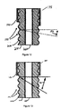
- a single lead coaxial cable 1 75 is depicted in Figure 12.
- the single lead coaxial cable 175 of Figure 12 has an inner conductor 220, a dielectric foam insulator 210 that surrounds the inner conductor 220, and an outer conductor 200 surrounding the foam insulator dielectric 21 0.
- the outer conductor 200 has single lead corrugations 195 which compress the foam insulator dielectric 210.
- the single lead coaxial cable 175 may also have a jacket 190 that surrounds the outer conductor 200.
- the angle 196 is the pitch angle of the outer conductor 200 corrugations.
- a dual lead coaxial cable 180 of the type preferred for use in the system of the present invention is depicted in Figure 13.
- the dual lead coaxial cable 180 of Figure 1 3 also has an inner conductor 220, a foam insulator dielectric 210 that surrounds the inner conductor 220, and an outer conductor 200 surrounding the dielectric 210.
- the outer conductor 200 may be a thin strip of ductile material with a longitudinal high frequency weld seam.
- the outer conductor 200 has dual lead corrugations 197 which tightly compress the dielectric 210. The compression of the dielectric 210 substantially eliminates the formation of fluid propagating air gaps and passageways between the outer conductor 200 and the dielectric 210.
- the dual lead coaxial cable 180 may also have a jacket 190 that surrounds the outer conductor 200.
- the angle 198 is the pitch angle of the outer conductor dual lead corrugations 197 which is twice the pitch angle of a single lead helical corrugation 196.
- Braided cable suffers from electrical and water blockage performance which is inferior to the low cost corrugated cable described.
- braided cable connectors are much more difficult to attach to the cable, requiring elaborate cable preparation in some cases. They are more expensive to manufacture than the present connector as they all require that the connector body provide an inner ferrule against the electrically conductive braid or foil is compressed to retain the connector on the cable.
- Means for moisture-blocking the connector may be integrated into or separate from the means for compressively securing the connector on the cable.
- the connector of the present system offers a relatively simple and low cost approach to securely installing the connector on the cable and preventing moisture invasion into the connector and attached cable.
- the connector of the present invention does not require an inner ferrule against which a braid or foil is compressed to hold the connector on the cable.
- internal helical grooves formed in the hollow inner connector body of the connector enable the connector to be simply screwed onto mating corrugations of the cable outer conductor until the connector reaches a stop.
- the connector body is crimped down on the corrugated outer conductor. This prevents the cable from rotating while in use or during assembly, solidly locking the connector permanently onto the cable.
- the internal bore of the connector body which receives the corrugated cable body may be ribbed longitudinally or circumferentially, roughened or otherwise perturbed in other ways such that when the connector body is crimped down on the outer conductor of the cable, it cannot unscrew or otherwise back out.
- the connector body is provided with radial external ribs which reduce and control the amount of force required to deform the connector body.
- the crimping of the connector body is accomplished with a conventional crimping tool having a hexagonal clamp opening.
- the ribs may be varied in length and/or width to define a deformation profile on the connected cable which permanently secures the cable in the connector, but also optimizes electrical performance and moisture blockage.
- the connector component of the system will now be described in detail. It should be understood that while the connector is most advantageously used with the described low-cost cable having a dual lead helically corrugated aluminum outer conductor, the connector may be employed also with other corrugated cables.
- Connectors for corrugated outer conductor cable are used throughout the semi-flexible corrugated coaxial cable industry.
- connectors have been designed to attach to coaxial cable using solder, and or mechanical compression.
- the quality of a solder connection may vary with the training and motivation of the installation personnel.
- Solder connections are time consuming and require specialized tools, especially during connector installation under field conditions.
- Mechanical compression connections may require compressive force levels that are excessive for field installation, and or special tooling that may not be portable or commercially practical for field installation use.
- Mechanical compression designs using wedging members compressed by tightening threads formed on the connector may be prohibitively expensive to manufacture.
- the corrugation grooves of helically corrugated coaxial cable may provide a moisture infiltration path(s) into the internal areas of the connector and cable interconnection.
- the infiltration path(s) may increase the chances for moisture degradation and or damage to the connector, cable, and or the connector and cable interconnection.
- O-rings or lip seals between the connector and the cable outer conductor and or jacket have been used to minimize moisture infiltration. O-rings may not fully seat/seal into the bottom of the corrugations and lip seals or O-rings sealing against the jacket may fail over time if the jacket material deforms.
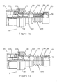
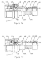
- Figure 1 a shows an external side and partial section view of an embodiment of the invention having an internal crimp area helical grooved section.
- Figure 1 b shows an external side and partial section view of an embodiment of the invention having varied height crimp area ridges.
- Figure 1 c shows an external side and partial section view of an embodiment of the invention having internal crimp area axial grooves.
- Figure 1 d shows an external side and partial section view of an embodiment of the invention having internal crimp area radial grooves.
- Figure 1 e shows an external side and partial section view of an embodiment of the invention having internal crimp area radial ridges.
- Figure 1 f shows an external side and partial section view of an embodiment of the invention having internal crimp area perturbations.
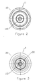
- Figure 3 shows an external cable end view of the embodiment of the invention shown in figure 1.
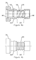
- Figure 4a shows a section side view of a body portion of the embodiment of the invention shown in figure 1.
- Figure 4b shows an external side view of a body portion of the embodiment of the invention shown in figure 1.
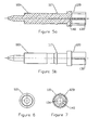
- Figure 5a shows a side section view of an inner contact of the embodiment of the invention shown in figure 1.
- Figure 5b shows an external side view of an inner contact of the embodiment of the invention shown in figure 1.
- Figure 6 shows an external connector end view of the inner contact shown in figures 5a and 5b.
- Figure 7 shows an external cable end view of the inner contact shown in figures 5a and 5b.
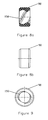
- Figure 8a shows a cross section view of a gasket of the embodiment of the invention shown in figure 1.
- Figure 8b shows an external side-view of a gasket of the embodiment of the invention shown in figure 1.
- Figure 9 shows an external cable end view of the gasket shown in figures 8a and 8b.
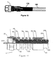
- Figure 10 shows an external side view of a connector according to one embodiment of the invention attached to a cable with heat shrink tubing applied to cover the interface between the cable and the connector.
- Figure 11 shows an external side and partial section view of an embodiment of the invention dimensioned for a type or CATV type connector, also showing a cable within the connector.
- FIG. 1 a One embodiment of a crimp connector, for example a type N connector, is shown in figure 1 a.
- the crimp connector 1 has a connector end 10 (figure 2) and a cable end 20 (figure 3).
- the specific form or connector interface of connector end 10 may depend on the coaxial cable diameter and or the application the crimp connector and selected coaxial cable is intended for.
- the connector end 10 of the crimp connector may be configured with connectors selected to mate with any type of connector mounted on a device or other cable using, for example, standard type F, N, BNC, SMA, DIN, UHF, CATV, EIA, or a proprietary connector configuration.
- Dimensions and or configuration of the crimp connector 1 at the connector end 10 that form the desired standardized connector type are known in the art.
- a connector end 10 in a type N configuration is shown in figures 1 a-1 e, 2 and 3.
- a type F and or CATV connector configuration is shown in figure 11.
- a body 30 forms the outer shell of the cable end 20.
- the body 30 may have a connector end annular shoulder 40 for receiving and retaining via, for example an interference fit, the connector end 10.
- the annular shoulder 40 may be formed as a radial groove into which the connector end 10 may be rotatably attached by, for example, metal stamping or swaging.
- a helical groove section 50 of the embodiments shown in figures 1a, 1b, 4a and 11 preferably mates with exterior configurations and dimensions of a dual lead helical corrugated outer conductor 200 of a dual lead coaxial cable 180 as described in United States utility patent application number 10/131,747 filed April 24, 2002.
- the helical grooves may be formed from continuous. threadlike, grooves or helical shaped rows of axially spaced bumps or other form of appropriately sized and spaced internal perturbations (figure If).
- the dual lead coaxial cable 180 may be dimensioned for various applications with, for example, 50 or 75 ohm impedance.
- the dual lead helical corrugation provides the dual lead coaxial cable 180 with advantageous strength, flexibility and weight characteristics.
- dual grooves that form the dual lead helical corrugation also increase the opportunity for moisture infiltration due to the presence of an additional groove, compared to a traditional single lead helical corrugation, as shown in figure 12.
- the helical groove section 50 increases the contact surface area between the cable outer conductor 200 and the body 30 in the crimp area 100, thereby improving the electrical characteristics of the connection between the body 30 and the outer conductor 200. Also, during installation, the connector 1 is initially threadably retained upon the dual lead coaxial cable 180.
- helical groove section 50 is preferred for optimizing electrical interconnection, accurately forming the helical groove profile of the helical groove section 50 may require advanced machining equipment and or casting methods that may make the body 30 comparatively expensive for some applications and or connector types.
- Examples of simplified alternative mating section structures are shown in figures 1 c-1 e.
- a plurality of axial grooves 52 may be dimensioned to create an interference fit with the outer conductor 200 of the dual lead coaxial cable 180.
- radial grooves 54 may be used.
- Figure 1e demonstrates an embodiment using a plurality of radial ridge(s) 56 where the dual lead coaxial cable 180 may be easily inserted against sloping faces of the radial ridge(s) 56 in the insertion direction towards the connector end 10 but backfaces generally tangential to the axial length of the connector 1 inhibit easy removal. Also, upon compression and or deformation (crimping) of the compression area 100, each of the alternative structures may be expected to securely grasp the outer conductor 200, increasing the reliability of the electrical connection between the dual lead coaxial cable 180 and the connector 1 and also inhibiting separation.
- the body 30 may be formed from, for example brass or other metal alloy. To minimize corrosion and or dissimilar metal reactions with the connector end 10 and or the outer conductor 200 of the dual lead coaxial cable 180, the body 30 may have a corrosion resistant plating, for example, tin or chromium plating.
- a cable end shoulder 80 may be added to the body 30 for seating a gasket 90 or an application of sealant, described herein below.
- a dual lead coaxial cable 180 may be prepared for attaching the crimp connector 1 by exposing an appropriate length of the cable's inner conductor 220 and by removing any outer jacket 190 from a section of the outer conductor 200.
- a gasket 90 may be screwed upon the outer conductor 200 and the crimp connector 1 may then be hand threaded onto the dual lead coaxial cable 180 until the cable's outer conductor 200 impacts upon a stop 60 that extends radially inward across the radial depth of the body 30. When the leading edge of the cable outer conductor 200 contacts the stop 60, further threading may partially collapse/compress the cable outer conductor corrugations into a deformation groove 70.
- the connector 1 is then electrically interconnected and physically secured upon the dual lead cable 180, without requiring field application of solder or conductive adhesive, by applying a crimp in the crimp area 100 sufficient to deform the internal helically grooved section 50 to a point where the dual lead cable 180 may not be unthreaded.
- the connector 1 may be pressed and or screwed upon the similarly prepared dual lead coaxial cable 180, in an interference fit into the mating section, until the outer conductor 200 impacts the stop 60.
- the alternatives may not produce the same resistance to separation once the connector 1 is crimped upon the dual lead coaxial cable 180, because the interlocking effect of the mating between the internal surface of the crimp area 100 and the, for example, dual lead corrugations 197 in the outer conductor 200 is reduced.
- the spacing between the outer conductor 200 and the inner conductor 220 may be decreased to a point where the electrical characteristics of the dual lead coaxial cable 180 are degraded.
- the outer diameter of the crimp area 100 may be adjusted to mate with, for example, industry standard hexagonal crimp hand tools by adjusting the radius and or width of the crimp area 100.
- a plurality of ridges 105 may be formed in the crimp area 100.
- the depth and width of grooves between the ridges 105 may be selected to adjust the compressive force required to compress and or deform the, for example, internal helical groove section 50 and outer conductor 200 of the dual lead coaxial cable 180 during the crimp operation and also to create a corresponding retentive strength of the compressed material once crimped.
- the ridges 105 may be formed with varied heights for example to form a barrel shaped profile with a middle peak. As shown in figure 1b, ridges 105 having a lower depth at either end of the crimp area 100 and an increased height generally in the middle of the crimp area 100 may be formed to both tune the necessary compressive force and or to create a compression/deformation pattern of varied width and depth, once compression is applied over the crimp area 100.
- the inner conductor 220 is inserted into an inner contact 110 (figures 5a-7).
- the inner contact 110 extends between the connector end 10 (figure 6) and the cable end 20 (figure 7).
- An insulator 115 may be mounted in the connector end 10 to locate the inner contact 110 coaxially spaced away from the body 30.
- a radial barb 117 or other structure on the inner contact 110 may be used to retain the inner contact 110 within the insulator 115.
- a socket contact section 120 on the cable end 20 of the inner contact 110 may be formed with a cable end 20 diameter smaller than an outer diameter of the inner conductor 220.
- a plurality of slits 130 may be formed in the socket contact section 120 to allow the socket contact section 120 to easily flex and accommodate the inner conductor 220 upon insertion, creating a secure electrical connection without requiring, for example, soldering or conductive adhesive.
- the inner contact 110 may be formed from a spring temper material, for example beryllium copper, phosphor bronze or other metal or metal alloy with suitable spring/flex characteristics.
- the inner contact 110 may be given a low contact resistance surface treatment, for example, gold or silver plating to increase conductive characteristics and negate dissimilar metal reactions with the center conductor of the dual lead coaxial cable and or other connectors.
- the appropriate length of exposed inner conductor 220 may be a length that results in the inner conductor 220 being inserted into the socket contact section 120 short of contacting a depression 140 when the outer conductor 200 of the dual lead coaxial cable 180 has fully seated against the stop 60 and any compression of the outer conductor 200 into the deformation groove 70 is completed.
- the inner contact 110 is not required.
- the dual lead coaxial cable 180 is prepared with a portion of the inner conductor 220 exposed so that it will extend through the body 30 to the connector end 10 when the dual lead coaxial cable 180 is mated with the connector 1.
- heat shrink tubing 170 may be applied over the body 30 and dual lead coaxial cable 180 interface as an additional environmental seal and to improve rigidity of the connection between the crimp connector 1 and the dual lead coaxial cable 180.
- the extended section of heat shrink tubing 170 covering the dual lead coaxial cable 180 creates an extended path through which moisture must pass to infiltrate the interconnection between the body 30 and the dual lead coaxial cable 180.
- the section of heat shrink tubing 170 over the body 30 is relatively short, creating an increased opportunity for moisture infiltration.
- an outward facing radial body barb 160 may be formed on the body 30. When the heat shrink tubing 170 is shrunk into place upon the body 30, the body barb 160 presents an acute contact surface that the heat shrink tubing 170 will tightly seal against and or around thereby reducing the opportunity for moisture infiltration and increasing the overall rigidity of the assembly.
Landscapes
- Coupling Device And Connection With Printed Circuit (AREA)
Applications Claiming Priority (4)
| Application Number | Priority Date | Filing Date | Title |
|---|---|---|---|
| US249112 | 1994-05-25 | ||
| US10/248,741 US6840803B2 (en) | 2003-02-13 | 2003-02-13 | Crimp connector for corrugated cable |
| US248741 | 2003-02-13 | ||
| US10/249,112 US6848941B2 (en) | 2003-02-13 | 2003-03-17 | Low cost, high performance cable-connector system and assembly method |
Publications (2)
| Publication Number | Publication Date |
|---|---|
| EP1447881A2 true EP1447881A2 (fr) | 2004-08-18 |
| EP1447881A3 EP1447881A3 (fr) | 2009-07-29 |
Family
ID=32684621
Family Applications (1)
| Application Number | Title | Priority Date | Filing Date |
|---|---|---|---|
| EP04000665A Withdrawn EP1447881A3 (fr) | 2003-02-13 | 2004-01-15 | Système de connexion pour des câbles coaxiales et procédé de montage |
Country Status (3)
| Country | Link |
|---|---|
| US (1) | US6848941B2 (fr) |
| EP (1) | EP1447881A3 (fr) |
| CN (1) | CN100399630C (fr) |
Cited By (4)
| Publication number | Priority date | Publication date | Assignee | Title |
|---|---|---|---|---|
| EP2184814A1 (fr) * | 2008-11-05 | 2010-05-12 | Andrew LLC | Connecteur à compression axiale |
| DE102010035484B3 (de) * | 2010-08-26 | 2011-12-01 | Kathrein-Werke Kg | Außenleiter-Kontaktelement für koaxiale Kabelenden |
| WO2013058408A3 (fr) * | 2011-10-18 | 2013-08-01 | Yazaki Corporation | Chemin conducteur |
| CN115799928A (zh) * | 2018-03-14 | 2023-03-14 | 康普技术有限责任公司 | 同轴偏置t型连接器 |
Families Citing this family (62)
| Publication number | Priority date | Publication date | Assignee | Title |
|---|---|---|---|---|
| DE10326526B4 (de) * | 2002-06-22 | 2006-06-22 | Spinner Gmbh | Koaxialer Steckverbinder |
| USD503685S1 (en) * | 2004-07-16 | 2005-04-05 | John Mezzalingua Associates, Inc. | Co-axial cable connector |
| US7114990B2 (en) | 2005-01-25 | 2006-10-03 | Corning Gilbert Incorporated | Coaxial cable connector with grounding member |
| US7070447B1 (en) | 2005-10-27 | 2006-07-04 | John Mezzalingua Associates, Inc. | Compact compression connector for spiral corrugated coaxial cable |
| CN101064402B (zh) * | 2006-04-29 | 2010-09-08 | 中国电子科技集团公司第二十三研究所 | 一种低互调的射频同轴连接器 |
| US7351101B1 (en) | 2006-08-17 | 2008-04-01 | John Mezzalingua Associates, Inc. | Compact compression connector for annular corrugated coaxial cable |
| US7311554B1 (en) | 2006-08-17 | 2007-12-25 | John Mezzalingua Associates, Inc. | Compact compression connector with flexible clamp for corrugated coaxial cable |
| US8172593B2 (en) | 2006-12-08 | 2012-05-08 | John Mezzalingua Associates, Inc. | Cable connector expanding contact |
| US7527512B2 (en) * | 2006-12-08 | 2009-05-05 | John Mezza Lingua Associates, Inc. | Cable connector expanding contact |
| US7458851B2 (en) * | 2007-02-22 | 2008-12-02 | John Mezzalingua Associates, Inc. | Coaxial cable connector with independently actuated engagement of inner and outer conductors |
| US7993159B2 (en) * | 2007-05-02 | 2011-08-09 | John Mezzalingua Associates, Inc. | Compression connector for coaxial cable |
| CN101540461A (zh) * | 2008-03-17 | 2009-09-23 | 北卡罗来纳康姆斯科普公司 | 同轴电缆压接连接器 |
| DE102008050155A1 (de) * | 2008-05-09 | 2009-11-12 | Yamaichi Electronics Deutschland Gmbh | Verbindersystem, Verwendung und Verfahren |
| US7798847B2 (en) * | 2008-10-07 | 2010-09-21 | Andrew Llc | Inner conductor sealing insulator for coaxial connector |
| US7635283B1 (en) | 2008-11-24 | 2009-12-22 | Andrew Llc | Connector with retaining ring for coaxial cable and associated methods |
| US7632143B1 (en) | 2008-11-24 | 2009-12-15 | Andrew Llc | Connector with positive stop and compressible ring for coaxial cable and associated methods |
| US8136234B2 (en) * | 2008-11-24 | 2012-03-20 | Andrew Llc | Flaring coaxial cable end preparation tool and associated methods |
| US7785144B1 (en) | 2008-11-24 | 2010-08-31 | Andrew Llc | Connector with positive stop for coaxial cable and associated methods |
| US7731529B1 (en) * | 2008-11-24 | 2010-06-08 | Andrew Llc | Connector including compressible ring for clamping a conductor of a coaxial cable and associated methods |
| US7931499B2 (en) * | 2009-01-28 | 2011-04-26 | Andrew Llc | Connector including flexible fingers and associated methods |
| US8025518B2 (en) | 2009-02-24 | 2011-09-27 | Corning Gilbert Inc. | Coaxial connector with dual-grip nut |
| US8272893B2 (en) * | 2009-11-16 | 2012-09-25 | Corning Gilbert Inc. | Integrally conductive and shielded coaxial cable connector |
| TWI549386B (zh) | 2010-04-13 | 2016-09-11 | 康寧吉伯特公司 | 具有防止進入及改良接地之同軸連接器 |
| US8888526B2 (en) | 2010-08-10 | 2014-11-18 | Corning Gilbert, Inc. | Coaxial cable connector with radio frequency interference and grounding shield |
| TWI558022B (zh) | 2010-10-27 | 2016-11-11 | 康寧吉伯特公司 | 具有耦合器和固持及釋放機制的推入固定式纜線連接器 |
| US8052465B1 (en) | 2011-02-18 | 2011-11-08 | John Mezzalingua Associates, Inc. | Cable connector expanding contact |
| US9190744B2 (en) | 2011-09-14 | 2015-11-17 | Corning Optical Communications Rf Llc | Coaxial cable connector with radio frequency interference and grounding shield |
| US20130072057A1 (en) | 2011-09-15 | 2013-03-21 | Donald Andrew Burris | Coaxial cable connector with integral radio frequency interference and grounding shield |
| US9136654B2 (en) | 2012-01-05 | 2015-09-15 | Corning Gilbert, Inc. | Quick mount connector for a coaxial cable |
| US9407016B2 (en) | 2012-02-22 | 2016-08-02 | Corning Optical Communications Rf Llc | Coaxial cable connector with integral continuity contacting portion |
| US9270046B2 (en) * | 2012-08-13 | 2016-02-23 | John Mezzalingua Associates, LLC | Seal for helical corrugated outer conductor |
| US9287659B2 (en) | 2012-10-16 | 2016-03-15 | Corning Optical Communications Rf Llc | Coaxial cable connector with integral RFI protection |
| US9147963B2 (en) | 2012-11-29 | 2015-09-29 | Corning Gilbert Inc. | Hardline coaxial connector with a locking ferrule |
| US9153911B2 (en) | 2013-02-19 | 2015-10-06 | Corning Gilbert Inc. | Coaxial cable continuity connector |
| US9172154B2 (en) | 2013-03-15 | 2015-10-27 | Corning Gilbert Inc. | Coaxial cable connector with integral RFI protection |
| US10290958B2 (en) | 2013-04-29 | 2019-05-14 | Corning Optical Communications Rf Llc | Coaxial cable connector with integral RFI protection and biasing ring |
| CN105284015B (zh) | 2013-05-20 | 2019-03-08 | 康宁光电通信Rf有限责任公司 | 具有整体rfi保护的同轴电缆连接器 |
| US9548557B2 (en) | 2013-06-26 | 2017-01-17 | Corning Optical Communications LLC | Connector assemblies and methods of manufacture |
| US9048599B2 (en) | 2013-10-28 | 2015-06-02 | Corning Gilbert Inc. | Coaxial cable connector having a gripping member with a notch and disposed inside a shell |
| US9246278B1 (en) * | 2014-08-04 | 2016-01-26 | Tyco Electronics Corporation | Connector module with cable exit region gasket |
| US10054753B2 (en) * | 2014-10-27 | 2018-08-21 | Commscope Technologies Llc | Fiber optic cable with flexible conduit |
| US9548572B2 (en) | 2014-11-03 | 2017-01-17 | Corning Optical Communications LLC | Coaxial cable connector having a coupler and a post with a contacting portion and a shoulder |
| US10033122B2 (en) | 2015-02-20 | 2018-07-24 | Corning Optical Communications Rf Llc | Cable or conduit connector with jacket retention feature |
| US9590287B2 (en) | 2015-02-20 | 2017-03-07 | Corning Optical Communications Rf Llc | Surge protected coaxial termination |
| AU2015207954C1 (en) | 2015-07-31 | 2022-05-05 | Adc Communications (Australia) Pty Limited | Cable breakout assembly |
| US10211547B2 (en) | 2015-09-03 | 2019-02-19 | Corning Optical Communications Rf Llc | Coaxial cable connector |
| US9525220B1 (en) | 2015-11-25 | 2016-12-20 | Corning Optical Communications LLC | Coaxial cable connector |
| CN106981795B (zh) * | 2016-01-15 | 2020-07-31 | 康普技术有限责任公司 | 具有热收缩套管的线缆-连接器组件 |
| CN108780200B (zh) | 2016-03-18 | 2021-05-07 | 康普技术有限责任公司 | 光纤电缆扇出管道结构、部件和方法 |
| US10890730B2 (en) | 2016-08-31 | 2021-01-12 | Commscope Technologies Llc | Fiber optic cable clamp and clamp assembly |
| US10914909B2 (en) | 2016-10-13 | 2021-02-09 | Commscope Technologies Llc | Fiber optic breakout transition assembly incorporating epoxy plug and cable strain relief |
| EP3355404B1 (fr) * | 2017-01-26 | 2020-04-01 | Rohde & Schwarz GmbH & Co. KG | Couplage destiné à relier au moins un amplificateur à au moins une antenne, un système et procédé de transmission d'un signal entre une antenne et un amplificateur ou une unité d'analyse |
| EP3622336A4 (fr) | 2017-05-08 | 2021-01-20 | Commscope Technologies LLC | Ensemble de transition de dérivation de fibres optiques |
| CN108777422A (zh) * | 2018-05-29 | 2018-11-09 | 华为技术有限公司 | 一种用于通信基站的铝跳线制造方法 |
| US10714922B2 (en) * | 2018-10-02 | 2020-07-14 | Eaton Intelligent Power Limited | Cable gland compression limiter |
| CN111276833A (zh) * | 2019-12-17 | 2020-06-12 | 上海航天科工电器研究院有限公司 | 防脱型同轴电缆端接结构 |
| CN111146614A (zh) * | 2019-12-17 | 2020-05-12 | 上海航天科工电器研究院有限公司 | 一种螺旋铜管同轴电缆的端接结构 |
| CN111146615A (zh) * | 2019-12-17 | 2020-05-12 | 上海航天科工电器研究院有限公司 | 差异径长型同轴电缆端接结构 |
| EP4087069A3 (fr) * | 2021-02-18 | 2022-12-28 | Raydiall | Ebauche monobloc métallique d'assemblage par sertissage d'un connecteur à un câble isolé, sous-ensemble de connecteur préassemblé intégrant l'ébauche ou comprenant un contact central et deux parties de sertissage de matière et/ou épaisseur différente(s), procédés d'assemblage d'un connecteur à un câble associés |
| FR3121237A1 (fr) * | 2021-03-26 | 2022-09-30 | Nexans | Joint d’étanchéité pour port de câblage étanche d’un boîtier |
| US12034264B2 (en) | 2021-03-31 | 2024-07-09 | Corning Optical Communications Rf Llc | Coaxial cable connector assemblies with outer conductor engagement features and methods for using the same |
| CN120063347B (zh) * | 2025-02-27 | 2025-09-02 | 新亚电子股份有限公司 | 一种耐饱和蒸汽试验传感器线材 |
Citations (2)
| Publication number | Priority date | Publication date | Assignee | Title |
|---|---|---|---|---|
| US5338225A (en) | 1993-05-27 | 1994-08-16 | Cabel-Con, Inc. | Hexagonal crimp connector |
| US6096069A (en) | 1995-12-28 | 2000-08-01 | Medtronic, Inc. | Medical electrical lead with conductors coiled around an inner tube |
Family Cites Families (17)
| Publication number | Priority date | Publication date | Assignee | Title |
|---|---|---|---|---|
| US4990106A (en) * | 1989-06-12 | 1991-02-05 | John Mezzalingua Assoc. Inc. | Coaxial cable end connector |
| US5073129A (en) * | 1989-06-12 | 1991-12-17 | John Mezzalingua Assoc. Inc. | Coaxial cable end connector |
| US5154636A (en) * | 1991-01-15 | 1992-10-13 | Andrew Corporation | Self-flaring connector for coaxial cable having a helically corrugated outer conductor |
| US5141451A (en) * | 1991-05-22 | 1992-08-25 | Gilbert Engineering Company, Inc. | Securement means for coaxial cable connector |
| US6471545B1 (en) * | 1993-05-14 | 2002-10-29 | The Whitaker Corporation | Coaxial connector for coaxial cable having a corrugated outer conductor |
| US5281167A (en) * | 1993-05-28 | 1994-01-25 | The Whitaker Corporation | Coaxial connector for soldering to semirigid cable |
| DE4343229C2 (de) * | 1993-06-01 | 1995-04-13 | Spinner Gmbh Elektrotech | Steckverbinder für Wellrohrkoaxialkabel |
| US5334051A (en) * | 1993-06-17 | 1994-08-02 | Andrew Corporation | Connector for coaxial cable having corrugated outer conductor and method of attachment |
| US5595502A (en) * | 1995-08-04 | 1997-01-21 | Andrew Corporation | Connector for coaxial cable having hollow inner conductor and method of attachment |
| EP0768736A3 (fr) * | 1995-10-16 | 1998-10-28 | Kabelmetal Electro GmbH | Méthode et système de transmission de fréquences radio non pressurissé empêchant la progression de l'humidité |
| US5795188A (en) * | 1996-03-28 | 1998-08-18 | Andrew Corporation | Connector kit for a coaxial cable, method of attachment and the resulting assembly |
| US5802710A (en) * | 1996-10-24 | 1998-09-08 | Andrew Corporation | Method of attaching a connector to a coaxial cable and the resulting assembly |
| US5977484A (en) * | 1997-01-08 | 1999-11-02 | Jones; Michael G. | Low-odor dual element cable connection cover |
| US5877452A (en) * | 1997-03-13 | 1999-03-02 | Mcconnell; David E. | Coaxial cable connector |
| US5944556A (en) * | 1997-04-07 | 1999-08-31 | Andrew Corporation | Connector for coaxial cable |
| US5938474A (en) * | 1997-12-10 | 1999-08-17 | Radio Frequency Systems, Inc. | Connector assembly for a coaxial cable |
| US6575786B1 (en) * | 2002-01-18 | 2003-06-10 | Adc Telecommunications, Inc. | Triaxial connector and method |
-
2003
- 2003-03-17 US US10/249,112 patent/US6848941B2/en not_active Expired - Fee Related
-
2004
- 2004-01-15 EP EP04000665A patent/EP1447881A3/fr not_active Withdrawn
- 2004-02-10 CN CNB2004100039243A patent/CN100399630C/zh not_active Expired - Fee Related
Patent Citations (2)
| Publication number | Priority date | Publication date | Assignee | Title |
|---|---|---|---|---|
| US5338225A (en) | 1993-05-27 | 1994-08-16 | Cabel-Con, Inc. | Hexagonal crimp connector |
| US6096069A (en) | 1995-12-28 | 2000-08-01 | Medtronic, Inc. | Medical electrical lead with conductors coiled around an inner tube |
Cited By (6)
| Publication number | Priority date | Publication date | Assignee | Title |
|---|---|---|---|---|
| EP2184814A1 (fr) * | 2008-11-05 | 2010-05-12 | Andrew LLC | Connecteur à compression axiale |
| DE102010035484B3 (de) * | 2010-08-26 | 2011-12-01 | Kathrein-Werke Kg | Außenleiter-Kontaktelement für koaxiale Kabelenden |
| EP2424046A1 (fr) | 2010-08-26 | 2012-02-29 | Kathrein-Werke KG | Elément de contact à conducteur extérieur pour extrémités de câble coaxiales |
| WO2013058408A3 (fr) * | 2011-10-18 | 2013-08-01 | Yazaki Corporation | Chemin conducteur |
| US9337565B2 (en) | 2011-10-18 | 2016-05-10 | Yazaki Corporation | Conductive path |
| CN115799928A (zh) * | 2018-03-14 | 2023-03-14 | 康普技术有限责任公司 | 同轴偏置t型连接器 |
Also Published As
| Publication number | Publication date |
|---|---|
| US6848941B2 (en) | 2005-02-01 |
| EP1447881A3 (fr) | 2009-07-29 |
| US20040161970A1 (en) | 2004-08-19 |
| CN1521903A (zh) | 2004-08-18 |
| CN100399630C (zh) | 2008-07-02 |
Similar Documents
| Publication | Publication Date | Title |
|---|---|---|
| US6848941B2 (en) | Low cost, high performance cable-connector system and assembly method | |
| US6840803B2 (en) | Crimp connector for corrugated cable | |
| US7448906B1 (en) | Hollow inner conductor contact for coaxial cable connector | |
| US5975949A (en) | Crimpable connector for coaxial cable | |
| US7972175B2 (en) | Coaxial cable connector with threaded post | |
| US9160083B2 (en) | Coaxial connector grounding inserts | |
| US7077699B2 (en) | Axial compression electrical connector | |
| US9327371B2 (en) | Enhanced coaxial connector continuity | |
| EP2067215B1 (fr) | Connecteur de câble coaxial à angle droit | |
| US6817897B2 (en) | End connector for coaxial cable | |
| FI103841B (fi) | Taipuisa liitin koaksiaalikaapeleita varten, joissa on kierteispoimutettu ulkojohdin | |
| US9166307B2 (en) | Enhanced continuity coaxial connectors with socketed nut | |
| US9270046B2 (en) | Seal for helical corrugated outer conductor | |
| US20070017688A1 (en) | Liquid-tight connector with deformable o-ring | |
| AU2017313924A1 (en) | Coaxial cable connectors having ground continuity | |
| CA2140104A1 (fr) | Connecteur terminal sans fuite de signal pour cable coaxial | |
| US9570845B2 (en) | Connector having a continuity member operable in a radial direction | |
| US20140357120A1 (en) | Coaxial connector with grommet biasing for enhanced continuity | |
| JPH08287979A (ja) | ハンダレス接地線接続用バンド | |
| US9356387B1 (en) | Sealed electrical connector assembly |
Legal Events
| Date | Code | Title | Description |
|---|---|---|---|
| PUAI | Public reference made under article 153(3) epc to a published international application that has entered the european phase |
Free format text: ORIGINAL CODE: 0009012 |
|
| AK | Designated contracting states |
Kind code of ref document: A2 Designated state(s): AT BE BG CH CY CZ DE DK EE ES FI FR GB GR HU IE IT LI LU MC NL PT RO SE SI SK TR |
|
| AX | Request for extension of the european patent |
Extension state: AL LT LV MK |
|
| PUAL | Search report despatched |
Free format text: ORIGINAL CODE: 0009013 |
|
| AK | Designated contracting states |
Kind code of ref document: A3 Designated state(s): AT BE BG CH CY CZ DE DK EE ES FI FR GB GR HU IE IT LI LU MC NL PT RO SE SI SK TR |
|
| AX | Request for extension of the european patent |
Extension state: AL LT LV MK |
|
| 17P | Request for examination filed |
Effective date: 20091116 |
|
| 17Q | First examination report despatched |
Effective date: 20091208 |
|
| AKX | Designation fees paid |
Designated state(s): CH DE FI LI SE |
|
| STAA | Information on the status of an ep patent application or granted ep patent |
Free format text: STATUS: THE APPLICATION IS DEEMED TO BE WITHDRAWN |
|
| 18D | Application deemed to be withdrawn |
Effective date: 20100914 |