EP1448019A1 - Culasse de haut-parleur - Google Patents
Culasse de haut-parleur Download PDFInfo
- Publication number
- EP1448019A1 EP1448019A1 EP03794224A EP03794224A EP1448019A1 EP 1448019 A1 EP1448019 A1 EP 1448019A1 EP 03794224 A EP03794224 A EP 03794224A EP 03794224 A EP03794224 A EP 03794224A EP 1448019 A1 EP1448019 A1 EP 1448019A1
- Authority
- EP
- European Patent Office
- Prior art keywords
- yoke
- loudspeaker
- voice coil
- diaphragm
- coil
- Prior art date
- Legal status (The legal status is an assumption and is not a legal conclusion. Google has not performed a legal analysis and makes no representation as to the accuracy of the status listed.)
- Withdrawn
Links
Images


Classifications
-
- H—ELECTRICITY
- H04—ELECTRIC COMMUNICATION TECHNIQUE
- H04R—LOUDSPEAKERS, MICROPHONES, GRAMOPHONE PICK-UPS OR LIKE ACOUSTIC ELECTROMECHANICAL TRANSDUCERS; ELECTRIC HEARING AIDS; PUBLIC ADDRESS SYSTEMS
- H04R9/00—Transducers of moving-coil, moving-strip, or moving-wire type
- H04R9/02—Details
- H04R9/025—Magnetic circuit
-
- H—ELECTRICITY
- H04—ELECTRIC COMMUNICATION TECHNIQUE
- H04R—LOUDSPEAKERS, MICROPHONES, GRAMOPHONE PICK-UPS OR LIKE ACOUSTIC ELECTROMECHANICAL TRANSDUCERS; ELECTRIC HEARING AIDS; PUBLIC ADDRESS SYSTEMS
- H04R9/00—Transducers of moving-coil, moving-strip, or moving-wire type
- H04R9/02—Details
-
- H—ELECTRICITY
- H04—ELECTRIC COMMUNICATION TECHNIQUE
- H04R—LOUDSPEAKERS, MICROPHONES, GRAMOPHONE PICK-UPS OR LIKE ACOUSTIC ELECTROMECHANICAL TRANSDUCERS; ELECTRIC HEARING AIDS; PUBLIC ADDRESS SYSTEMS
- H04R1/00—Details of transducers, loudspeakers or microphones
- H04R1/06—Arranging circuit leads; Relieving strain on circuit leads
Definitions
- the present invention relates to a loudspeaker used in a portable communication device, such as a portable telephone.
- a loudspeaker including a yoke, magnet 3 and a magnetic circuit integrated unitarily into a frame is disclosed in Japanese Patent Laid-Open Publication No.4-362900.
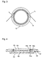
- Fig. 4 is a sectional view of a conventional loudspeaker.
- Cylindrical yoke 101 having a bottom is made of magnetic material, such as iron.
- Frame 102 made of resin is fixed at an outer periphery of yoke 101 by being inserted with pressure or molding.
- Magnet 103 is spaced from inner surface 101a of a side wall of yoke 101 by a predetermined interval and is bonded to the bottom of yoke 101.
- Plate 104 is bonded on an upper surface of magnet 103 and provides magnetic gap 104a between the plate and inner surface 101a of yoke 101.
- Diaphragm 105 is formed by molding a resin sheet.
- Voice coil 106 is positioned in magnetic gap 104a and has an end bonded on a lower surface of diaphragm 105.
- Voice coil 106 is formed by winding a coil wire having a heat welding layer on its surface and coated for insulating and heating the wound wire.
- Coil terminals 106a, both end portions of voice coil 106, are led from between diaphragm 105 and yoke 101, and connected by soldering to respective ends of external terminals 107 integrated with frame 102.
- a sound signal is supplied from an external sound source through external terminals 107 to voice coil 106, and the voice coil 106 and diaphragm 105 vibrate to generate a sound.
- the conventional loudspeaker is to be thin and make a large output for use in a portable communication device, such as a portable telephone, and coil terminals 106a led from between diaphragm 105 and yoke 101 may contact diaphragm 105 or yoke 101 according to a vibration of the loudspeaker driven, thereby producing a noise.
- the conventional loudspeaker accordingly requires a certain interval between diaphragm 105 and yoke 101, thus being prevented from having a reduced size.
- a loudspeaker includes a yoke, a magnet, a plate, a frame, a diaphragm, a voice coil, and an external terminal.
- the yoke has a tube shape having a bottom and a side wall having a first cutout portion formed therein.
- the magnet is spaced from the side wall of the yoke by a predetermined interval and provided on the bottom of the yoke.
- the plate is provided on the magnet and provides a magnetic gap between the plate and an inner surface of the side wall.
- the frame provided at an outer periphery of the yoke.
- the diaphragm has an edge thereof coupled to the frame.
- the voice coil is formed by winding a coil wire in the magnetic gap, and has an edge thereof coupled to the diaphragm.
- the external terminal is provided at the frame and connected to an end portion of the coil wire led from the voice coil.
- the first cutout portion is provided at a position corresponding to the end portion of the coil wire.
- the loudspeaker can be thin since an interval between the diaphragm and the yoke can be short.
- Fig. 1 is a sectional view of a loudspeaker in accordance with an exemplary embodiment of the present invention.
- Fig. 2 is a top view of a voice coil and a yoke, essential parts of the loudspeaker.
- cylindrical yoke 1 having a bottom is made of magnetic material, such as iron.
- Frame 2 made of resin is fixed at an outer periphery of yoke 1 by being inserted with pressure process or molding.
- Magnet 3 is spaced from inner surface 1a of a side wall of yoke 1 by a predetermined interval and is bonded on the bottom of yoke 1.
- Plate 4 is bonded on an upper surface of magnet 3 and forms magnetic gap 4a between the plate and inner surface 1a of yoke 1.
- Diaphragm 5 is formed by molding a resin sheet.
- Voice coil 6 is positioned in magnetic gap 4a and has an end bonded on a lower surface of diaphragm 5.
- Voice coil 6 has an edge bonded on the lower surface of diaphragm 5, and has the other edge positioned in magnetic gap 4a.
- Voice coil 6 is formed by winding a coil wire having a heat welding layer on its surface and coated for insulating and heating the wound wire.
- Lead wires 6a both ends of the coil wire of voice coil 6, are led from the wound coil wire in a direction tangential to the wound coil wire through between diaphragm 5 and yoke 1, and electrically coupled with external terminals 7 at frame 2 by soldering.
- a cylindrical wall of yoke 1 has cutout portions 1c formed under portions around lead wires 6a, the ends of the coil wire of voice coil 6, led from the wound coil wire in a direction tangential to the wound coil wire.
- cutout portions 1c are formed at positions corresponding to lead wires 6a, the ends of the coil wire.
- Lead wires 6a the ends of the coil wire, move in and over cutout portions 1c when lead wires 6a vibrates upward and down ward during driving of the loudspeaker. Therefore, even if an interval between diaphragm 5 and yoke 1 is short, cutout portions 1c maintains an interval between yoke 1 and lead wire 6a, an end of the coil wire, thus allowing the loudspeaker to be thin.
- Fig. 3 is a top view of voice coil 6 and another yoke 1b of a loudspeaker in accordance with the embodiment. Yoke 1b further has cutout portion 1d formed therein.
- Cutout portions 1c reduce a magnetic flux passing through voice coil 6 and may unbalance the magnetic flux.
- diaphragm 5 may roll according to its vibration and collide with yoke 1, thereby generating a noise. In the worst case, a problem that diaphragm 5 is broken may occur.
- Cutout portion 1d reduces the magnetic flux partially as well as cutout portions 1c. Portion 1d cancels the unbalance of the magnetic flux in yoke 1b, hence eliminating the problem.
- yokes 1 and 1b have cylindrical shapes, and however, may have other shapes, such as quadrilateral shapes.
- lead wires 6a of voice coil 6 are placed over cutout portions 1c in Fig. 2, respectively.
- One of lead wires 6a may be placed over cutout portion 1c, and the other lead wire 6a may be led via another path.
- a loudspeaker according to the present invention has a cutout portion formed in a position of a yoke corresponding to a lead wire, an end of a coil wire, led from a voice coil, hence having a thin shape.
Landscapes
- Physics & Mathematics (AREA)
- Engineering & Computer Science (AREA)
- Acoustics & Sound (AREA)
- Signal Processing (AREA)
- Audible-Bandwidth Dynamoelectric Transducers Other Than Pickups (AREA)
Applications Claiming Priority (3)
| Application Number | Priority Date | Filing Date | Title |
|---|---|---|---|
| JP2002258526A JP2004096670A (ja) | 2002-09-04 | 2002-09-04 | スピーカ |
| JP2002258526 | 2002-09-04 | ||
| PCT/JP2003/011295 WO2004023842A1 (fr) | 2002-09-04 | 2003-09-04 | Culasse de haut-parleur |
Publications (2)
| Publication Number | Publication Date |
|---|---|
| EP1448019A1 true EP1448019A1 (fr) | 2004-08-18 |
| EP1448019A4 EP1448019A4 (fr) | 2008-07-09 |
Family
ID=31973029
Family Applications (1)
| Application Number | Title | Priority Date | Filing Date |
|---|---|---|---|
| EP03794224A Withdrawn EP1448019A4 (fr) | 2002-09-04 | 2003-09-04 | Culasse de haut-parleur |
Country Status (7)
| Country | Link |
|---|---|
| US (1) | US7106879B2 (fr) |
| EP (1) | EP1448019A4 (fr) |
| JP (1) | JP2004096670A (fr) |
| KR (1) | KR100663119B1 (fr) |
| CN (1) | CN1579110B (fr) |
| AU (1) | AU2003261929A1 (fr) |
| WO (1) | WO2004023842A1 (fr) |
Families Citing this family (18)
| Publication number | Priority date | Publication date | Assignee | Title |
|---|---|---|---|---|
| TW200629959A (en) * | 2004-09-22 | 2006-08-16 | Citizen Electronics | Electro-dynamic exciter |
| KR100817743B1 (ko) | 2006-09-14 | 2008-03-31 | 주식회사 이엠텍 | 자동화 공정이 용이한 마이크로스피커 |
| WO2009016743A1 (fr) * | 2007-07-31 | 2009-02-05 | Pioneer Corporation | Appareil à haut-parleur |
| CN103987005B (zh) * | 2007-07-31 | 2018-01-12 | 日本先锋公司 | 扬声器装置 |
| WO2009063557A1 (fr) * | 2007-11-14 | 2009-05-22 | Pioneer Corporation | Dispositif de haut-parleur |
| KR101077569B1 (ko) | 2008-02-22 | 2011-10-27 | 주식회사 이엠텍 | 마이크로 스피커 |
| JP4997173B2 (ja) * | 2008-05-13 | 2012-08-08 | ホシデン株式会社 | 電気音響変換器 |
| CN104320743B (zh) * | 2009-01-30 | 2018-01-12 | 日本先锋公司 | 小型扬声器装置 |
| WO2010087007A1 (fr) * | 2009-01-30 | 2010-08-05 | パイオニア株式会社 | Dispositif de haut-parleur |
| CN104581561A (zh) * | 2009-01-30 | 2015-04-29 | 日本先锋公司 | 小型扬声器装置 |
| KR101068783B1 (ko) | 2009-10-09 | 2011-09-30 | 주식회사 이엠텍 | 음향 변환 장치 및 그 제조 방법 |
| TWM388189U (en) * | 2010-01-22 | 2010-09-01 | Fortune Grand Technology Inc | Ultra thin speaker |
| US20140119591A1 (en) * | 2011-07-25 | 2014-05-01 | AAC Microtech(Changzhou) Co., Ltd | Micro-speaker |
| JP6362134B2 (ja) * | 2014-07-31 | 2018-07-25 | 東北パイオニア株式会社 | スピーカ装置 |
| JP6698751B2 (ja) * | 2018-06-19 | 2020-05-27 | 東北パイオニア株式会社 | スピーカ装置 |
| JP2020129821A (ja) * | 2020-04-27 | 2020-08-27 | 東北パイオニア株式会社 | スピーカ装置 |
| JP2022009924A (ja) * | 2020-04-27 | 2022-01-14 | 東北パイオニア株式会社 | スピーカ装置 |
| JP2023055986A (ja) * | 2021-11-02 | 2023-04-18 | 東北パイオニア株式会社 | スピーカ装置 |
Family Cites Families (11)
| Publication number | Priority date | Publication date | Assignee | Title |
|---|---|---|---|---|
| US2216961A (en) * | 1937-09-30 | 1940-10-08 | Rca Corp | Sound translating apparatus |
| US2532413A (en) * | 1946-12-31 | 1950-12-05 | Univ Loudspeakers Inc | Magnet structure for loud-speakers |
| US3358089A (en) * | 1964-06-10 | 1967-12-12 | Gen Electric | Magnet assembly |
| DE2905566A1 (de) * | 1979-02-14 | 1980-08-28 | Standard Elektrik Lorenz Ag | Universelles kalottenlautsprecher- bauelement |
| DE8102303U1 (de) | 1981-01-30 | 1981-07-02 | Grundfos A/S, 8850 Bjerringbro | Kreiselpumpe zur foerderung gashaltiger fluessigkeiten |
| JPS57151096U (fr) | 1981-03-17 | 1982-09-22 | ||
| JP3044831B2 (ja) | 1991-06-11 | 2000-05-22 | 松下電器産業株式会社 | スピーカの製造方法 |
| AT398354B (de) * | 1993-02-26 | 1994-11-25 | Koninkl Philips Electronics Nv | Elektroakustischer wandler mit einer maske |
| JP3680562B2 (ja) * | 1997-10-30 | 2005-08-10 | 松下電器産業株式会社 | 電気−機械−音響変換器及びその製造法 |
| KR20010088726A (ko) | 2001-08-27 | 2001-09-28 | 이형우 | 이어폰 스피커 |
| EP1459811A4 (fr) * | 2001-12-28 | 2008-01-30 | Namiki Precision Jewel Co Ltd | Actionneur vibrant a plusieurs fonctions |
-
2002
- 2002-09-04 JP JP2002258526A patent/JP2004096670A/ja active Pending
-
2003
- 2003-09-04 US US10/493,882 patent/US7106879B2/en not_active Expired - Fee Related
- 2003-09-04 KR KR1020047005246A patent/KR100663119B1/ko not_active Expired - Fee Related
- 2003-09-04 AU AU2003261929A patent/AU2003261929A1/en not_active Abandoned
- 2003-09-04 WO PCT/JP2003/011295 patent/WO2004023842A1/fr not_active Ceased
- 2003-09-04 EP EP03794224A patent/EP1448019A4/fr not_active Withdrawn
- 2003-09-04 CN CN038014300A patent/CN1579110B/zh not_active Expired - Fee Related
Non-Patent Citations (2)
| Title |
|---|
| No further relevant documents disclosed * |
| See also references of WO2004023842A1 * |
Also Published As
| Publication number | Publication date |
|---|---|
| CN1579110B (zh) | 2010-04-28 |
| WO2004023842A1 (fr) | 2004-03-18 |
| KR20040041683A (ko) | 2004-05-17 |
| JP2004096670A (ja) | 2004-03-25 |
| AU2003261929A1 (en) | 2004-03-29 |
| US20040258271A1 (en) | 2004-12-23 |
| EP1448019A4 (fr) | 2008-07-09 |
| US7106879B2 (en) | 2006-09-12 |
| KR100663119B1 (ko) | 2007-01-02 |
| CN1579110A (zh) | 2005-02-09 |
Similar Documents
| Publication | Publication Date | Title |
|---|---|---|
| US7106879B2 (en) | Loudspeaker | |
| KR100545159B1 (ko) | 라우드스피커 | |
| US11950071B2 (en) | Acoustic device | |
| JP2790421B2 (ja) | 電気音響変換器及びその製造方法 | |
| JP2002152882A (ja) | マイクロスピーカの製造方法とそれによるマイクロスピーカ | |
| EP2131607A2 (fr) | Haut-parleur | |
| JP4419352B2 (ja) | スピーカ | |
| US7433486B2 (en) | Speaker and manufacturing method for the same | |
| WO2017166400A1 (fr) | Moteur vibrant et dispositif portable | |
| JP2012119845A (ja) | 電磁型電気音響変換器 | |
| US7010142B2 (en) | Electrical acoustic converter | |
| JP2002171594A (ja) | スピーカ | |
| JP2005269337A (ja) | スピーカ装置 | |
| KR102434194B1 (ko) | 스피커 | |
| US20070223769A1 (en) | Speaker and method making the same | |
| KR20050075788A (ko) | 스피커 | |
| JPH06113395A (ja) | 電気音響変換器 | |
| JP2002186091A (ja) | マイクロスピーカ | |
| JP2615358B2 (ja) | 電気音響変換器及びその製造方法 | |
| JP3966129B2 (ja) | スピーカ | |
| JP2008118477A (ja) | スピーカ、及びスピーカシステム | |
| JP2002354566A (ja) | 多機能型発音体の端子部の製造方法 | |
| KR19980020514U (ko) | 스피커 | |
| KR20030064897A (ko) | 마이크로 스피커 및 그의 제조방법 | |
| JP2002186089A (ja) | マイクロスピーカ |
Legal Events
| Date | Code | Title | Description |
|---|---|---|---|
| PUAI | Public reference made under article 153(3) epc to a published international application that has entered the european phase |
Free format text: ORIGINAL CODE: 0009012 |
|
| 17P | Request for examination filed |
Effective date: 20040427 |
|
| AK | Designated contracting states |
Kind code of ref document: A1 Designated state(s): AT BE BG CH CY CZ DE DK EE ES FI FR GB GR HU IE IT LI LU MC NL PT RO SE SI SK TR |
|
| AX | Request for extension of the european patent |
Extension state: AL LT LV MK |
|
| DAX | Request for extension of the european patent (deleted) | ||
| A4 | Supplementary search report drawn up and despatched |
Effective date: 20080605 |
|
| RIC1 | Information provided on ipc code assigned before grant |
Ipc: H04R 1/06 20060101AFI20080530BHEP Ipc: H04R 9/04 20060101ALN20080530BHEP Ipc: H04R 9/02 20060101ALI20080530BHEP |
|
| RAP1 | Party data changed (applicant data changed or rights of an application transferred) |
Owner name: PANASONIC CORPORATION |
|
| 17Q | First examination report despatched |
Effective date: 20081112 |
|
| RIC1 | Information provided on ipc code assigned before grant |
Ipc: H04R 9/02 20060101AFI20120724BHEP Ipc: H04R 1/06 20060101ALI20120724BHEP |
|
| GRAP | Despatch of communication of intention to grant a patent |
Free format text: ORIGINAL CODE: EPIDOSNIGR1 |
|
| STAA | Information on the status of an ep patent application or granted ep patent |
Free format text: STATUS: THE APPLICATION IS DEEMED TO BE WITHDRAWN |
|
| 18D | Application deemed to be withdrawn |
Effective date: 20130129 |