EP1448864B1 - Elément de maintien et utilisation d'un tel élément - Google Patents
Elément de maintien et utilisation d'un tel élément Download PDFInfo
- Publication number
- EP1448864B1 EP1448864B1 EP02776800A EP02776800A EP1448864B1 EP 1448864 B1 EP1448864 B1 EP 1448864B1 EP 02776800 A EP02776800 A EP 02776800A EP 02776800 A EP02776800 A EP 02776800A EP 1448864 B1 EP1448864 B1 EP 1448864B1
- Authority
- EP
- European Patent Office
- Prior art keywords
- holding element
- specified
- profile
- holding
- cross
- Prior art date
- Legal status (The legal status is an assumption and is not a legal conclusion. Google has not performed a legal analysis and makes no representation as to the accuracy of the status listed.)
- Expired - Lifetime
Links
- 239000000463 material Substances 0.000 claims abstract description 23
- 229910000838 Al alloy Inorganic materials 0.000 claims abstract description 4
- 239000007787 solid Substances 0.000 claims abstract description 4
- 229910000831 Steel Inorganic materials 0.000 claims description 48
- 239000010959 steel Substances 0.000 claims description 48
- 239000012212 insulator Substances 0.000 claims description 26
- 239000004033 plastic Substances 0.000 claims description 21
- 229910052782 aluminium Inorganic materials 0.000 claims description 17
- XAGFODPZIPBFFR-UHFFFAOYSA-N aluminium Chemical compound [Al] XAGFODPZIPBFFR-UHFFFAOYSA-N 0.000 claims description 17
- 238000001125 extrusion Methods 0.000 claims description 11
- 230000002787 reinforcement Effects 0.000 claims description 4
- 239000004952 Polyamide Substances 0.000 claims description 2
- 230000007423 decrease Effects 0.000 claims description 2
- 229920002647 polyamide Polymers 0.000 claims description 2
- 239000000126 substance Substances 0.000 claims 4
- 239000000203 mixture Substances 0.000 claims 1
- 229910052751 metal Inorganic materials 0.000 description 4
- 239000002184 metal Substances 0.000 description 4
- 239000004411 aluminium Substances 0.000 description 3
- 229920000642 polymer Polymers 0.000 description 3
- 239000000969 carrier Substances 0.000 description 2
- 238000010276 construction Methods 0.000 description 2
- 238000004519 manufacturing process Methods 0.000 description 2
- 239000011343 solid material Substances 0.000 description 2
- 238000010521 absorption reaction Methods 0.000 description 1
- 230000000694 effects Effects 0.000 description 1
- 239000000835 fiber Substances 0.000 description 1
- 238000009413 insulation Methods 0.000 description 1
- 238000003754 machining Methods 0.000 description 1
- 150000002739 metals Chemical class 0.000 description 1
- 238000000034 method Methods 0.000 description 1
- 230000007935 neutral effect Effects 0.000 description 1
- 238000003825 pressing Methods 0.000 description 1
- 230000000087 stabilizing effect Effects 0.000 description 1
- 230000007704 transition Effects 0.000 description 1
- 239000013585 weight reducing agent Substances 0.000 description 1
Images


Classifications
-
- E—FIXED CONSTRUCTIONS
- E06—DOORS, WINDOWS, SHUTTERS, OR ROLLER BLINDS IN GENERAL; LADDERS
- E06B—FIXED OR MOVABLE CLOSURES FOR OPENINGS IN BUILDINGS, VEHICLES, FENCES OR LIKE ENCLOSURES IN GENERAL, e.g. DOORS, WINDOWS, BLINDS, GATES
- E06B1/00—Border constructions of openings in walls, floors, or ceilings; Frames to be rigidly mounted in such openings
- E06B1/56—Fastening frames to the border of openings or to similar contiguous frames
- E06B1/60—Fastening frames to the border of openings or to similar contiguous frames by mechanical means, e.g. anchoring means
- E06B1/6007—Fastening frames to the border of openings or to similar contiguous frames by mechanical means, e.g. anchoring means between similar contiguous frames
-
- E—FIXED CONSTRUCTIONS
- E04—BUILDING
- E04D—ROOF COVERINGS; SKY-LIGHTS; GUTTERS; ROOF-WORKING TOOLS
- E04D3/00—Roof covering by making use of flat or curved slabs or stiff sheets
- E04D3/02—Roof covering by making use of flat or curved slabs or stiff sheets of plane slabs, slates, or sheets, or in which the cross-section is unimportant
- E04D3/06—Roof covering by making use of flat or curved slabs or stiff sheets of plane slabs, slates, or sheets, or in which the cross-section is unimportant of glass or other translucent material; Fixing means therefor
- E04D3/08—Roof covering by making use of flat or curved slabs or stiff sheets of plane slabs, slates, or sheets, or in which the cross-section is unimportant of glass or other translucent material; Fixing means therefor with metal glazing bars
- E04D2003/0818—Roof covering by making use of flat or curved slabs or stiff sheets of plane slabs, slates, or sheets, or in which the cross-section is unimportant of glass or other translucent material; Fixing means therefor with metal glazing bars the supporting section of the glazing bar consisting of several parts, e.g. compound sections
- E04D2003/0837—Sections comprising intermediate parts of insulating material
-
- E—FIXED CONSTRUCTIONS
- E06—DOORS, WINDOWS, SHUTTERS, OR ROLLER BLINDS IN GENERAL; LADDERS
- E06B—FIXED OR MOVABLE CLOSURES FOR OPENINGS IN BUILDINGS, VEHICLES, FENCES OR LIKE ENCLOSURES IN GENERAL, e.g. DOORS, WINDOWS, BLINDS, GATES
- E06B3/00—Window sashes, door leaves, or like elements for closing wall or like openings; Layout of fixed or moving closures, e.g. windows in wall or like openings; Features of rigidly-mounted outer frames relating to the mounting of wing frames
- E06B3/04—Wing frames not characterised by the manner of movement
- E06B3/263—Frames with special provision for insulation
- E06B2003/26392—Glazing bars
Definitions
- the invention relates to a holding element with a plurality of bodies, in particular for receiving components such as window frames, facade elements or the like, in which at least one of the body has an extrusion element, and two bodies are thermally separated by an insulator, wherein the extruded element consists of an aluminum alloy and the steel material serves as a reinforcement of the extruded element, as well as a use of such holding elements.
- Retainers with multiple bodies are well known in the art. They serve, for example, to separate a cold area from a warm area, so that in particular a carrier arranged between the two areas reduces heat transfer from the hot area to the cold area via the carrier arranged therebetween. In this case, for example, two carriers are thermally separated from one another by an insulator and connected to one another on the other hand.
- the stabilizing carrier are made of a metal sheet folded into a carrier.
- the sheet may be folded in regions of the carrier twice or more than one above the other.
- the known holding elements reduce the heat transfer from a warm area to a cold area very well.
- they have the disadvantage that they are disadvantageous due to their designed on a sheet metal carrier, especially in the inclusion of other components.
- the sheet-formed carriers are not particularly well suited to accommodate heavier loads, particularly by the attachment of other brackets. Especially at the transition region where a support is attached to an insulator, it may be due to limited strength Of folded from a sheet carrier or a lack of carrier volume often come to an insufficiently stable connection.
- Generic retaining elements are from the WO 99/50511 A and the DE 92 07 578 U known.
- the object of the invention is to further develop such holding elements, so that, inter alia, improves the connection between a carrier and an insulator and in particular thereby the holding element for receiving further brackets, where larger loads can be arranged, is better suited.
- the object is achieved on the one hand by a generic holding element with a material structure in which the material steel is more widely spaced from a cross-sectional inner layer of the holding element is removed as the material aluminum.
- the bodies when larger loads act on the thermally separated bodies of the holding element, it is advantageous for the bodies to consist in particular of an interface to an insulator arranged on them of an extruded element.
- the extrusion element is much better suited to make a more intimate connection to the insulator, so that larger forces between the bodies can easily be transmitted by means of the insulator arranged on them.
- the body can be made by a machining process. Particularly simple and inexpensive, it is, however, if the body according to the invention comprises an extrusion element.
- An extrusion element for example, can be produced outstandingly as a piece by the meter in an extrusion process and is thus particularly advantageous for producing and obstructing.
- the extruded element is structurally particularly easy to make if one of the body consists of a solid material.
- the aluminum alloy has a sufficiently strong structure and is relatively light compared to other metals, which in particular favors the use in facade construction.
- the cross-section of the body is reduced by material recesses. This can be done for example by appropriate holes or corresponding punched out.
- the material recesses may preferably be arranged in areas in which the power flow or the internal stresses are low. For example, for this purpose, the recesses are arranged in the region of the neutral fiber.
- the body has at least one channel extending in the longitudinal direction of the body.
- This channel allows to attach at the body end transverse to this another element such as a cross member.
- this channel can be used as a screw, for example, to attach a component by means of a corresponding screw on the body.
- a cover profile provided with a mandrel by simply pressing the dome into the channel on the body.
- the channel extending in the longitudinal direction of the body is widened to the channel inside.
- this can be between the body and a further profile element a positive connection in a simple manner can be produced.
- At least one body has a positive connection to a thermally isolating the body insulator.
- the insulator comprises a web with corresponding lugs, the insulator can be easily pressed into the channel with the enlarged channel inside to make a high-strength positive connection between the insulator and the body.
- the insulator may also have a channel extending in the longitudinal direction, which then possibly widens to the channel inside.
- At least one body has at least one profile holding web extending in the longitudinal direction of the body.
- the profile holding web can be used to advantageously accommodate further components.
- the other components are attached by a screw or a rivet to the profile holding web of the body.
- one of the body has at least one preferably in the component level projecting component holding web, with the components cooperates.
- a preferred embodiment provides that the component web and a profile holding web of the holding element are arranged at right angles to each other. hereby Among other things, the body of the holding element with their component holding webs can be easily arranged on a component.
- the holding element in particular a profile holding web of at least one body, has at least one bore for receiving a profile element.
- various material recesses may also be present on the profile-holding web of the body for receiving a further profile element, for example a cover profile, such as a cap.
- the material recesses are pre-punched or pre-drilled.
- the profile element has a steel profile.
- the body is made of a solid material, now also solid, heavier parts such as steel profiles can now attach to the holding element without this negative effects on the absorption capacity of the other profile element are to be feared at the holding element.
- the profile element can be designed structurally particularly simple and thus advantageous if the profile element is composed of at least two profile part halves and the profile part halves are preferably made of a sheet folded at least once.
- profile part halves by means of a bolt connection and / or by means of a cap or a Cap extension are connected.
- a preferred bolt connection is for example a screw connection, so that the profile part halves are releasably connected to one another.
- the cap or the cap extension can accommodate the profile part halves so that they clamp the profile part halves against each other and hold.
- a further embodiment provides that the cap relative to the cap extension has a positive connection and / or a frictional connection.
- This connection makes it possible, inter alia, to cover profile elements projecting particularly far from the holding element, for example by means of a cap provided with an extension.
- a standardized cap can optionally be adapted by a corresponding cap extension to the respective profile element conditions.
- the cap or another covering profile on the profile element in a simple embodiment, it is advantageous if at least two profile part halves in the longitudinal direction of the profile element form a preferably extended to the channel inside channel.
- At least one holding device of a cap can be arranged in the channel. This is, for example, a thorn of the cap.
- the profile elements have a holding region deviating from the channel.
- a cap or other cover profile not from the previously described channel is to be included or can, thereby a cap can be particularly easily attached to the holding portion of the profile element.
- At least one profile half has a reduced cross-section, wherein the reduced cross-section is preferably arranged between two spaced retaining regions of two profile elements.
- At least one of the thermally separated bodies is longer in the longitudinal direction than an insulator arranged thereon.
- the holding element has less material volume between the two thermally separated bodies, so that, for example, the thermal conductivity is reduced from a warm area to a cold area due to the smaller volume of material.
- such a construction is material-saving. This can be of economic importance, in particular with a high production output.
- the insulator is made of a polyamide.
- the holding element has a component, preferably two components, on which the body is arranged as a reinforcement.
- a component is part of a window frame.
- window frames are extruded from a plastic to a hollow chamber profile, which can be reinforced by a metal body.
- the retaining element has a varying rigidity in the direction of its maximum cross-sectional extension. This makes it possible to produce the holding element of different materials, so that the holding element can be made very flexible depending on the case of application.
- the holding element in the direction of its maximum cross-sectional extension has a changing modulus of elasticity.
- the holding element has a modulus of elasticity which decreases from a cross-sectional outer layer to a cross-sectional inner layer.
- the retaining element at least partially receives a very rigid and solid outer region, wherein the retaining element towards the core has a lower rigidity and thus is very elastic.
- the holding element has a material sequence which comprises the following materials from a cross-sectional outer layer to a cross-sectional inner layer: steel, aluminum, plastic.
- cross-sectional outer layer is understood in the context of the invention, an area having a maximum distance from the central position of the holding element. If the holding element is designed asymmetrically, the middle position of the holding element falls within the meaning of the invention with the central axis of the insulator of the holding element together.
- cross-sectional inner layer means an area in the vicinity of the central position of the retaining element. If the holding element is designed asymmetrically, the middle position of the holding element falls within the meaning of the invention with the central axis of the insulator of the holding element together.
- one of the bodies is provided with material recesses which, on the one hand, can reduce the thermal conductivity of the body and, on the other hand, make it possible to easily and simply arrange further components to the body and thus, for example, to a high-strength hollow chamber profile.
- the invention is achieved by a use of a retaining element described above for receiving profile elements, in particular also of facade elements or the like.
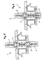
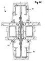
- FIGS. 1 to 11 In each case, a holding element 1 is shown in different embodiments, in which the same components of the holding element 1 are provided with the same reference numerals.
- the holding element 1 essentially comprises two thermally separated bodies 2 and 3 and an insulator 4 arranged between these two bodies 2 and 3.
- the insulator 4 has a bone-like shape with respect to its cross-section, with its two thickened side regions 5 and 6 in each case a running in the longitudinal direction of the body 2 and 3 channel 7 and 8 is arranged.
- the two channels 7 and 8 are widened with respect to their inner side, so that the side regions 5 and 6 are respectively arranged in the channel 7 and in the channel 8 and thus in each case a FonnMedic between the bodies 2 and 3 relative to the insulator 4 is formed.
- the bodies 2 and 3 each have a further channel 9 and 10 along their longitudinal extent.
- the channels 9 and 10 each have a mandrel 11 and 12 of a cover 13 and 14 respectively.
- the mandrel 11 or 12 is of the shape that it has in each case with the channel 9 and 10 a positive connection.
- channel 9 or 10 and the mandrel 11 or 12 cooperate with each other such that only a non-positive connection between the channel 9 and the mandrel 11 or the channel 10 and the mandrel 12 can be present.
- the holding element 1 comprises two components 15 and 16, wherein the cover profiles 13 and 14 form a kind of screen for bridging the spaced-apart components 15 and 16 form.
- the bodies 2 and 3 each have two component holding webs 2A, 2B, 3A and 3B.
- the Bauteilhaltestege 2A, 2B, 3A and 3B are mounted for this purpose in corresponding grooves of the components 15 and 16.
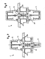
- the holding element 1 may alternatively also have a body 17 deviating from the bodies 2 and 3.
- the body 17 has a channel 18 which has a substantially greater depth than the previously mentioned channels 9 and 10. This makes it possible, the Body 17 stable form.
- An altered cover profile 19 is attached to the retaining element 1 by means of a stronger dome 20.
- the holding element 1 has a second body 21 identical to the first body 17.
- the holding element 1 comprises a body 23, which instead of a channel 9, 10 or 18 for receiving a dome 11, 12 or 20 or in addition to a profile holding web 24 has.
- the profile holding web 24 in this case has a bore 25 in which a screw 26 is arranged, which secures the steel profile 22 to the holding element 1.
- the steel profile 22 consists of two profile part halves 22A and 22B. These two profile part halves 22A and 22B are arranged by means of the screw 26 on the profile holding web 24, thereby forming the steel profile 22 an inwardly narrowing channel 22C.
- holding element 1 for receiving two steel profiles 22 and 27 may comprise two identical bodies 23 and 28.
- the holding element 1 comprises in a further embodiment ( FIG. 6 ) a body 23 and a body 17, so that it is possible to attach a cover 29 by means of the steel profile 22 indirectly to the body 23 and a cover 19 directly to the body 17 of the holding element 1.
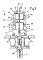
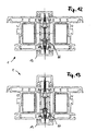
- FIGS. 7 to 11 each show a varied holding element 1 with thermally separated bodies 23 and 28. At these alternatively a plurality of partially different steel profiles 29 to 42 are arranged.
- the steel profiles 29, 31, 32 and 34 to 42 each have a holding region 43 (here only by way of example in FIG. 9 numbered) on which a cover profile is arranged in the form of a cap 44.
- the cap 44 in turn has a plurality of retaining lugs 45 to 52, with which the cap 44 is disposed on the respective holding portion 43 of a steel profile 29, 31, 32 and 34 to 42.
- a cap extension 53 is likewise arranged on the steel profile 34 via retaining lugs 54, 55, 56 and 57.
- the cap 44 and the cap extension 53 are connected to one another in a form-fitting manner by means of two plug connections 58 and 59.
- a steel profile 35 only represents the lowest possible cold or thermal bridge, for example, the profile part halves 60 and 61 of the steel profile 35 in a region 62 each have a cross-sectional reduction.
- the cross-sectional reduction can be provided depending on the embodiment in other areas of a steel section 29, 31, 32 and 34 to 42.
- the steel profile 36 is arranged in a channel 63 of the steel profile 37.
- the channel 63 is formed by the two profile part halves 64 and 65 of the steel profile 37.
- the holding element 1 ( FIG. 11 ) has a cross-sectional outer layer 82 and a cross-sectional inner layer 83 and has a maximum cross-sectional extension 84.
- a holding element 1 wherein at least one body 66 to 71 is made of a plastic, wherein the body 66 to 71, among other things, also the function of a previously described Isolator 4 takes over.
- the body 66 to 71 is designed such that it can accommodate a cover profile 13 and a steel profile 27 or a steel profile 32 on the one hand.
- the body 66 to 71 represent a much worse cold bridge than the aluminum body of the FIGS. 1 to 11 ,
- the holding elements (1) from the FIGS. 12 and 13 each show an embodiment in which a holding element (1) consists of materials such as aluminum and / or plastic.
- the holding element off FIG. 14 On the other hand, it consists of a sequence of material components "plastic, aluminum and steel”.
- the retaining elements from the FIGS. 15 to 17 each have a sequence of material components with the material components steel, plastic, aluminum, steel.
- the holding element off FIG. 18 essentially consists of only a single body 72.
- the body 72 is made of plastic in this embodiment and therefore provides overall excellent insulator properties.
- FIGS. 19 to 21 in each case a holding element 1 is shown, which only has a body 73 to 75, which is made of plastic. As a result, the bodies 73, 74 and 75 have excellent insulation properties.
- profile elements 76 to 81 are arranged.
- a plastic is particularly suitable for their production, since a plastic represents a conceivable bad cold bridge between a hot area and a cold area.
- the invention proposes a holding element with a plurality of bodies, in particular for receiving components such as window frames, facade elements or the like, in which at least one of the bodies has an extrusion element.
Landscapes
- Engineering & Computer Science (AREA)
- Mechanical Engineering (AREA)
- Civil Engineering (AREA)
- Structural Engineering (AREA)
- Wing Frames And Configurations (AREA)
- Adornments (AREA)
- Supports Or Holders For Household Use (AREA)
- Packaging Of Annular Or Rod-Shaped Articles, Wearing Apparel, Cassettes, Or The Like (AREA)
- Gripping On Spindles (AREA)
- Piezo-Electric Or Mechanical Vibrators, Or Delay Or Filter Circuits (AREA)
- Special Wing (AREA)
- Grates (AREA)
- Securing Of Glass Panes Or The Like (AREA)
Claims (30)
- Elément de maintien (1) comprenant plusieurs corps (2, 3 ; 17 ; 21 ; 23 ; 28 ; 66 à 75), en particulier pour réceptionner des éléments de construction (15, 16) tels que cadres de fenêtre, éléments de façade ou similaires, sur lequel au moins l'un des corps (2, 3 ; 17 ; 21 ; 23 ; 28 ; 66 à 75) présente un élément extrudé, et deux corps sont séparés thermiquement par un isolateur, l'élément extrudé étant à base d'un alliage d'aluminium et le matériau acier servant de renfort de l'élément extrudé, caractérisé par une structure de matériau sur laquelle le matériau acier est davantage éloigné d'une couche intérieure de section (83) de l'élément de retenue (1) que le matériau aluminium.
- Elément de maintien (1) selon la revendication 1, caractérisé en ce que l'un des corps (2, 3 ; 17 ; 21 ; 23 ; 28 ; 66 à 75) est à base d'un matériau plein.
- Elément de maintien (1) selon l'une quelconque des revendications 1 à 2, caractérisé en ce que l'un des corps (2, 3 ; 17 ; 21 ; 23 ; 28 ; 66 à 75) présente une section réduite.
- Elément de maintien (1) selon l'une quelconque des revendications 1 à 3, caractérisé en ce qu'une zone de section du corps (2, 3 ; 17 ; 21 ; 23 ; 28 ; 66 à 75) est réduite par des évidements de matériau.
- Elément de maintien (1) selon l'une quelconque des revendications 1 à 4, caractérisé en ce que le corps (2, 3 ; 17 ; 21 ; 23 ; 28 ; 66 à 75) présente au moins un canal (9, 10 ; 18) agencé dans le sens longitudinal du corps (2, 3 ; 17 ; 21 ; 23 ; 28 ; 66 à 75).
- Elément de maintien (1) selon la revendication 5, caractérisé en ce que le canal (9, 10 ; 18) agencé dans le sens longitudinal du corps (2, 3 ; 17 ; 21 ; 23 ; 28 ; 66 à 75) est élargi vers le côté intérieur du canal.
- Elément de maintien (1) selon l'une quelconque des revendications 1 à 6, caractérisé en ce qu'au moins un corps (2, 3 ; 17 ; 21 ; 23 ; 28 ; 66 à 75) présente une liaison par conjugaison de formes avec un isolateur (4) séparant thermiquement les corps (2, 3 ; 17 ; 21 ; 23 ; 28 ; 66 à 75).
- Elément de maintien (1) selon l'une quelconque des revendications 1 à 7, caractérisé en ce qu'au moins un corps (2, 3 ; 17 ; 21 ; 23 ; 28 ; 66 à 75) présente au moins une nervure de maintien de profilé (24) agencée dans le sens longitudinal du corps (2, 3 ; 17 ; 21 ; 23 ; 28 ; 66 à 75).
- Elément de maintien (1) selon l'une quelconque des revendications 1 à 8, caractérisé en ce que l'un des corps (2, 3 ; 17 ; 21 ; 23 ; 28 ; 66 à 75) présente au moins une nervure de maintien d'élément de construction (2A, 2B, 3A, 3B) dépassant de préférence dans le plan de l'élément de construction, qui coopère avec les éléments de construction (15, 16).
- Elément de maintien (1) selon la revendication 9, caractérisé en ce que la nervure de maintien d'élément de construction (2A, 2B, 3A, 3B) et une nervure de maintien de profilé (24) de l'élément de maintien (1) sont disposées à angle droit l'une par rapport à l'autre.
- Elément de maintien (1) selon l'une quelconque des revendications 1 à 10, caractérisé en ce que l'élément de maintien (1), en particulier une nervure de maintien de profilé (24) d'au moins l'un des corps (2, 3 ; 17 ; 21 ; 23 ; 28 ; 66 à 75), présente au moins un perçage (25) pour le logement d'un élément de profilé (22, 27 ; 29, 30 ; 31, 32 ; 76, 77 ; 78, 79 ; 80, 81).
- Elément de maintien (1) selon la revendication 11, caractérisé en ce que l'élément de profilé (22, 27 ; 29, 30 ; 31, 32 ; 76, 77 ; 78, 79 ; 80, 81) présente un profilé en acier (22, 27 ; 29, 30 ; 31, 32).
- Elément de maintien (1) selon l'une quelconque des revendications 1 à 12, caractérisé en ce qu'au moins un corps (2, 3 ; 17 ; 21 ; 23 ; 28 ; 66 à 75) présente une liaison par adhérence des forces avec un élément de profilé (22, 27 ; 29, 30 ; 31, 32 ; 76, 77 ; 78, 79 ; 80, 81).
- Elément de maintien (1) selon l'une quelconque des revendications 11 à 13, caractérisé en ce que l'élément de profilé (22, 27 ; 29, 30 ; 31, 32 ; 76, 77 ; 78, 79 ; 80, 81) est constitué d'au moins deux moitiés partielles de profilé (22A, 22B ; 60, 61 ; 64, 65) et les moitiés partielles de profilé (22A, 22B ; 60, 61 ; 64, 65) sont fabriquées de préférence à partir d'une tôle pliée au moins une fois.
- Elément de maintien (1) selon la revendication 14, caractérisé en ce que les moitiés de partie de profilé (22A, 22B ; 60, 61 ; 64, 65) sont reliées au moyen d'une liaison par boulon et/ou au moyen d'un capuchon (44) ou d'un prolongement de capuchon (53).
- Elément de maintien (1) selon la revendication 15, caractérisé en ce que le capuchon (44) présente par rapport au prolongement de capuchon (53) une liaison par conjugaison de forme et/ou une liaison par frottement.
- Elément de maintien (1) selon l'une quelconque des revendications 10 à 16, caractérisé en ce qu'au moins deux moitiés de partie de profilé (22A, 22B ; 60, 61 ; 64, 65) forment dans le sens longitudinal de l'élément de profilé (22, 27 ; 29, 30 ; 31, 32 ; 76, 77 ; 78, 79 ; 80, 81) un canal (22C ; 63) élargi de préférence vers le côté intérieur du canal.
- Elément de maintien (1) selon la revendication 17, caractérisé en ce qu'au moins un dispositif de maintien d'un capuchon (44) est disposé dans le canal (22C ; 63).
- Elément de maintien (1) selon l'une quelconque des revendications 1 à 18, caractérisé en ce qu'au moins une moitié de partie de profilé (22A, 22B ; 60, 61 ; 64, 65) d'un premier élément de profilé (22, 27 ; 29, 30 ; 31, 32 ; 76, 77 ; 78, 79 ; 80, 81) est disposé entre deux moitiés de partie de profilé (22A, 22B ; 60, 61 ; 64, 65) d'un second élément de profilé (22, 27 ; 29, 30 ; 31, 32 ; 76, 77 ; 78, 79 ; 80, 81).
- Elément de maintien (1) selon l'une quelconque des revendications 1 à 19, caractérisé en ce qu'au moins une moitié de partie de profilé (22A, 22B ; 60, 61 ; 64, 65) d'un élément de profilé (22, 27 ; 29, 30 ; 31, 32 ; 76, 77 ; 78, 79 ; 80, 81) est disposé au moins en partie dans un canal (22C ; 63) d'un autre élément de profilé (22, 27 ; 29, 30 ; 31, 32 ; 76, 77 ; 78, 79 ; 80, 81).
- Elément de maintien (1) selon l'une quelconque des revendications 1 à 20, caractérisé en ce qu'un élément de profilé (22, 27 ; 29, 30 ; 31, 32 ; 76, 77 ; 78, 79 ; 80, 81) présente une zone de maintien (43) s'écartant d'un canal (22C ; 63).
- Elément de maintien (1) selon l'une quelconque des revendications 1 à 21, caractérisé en ce qu'au moins une moitié de partie de profilé (22A, 22B ; 60, 61 ; 64, 65) présente une section réduite, la section réduite étant disposée de préférence entre deux zones de maintien espacées de deux éléments de profilé (22, 27 ; 29, 30 ; 31, 32 ; 76, 77 ; 78, 79 ; 80, 81).
- Elément de maintien (1) selon l'une quelconque des revendications 1 à 22, caractérisé en ce qu'au moins l'un des corps (2, 3 ; 17 ; 21 ; 23 ; 28 ; 66 à 75) est plus long dans le sens de la longueur qu'un isolateur (4) disposé dessus.
- Elément de maintien (1) selon la revendication 23, caractérisé en ce que l'isolateur (4) est fabriqué à base d'un polyamide.
- Elément de maintien (1) selon l'une quelconque des revendications 1 à 24, caractérisé en ce que l'élément de maintien (1) présente un élément de construction, de préférence deux éléments de construction (15, 16), sur lequel le corps (2, 3 ; 17 ; 21 ; 23 ; 28 ; 66 à 75) est disposé comme armature.
- Elément de maintien (1) selon l'une quelconque des revendications 1 à 25, caractérisé en ce que l'élément de maintien (1) présente une rigidité variable en direction de son extension de section (84) maximale.
- Elément de maintien (1) selon l'une quelconque des revendications 1 à 26, caractérisé en ce que l'élément de maintien (1) présente un module d'élasticité variable en direction de son extension de section (84) maximale.
- Elément de maintien (1) selon l'une quelconque des revendications 1 à 27, caractérisé en ce que l'élément de maintien (1) présente une valeur de module d'élasticité qui diminue depuis une couche extérieure de section (82) vers une couche intérieure de section (83).
- Elément de maintien (1) selon l'une quelconque des revendications 1 à 28, caractérisé en ce que l'élément de maintien (1) présente une succession de matériaux qui comprend les matériaux suivants depuis une couche extérieure de section (82) vers une couche intérieure de section (83) : acier, aluminium et plastique.
- Utilisation d'un élément de maintien (1) selon l'une quelconque des revendications 1 à 29 pour le logement d'éléments de profilé (22, 27 ; 29, 30 ; 31, 32 ; 76, 77 ; 78, 79 ; 80, 81), en particulier également d'éléments de façade ou similaires.
Applications Claiming Priority (3)
| Application Number | Priority Date | Filing Date | Title |
|---|---|---|---|
| DE10156898A DE10156898A1 (de) | 2001-11-21 | 2001-11-21 | Halteelement und Verfahren zum Herstellen eines Halteelementes sowie Verwendung von Strangpress-Elementen |
| DE10156898 | 2001-11-21 | ||
| PCT/DE2002/003824 WO2003046323A1 (fr) | 2001-11-21 | 2002-10-11 | Element de maintien, procede de production d'un element de maintien et utilisation d'elements extrudes |
Publications (2)
| Publication Number | Publication Date |
|---|---|
| EP1448864A1 EP1448864A1 (fr) | 2004-08-25 |
| EP1448864B1 true EP1448864B1 (fr) | 2009-12-16 |
Family
ID=7706329
Family Applications (1)
| Application Number | Title | Priority Date | Filing Date |
|---|---|---|---|
| EP02776800A Expired - Lifetime EP1448864B1 (fr) | 2001-11-21 | 2002-10-11 | Elément de maintien et utilisation d'un tel élément |
Country Status (7)
| Country | Link |
|---|---|
| EP (1) | EP1448864B1 (fr) |
| AT (1) | ATE452271T1 (fr) |
| AU (1) | AU2002339356A1 (fr) |
| DE (3) | DE10156898A1 (fr) |
| DK (1) | DK1448864T3 (fr) |
| HU (1) | HUP0402005A2 (fr) |
| WO (1) | WO2003046323A1 (fr) |
Families Citing this family (6)
| Publication number | Priority date | Publication date | Assignee | Title |
|---|---|---|---|---|
| DE20304176U1 (de) | 2003-02-03 | 2003-06-18 | Zentra GmbH, 56291 Wiebelsheim | Verstärkungselement zur Anordnung zwischen zwei Kunststoffprofilen benachbarter Blendrahmen |
| EP1703064A1 (fr) * | 2005-02-10 | 2006-09-20 | Veka AG | Procédé de connecter des fenètres dans une série de fenètres et système de connection |
| DE102007015988B4 (de) | 2007-04-03 | 2018-06-21 | Gealan Fenster-Systeme Gmbh | Kopplungsfalzklotz zur Verbindung von einzelnen Rahmen zu einer Fensterfront |
| DE102007026749A1 (de) * | 2007-06-09 | 2008-12-11 | Profine Gmbh | Verbindungsprofil |
| EP2248982B1 (fr) | 2009-05-07 | 2015-01-28 | Over, Christa | Elément de couplage pour cadres de fenêtres, façades ou analogues |
| DE202009011383U1 (de) | 2009-05-07 | 2010-05-06 | Over, Helmut | Kopplungselement zur Anordnung zwischen zwei Profilen benachbarter Blendrahmen |
Family Cites Families (16)
| Publication number | Priority date | Publication date | Assignee | Title |
|---|---|---|---|---|
| CH471952A (fr) * | 1968-03-08 | 1969-04-30 | Felix Andre | Assemblage d'éléments de construction métalliques pour façades de bâtiments |
| DE3502477A1 (de) * | 1985-01-25 | 1986-08-07 | Julius & August Erbslöh GmbH + Co, 5620 Velbert | Aus mehreren profilstaeben zusammengesetzter traeger, stuetze, pfosten o.dgl., insbesondere fuer fassaden |
| US4686805A (en) * | 1985-02-21 | 1987-08-18 | Jarl Extrusions, Inc. | Panel support |
| DE3614012A1 (de) * | 1986-04-25 | 1987-11-05 | Happich Gmbh Gebr | Einrichtung zum verkleiden eines an einer fahrzeugkarosserie vorstehend ausgebildeten, am freien endbereich durchlaufend abgewinkelten flanschs |
| DE8812237U1 (de) * | 1988-09-28 | 1988-11-17 | Over, Helmut, 53909 Zülpich | Verbindungsträger zur Befestigung von Rahmenkonstruktionen |
| DE3841334C2 (de) * | 1988-12-08 | 1997-08-28 | Schueco Int Gmbh & Co | Fenster, Tür oder Festverglasung |
| US5038537A (en) * | 1989-02-21 | 1991-08-13 | Harry Frambach | Window system and structure |
| DE4210998A1 (de) * | 1991-04-03 | 1992-10-22 | Papst Hans Dieter | Schutzgitter mit festen rahmenteilen und halteelement hierfuer |
| DE4140458C2 (de) * | 1991-12-05 | 1997-04-10 | Mannesmann Ag | Glasfassade für vertikale, diagonale und horizontale Bausysteme |
| DE9207578U1 (de) * | 1992-06-04 | 1992-08-27 | Lenz, Hermann, 3554 Gladenbach | Fassadensystem |
| DE4344863C2 (de) * | 1993-12-29 | 1995-10-26 | Schroff Gmbh | Befestigungsanordnung |
| DE4447208C2 (de) * | 1994-12-30 | 1998-07-16 | Alfer Aluminium Gmbh | Hakenträgersystem |
| DE19535757A1 (de) * | 1995-09-26 | 1997-03-27 | Transnorm System Gmbh | Flächiges Tragelement |
| DE29604633U1 (de) * | 1996-03-13 | 1996-05-30 | Over, Helmut, 53909 Zülpich | Träger für Verglasung |
| DE19802020A1 (de) * | 1998-01-21 | 1999-07-22 | Krauss Innovation Ltd | Vorrichtung zur Halterung von Glasscheiben |
| AU3594499A (en) * | 1998-03-27 | 1999-10-18 | Helmut Over | Support for door frames, facades or the same |
-
2001
- 2001-11-21 DE DE10156898A patent/DE10156898A1/de not_active Withdrawn
-
2002
- 2002-10-11 AU AU2002339356A patent/AU2002339356A1/en not_active Abandoned
- 2002-10-11 WO PCT/DE2002/003824 patent/WO2003046323A1/fr not_active Ceased
- 2002-10-11 AT AT02776800T patent/ATE452271T1/de active
- 2002-10-11 EP EP02776800A patent/EP1448864B1/fr not_active Expired - Lifetime
- 2002-10-11 DK DK02776800.1T patent/DK1448864T3/da active
- 2002-10-11 HU HU0402005A patent/HUP0402005A2/hu unknown
- 2002-10-11 DE DE50214109T patent/DE50214109D1/de not_active Expired - Lifetime
- 2002-10-11 DE DE10295524T patent/DE10295524D2/de not_active Expired - Fee Related
Also Published As
| Publication number | Publication date |
|---|---|
| WO2003046323A1 (fr) | 2003-06-05 |
| DE10156898A1 (de) | 2003-05-28 |
| EP1448864A1 (fr) | 2004-08-25 |
| ATE452271T1 (de) | 2010-01-15 |
| HUP0402005A2 (hu) | 2005-01-28 |
| AU2002339356A1 (en) | 2003-06-10 |
| DE50214109D1 (de) | 2010-01-28 |
| DK1448864T3 (da) | 2010-04-26 |
| DE10295524D2 (de) | 2004-09-23 |
Similar Documents
| Publication | Publication Date | Title |
|---|---|---|
| EP0146716B1 (fr) | Superstructure | |
| EP0479401B1 (fr) | Poutre de choc | |
| EP0278292B1 (fr) | Arbre creux et son procédé de fabrication | |
| EP0749378B1 (fr) | Raclette d'essuie-glace | |
| DE102012020432B3 (de) | Schwellerstruktur für eine Fahrzeugkarosserie | |
| EP3898296A1 (fr) | Bras de suspension pour un véhicule automobile | |
| DE10329017B4 (de) | Tragekonstruktion, insbesondere für Karosserieaufbauten von Fahrzeugen aus rechteckigen Hohlprofilen | |
| EP1504983A1 (fr) | Châssis auxiliaire pour véhicules | |
| DE19945160A1 (de) | Fahrzeuglenksäule | |
| EP1868885B1 (fr) | Element structurel d'un avion comportant une cavite et un element de drainage | |
| DE2321915A1 (de) | Zusammenschiebbare lenksaeulenanordnung | |
| EP1448864B1 (fr) | Elément de maintien et utilisation d'un tel élément | |
| DE202008000574U1 (de) | Verbindungseinrichtung | |
| EP0418718A1 (fr) | Manchonnage amortissant hydrauliquement | |
| EP2030869A2 (fr) | Support en tant que traverse ou longeron dans un véhicule automobile | |
| EP1580343B1 (fr) | Élément pour le joint d'about de profilés | |
| DE102005011834B4 (de) | Seitlicher Dachrahmen für ein Kraftfahrzeug | |
| DE202017105765U1 (de) | Befestigungsvorrichtung zur Befestigung von mindestens einem Bauteil | |
| EP1730016A1 (fr) | Support transversal ou composant structurel pour vehicule automobile | |
| DE10130794A1 (de) | Strukturteil eines Kraftfahrzeugkörpers und Verfahren zu dessen Herstellung | |
| DE202005021480U1 (de) | Verbindungselemente für Platten, insbesondere aus Glas, zur Befestigung derselben und derart ausgerüstete Platten | |
| DE19805804A1 (de) | Fahrzeugkarosserie | |
| DE102015220088B3 (de) | Verbindung eines Einsatzteils mit einem Hohlprofil | |
| DE10108352B4 (de) | Strukturbauelement für den Fahrzeugbau | |
| EP1491696B1 (fr) | Système d'assemblage de profilés |
Legal Events
| Date | Code | Title | Description |
|---|---|---|---|
| PUAI | Public reference made under article 153(3) epc to a published international application that has entered the european phase |
Free format text: ORIGINAL CODE: 0009012 |
|
| 17P | Request for examination filed |
Effective date: 20040621 |
|
| AK | Designated contracting states |
Kind code of ref document: A1 Designated state(s): AT BE BG CH CY CZ DE DK EE ES FI FR GB GR IE IT LI LU MC NL PT SE SK TR |
|
| AX | Request for extension of the european patent |
Extension state: AL LT LV MK RO SI |
|
| 17Q | First examination report despatched |
Effective date: 20080721 |
|
| GRAP | Despatch of communication of intention to grant a patent |
Free format text: ORIGINAL CODE: EPIDOSNIGR1 |
|
| RTI1 | Title (correction) |
Free format text: HOLDING ELEMENT UND USE OF SUCH A HOLDING ELEMENT |
|
| GRAS | Grant fee paid |
Free format text: ORIGINAL CODE: EPIDOSNIGR3 |
|
| GRAA | (expected) grant |
Free format text: ORIGINAL CODE: 0009210 |
|
| AK | Designated contracting states |
Kind code of ref document: B1 Designated state(s): AT BE BG CH CY CZ DE DK EE ES FI FR GB GR IE IT LI LU MC NL PT SE SK TR |
|
| AX | Request for extension of the european patent |
Extension state: AL LT LV MK RO SI |
|
| REG | Reference to a national code |
Ref country code: GB Ref legal event code: FG4D Free format text: NOT ENGLISH |
|
| REG | Reference to a national code |
Ref country code: CH Ref legal event code: EP |
|
| REG | Reference to a national code |
Ref country code: IE Ref legal event code: FG4D |
|
| REF | Corresponds to: |
Ref document number: 50214109 Country of ref document: DE Date of ref document: 20100128 Kind code of ref document: P |
|
| REG | Reference to a national code |
Ref country code: SE Ref legal event code: TRGR |
|
| REG | Reference to a national code |
Ref country code: NL Ref legal event code: T3 |
|
| REG | Reference to a national code |
Ref country code: CH Ref legal event code: NV Representative=s name: E. BLUM & CO. AG PATENT- UND MARKENANWAELTE VSP |
|
| REG | Reference to a national code |
Ref country code: DK Ref legal event code: T3 |
|
| PG25 | Lapsed in a contracting state [announced via postgrant information from national office to epo] |
Ref country code: FI Free format text: LAPSE BECAUSE OF FAILURE TO SUBMIT A TRANSLATION OF THE DESCRIPTION OR TO PAY THE FEE WITHIN THE PRESCRIBED TIME-LIMIT Effective date: 20091216 |
|
| LTIE | Lt: invalidation of european patent or patent extension |
Effective date: 20091216 |
|
| REG | Reference to a national code |
Ref country code: IE Ref legal event code: FD4D |
|
| PG25 | Lapsed in a contracting state [announced via postgrant information from national office to epo] |
Ref country code: EE Free format text: LAPSE BECAUSE OF FAILURE TO SUBMIT A TRANSLATION OF THE DESCRIPTION OR TO PAY THE FEE WITHIN THE PRESCRIBED TIME-LIMIT Effective date: 20091216 Ref country code: PT Free format text: LAPSE BECAUSE OF FAILURE TO SUBMIT A TRANSLATION OF THE DESCRIPTION OR TO PAY THE FEE WITHIN THE PRESCRIBED TIME-LIMIT Effective date: 20100416 Ref country code: BG Free format text: LAPSE BECAUSE OF FAILURE TO SUBMIT A TRANSLATION OF THE DESCRIPTION OR TO PAY THE FEE WITHIN THE PRESCRIBED TIME-LIMIT Effective date: 20100316 Ref country code: ES Free format text: LAPSE BECAUSE OF FAILURE TO SUBMIT A TRANSLATION OF THE DESCRIPTION OR TO PAY THE FEE WITHIN THE PRESCRIBED TIME-LIMIT Effective date: 20100327 Ref country code: IE Free format text: LAPSE BECAUSE OF FAILURE TO SUBMIT A TRANSLATION OF THE DESCRIPTION OR TO PAY THE FEE WITHIN THE PRESCRIBED TIME-LIMIT Effective date: 20091216 |
|
| PG25 | Lapsed in a contracting state [announced via postgrant information from national office to epo] |
Ref country code: CZ Free format text: LAPSE BECAUSE OF FAILURE TO SUBMIT A TRANSLATION OF THE DESCRIPTION OR TO PAY THE FEE WITHIN THE PRESCRIBED TIME-LIMIT Effective date: 20091216 Ref country code: SK Free format text: LAPSE BECAUSE OF FAILURE TO SUBMIT A TRANSLATION OF THE DESCRIPTION OR TO PAY THE FEE WITHIN THE PRESCRIBED TIME-LIMIT Effective date: 20091216 |
|
| PLBE | No opposition filed within time limit |
Free format text: ORIGINAL CODE: 0009261 |
|
| STAA | Information on the status of an ep patent application or granted ep patent |
Free format text: STATUS: NO OPPOSITION FILED WITHIN TIME LIMIT |
|
| PG25 | Lapsed in a contracting state [announced via postgrant information from national office to epo] |
Ref country code: GR Free format text: LAPSE BECAUSE OF FAILURE TO SUBMIT A TRANSLATION OF THE DESCRIPTION OR TO PAY THE FEE WITHIN THE PRESCRIBED TIME-LIMIT Effective date: 20100317 Ref country code: CY Free format text: LAPSE BECAUSE OF FAILURE TO SUBMIT A TRANSLATION OF THE DESCRIPTION OR TO PAY THE FEE WITHIN THE PRESCRIBED TIME-LIMIT Effective date: 20091216 |
|
| 26N | No opposition filed |
Effective date: 20100917 |
|
| PG25 | Lapsed in a contracting state [announced via postgrant information from national office to epo] |
Ref country code: IT Free format text: LAPSE BECAUSE OF FAILURE TO SUBMIT A TRANSLATION OF THE DESCRIPTION OR TO PAY THE FEE WITHIN THE PRESCRIBED TIME-LIMIT Effective date: 20091216 |
|
| BERE | Be: lapsed |
Owner name: OVER, HELMUT Effective date: 20101031 |
|
| PG25 | Lapsed in a contracting state [announced via postgrant information from national office to epo] |
Ref country code: BE Free format text: LAPSE BECAUSE OF NON-PAYMENT OF DUE FEES Effective date: 20101031 |
|
| PG25 | Lapsed in a contracting state [announced via postgrant information from national office to epo] |
Ref country code: TR Free format text: LAPSE BECAUSE OF FAILURE TO SUBMIT A TRANSLATION OF THE DESCRIPTION OR TO PAY THE FEE WITHIN THE PRESCRIBED TIME-LIMIT Effective date: 20091216 |
|
| REG | Reference to a national code |
Ref country code: DE Ref legal event code: R082 Ref document number: 50214109 Country of ref document: DE Representative=s name: PATENTANWALTSKANZLEI LIERMANN-CASTELL, PATENTA, DE |
|
| REG | Reference to a national code |
Ref country code: DE Ref legal event code: R081 Ref document number: 50214109 Country of ref document: DE Owner name: OVER, CHRISTA, DE Free format text: FORMER OWNER: OVER, HELMUT, 53909 ZUELPICH, DE Effective date: 20130809 Ref country code: DE Ref legal event code: R082 Ref document number: 50214109 Country of ref document: DE Representative=s name: PATENTANWALTSKANZLEI LIERMANN-CASTELL, PATENTA, DE Effective date: 20130809 Ref country code: DE Ref legal event code: R082 Ref document number: 50214109 Country of ref document: DE Representative=s name: PATENTANWALTSKANZLEI LIERMANN-CASTELL, DE Effective date: 20130809 |
|
| REG | Reference to a national code |
Ref country code: FR Ref legal event code: PLFP Year of fee payment: 14 |
|
| PGFP | Annual fee paid to national office [announced via postgrant information from national office to epo] |
Ref country code: LU Payment date: 20151023 Year of fee payment: 14 |
|
| PGFP | Annual fee paid to national office [announced via postgrant information from national office to epo] |
Ref country code: DK Payment date: 20151021 Year of fee payment: 14 |
|
| PGFP | Annual fee paid to national office [announced via postgrant information from national office to epo] |
Ref country code: GB Payment date: 20151021 Year of fee payment: 14 |
|
| PGFP | Annual fee paid to national office [announced via postgrant information from national office to epo] |
Ref country code: NL Payment date: 20151021 Year of fee payment: 14 Ref country code: SE Payment date: 20151021 Year of fee payment: 14 Ref country code: MC Payment date: 20151014 Year of fee payment: 14 |
|
| PGFP | Annual fee paid to national office [announced via postgrant information from national office to epo] |
Ref country code: DE Payment date: 20151221 Year of fee payment: 14 |
|
| REG | Reference to a national code |
Ref country code: FR Ref legal event code: PLFP Year of fee payment: 15 |
|
| REG | Reference to a national code |
Ref country code: DE Ref legal event code: R119 Ref document number: 50214109 Country of ref document: DE |
|
| REG | Reference to a national code |
Ref country code: DK Ref legal event code: EBP Effective date: 20161031 |
|
| REG | Reference to a national code |
Ref country code: NL Ref legal event code: MM Effective date: 20161101 |
|
| GBPC | Gb: european patent ceased through non-payment of renewal fee |
Effective date: 20161011 |
|
| PG25 | Lapsed in a contracting state [announced via postgrant information from national office to epo] |
Ref country code: MC Free format text: LAPSE BECAUSE OF NON-PAYMENT OF DUE FEES Effective date: 20161031 |
|
| PG25 | Lapsed in a contracting state [announced via postgrant information from national office to epo] |
Ref country code: DE Free format text: LAPSE BECAUSE OF NON-PAYMENT OF DUE FEES Effective date: 20170503 Ref country code: GB Free format text: LAPSE BECAUSE OF NON-PAYMENT OF DUE FEES Effective date: 20161011 |
|
| PG25 | Lapsed in a contracting state [announced via postgrant information from national office to epo] |
Ref country code: SE Free format text: LAPSE BECAUSE OF NON-PAYMENT OF DUE FEES Effective date: 20161012 Ref country code: LU Free format text: LAPSE BECAUSE OF NON-PAYMENT OF DUE FEES Effective date: 20161011 Ref country code: NL Free format text: LAPSE BECAUSE OF NON-PAYMENT OF DUE FEES Effective date: 20161101 |
|
| REG | Reference to a national code |
Ref country code: FR Ref legal event code: PLFP Year of fee payment: 16 |
|
| PG25 | Lapsed in a contracting state [announced via postgrant information from national office to epo] |
Ref country code: DK Free format text: LAPSE BECAUSE OF NON-PAYMENT OF DUE FEES Effective date: 20161031 |
|
| PGFP | Annual fee paid to national office [announced via postgrant information from national office to epo] |
Ref country code: FR Payment date: 20171024 Year of fee payment: 16 |
|
| PGFP | Annual fee paid to national office [announced via postgrant information from national office to epo] |
Ref country code: CH Payment date: 20171019 Year of fee payment: 16 |
|
| PGFP | Annual fee paid to national office [announced via postgrant information from national office to epo] |
Ref country code: AT Payment date: 20181022 Year of fee payment: 17 |
|
| REG | Reference to a national code |
Ref country code: CH Ref legal event code: PL |
|
| PG25 | Lapsed in a contracting state [announced via postgrant information from national office to epo] |
Ref country code: CH Free format text: LAPSE BECAUSE OF NON-PAYMENT OF DUE FEES Effective date: 20181031 Ref country code: FR Free format text: LAPSE BECAUSE OF NON-PAYMENT OF DUE FEES Effective date: 20181031 Ref country code: LI Free format text: LAPSE BECAUSE OF NON-PAYMENT OF DUE FEES Effective date: 20181031 |
|
| REG | Reference to a national code |
Ref country code: AT Ref legal event code: MM01 Ref document number: 452271 Country of ref document: AT Kind code of ref document: T Effective date: 20191011 |
|
| PG25 | Lapsed in a contracting state [announced via postgrant information from national office to epo] |
Ref country code: AT Free format text: LAPSE BECAUSE OF NON-PAYMENT OF DUE FEES Effective date: 20191011 |