EP1448879B1 - Motor mit eigenzündung mit gesteuerter homogener ladung - Google Patents
Motor mit eigenzündung mit gesteuerter homogener ladung Download PDFInfo
- Publication number
- EP1448879B1 EP1448879B1 EP02797102A EP02797102A EP1448879B1 EP 1448879 B1 EP1448879 B1 EP 1448879B1 EP 02797102 A EP02797102 A EP 02797102A EP 02797102 A EP02797102 A EP 02797102A EP 1448879 B1 EP1448879 B1 EP 1448879B1
- Authority
- EP
- European Patent Office
- Prior art keywords
- piston
- engine
- combustion
- head
- extended position
- Prior art date
- Legal status (The legal status is an assumption and is not a legal conclusion. Google has not performed a legal analysis and makes no representation as to the accuracy of the status listed.)
- Expired - Lifetime
Links
- 230000006835 compression Effects 0.000 claims description 61
- 238000007906 compression Methods 0.000 claims description 61
- 238000002485 combustion reaction Methods 0.000 claims description 50
- 238000000034 method Methods 0.000 claims description 27
- 239000012530 fluid Substances 0.000 claims description 21
- 239000000203 mixture Substances 0.000 claims description 16
- 239000000567 combustion gas Substances 0.000 claims description 5
- 238000007599 discharging Methods 0.000 claims 1
- 239000000446 fuel Substances 0.000 description 18
- MWUXSHHQAYIFBG-UHFFFAOYSA-N Nitric oxide Chemical compound O=[N] MWUXSHHQAYIFBG-UHFFFAOYSA-N 0.000 description 12
- QVGXLLKOCUKJST-UHFFFAOYSA-N atomic oxygen Chemical compound [O] QVGXLLKOCUKJST-UHFFFAOYSA-N 0.000 description 5
- 230000000977 initiatory effect Effects 0.000 description 5
- 239000001301 oxygen Substances 0.000 description 5
- 229910052760 oxygen Inorganic materials 0.000 description 5
- 239000013618 particulate matter Substances 0.000 description 5
- IJGRMHOSHXDMSA-UHFFFAOYSA-N Atomic nitrogen Chemical compound N#N IJGRMHOSHXDMSA-UHFFFAOYSA-N 0.000 description 2
- 239000007789 gas Substances 0.000 description 2
- 239000000376 reactant Substances 0.000 description 2
- 230000001419 dependent effect Effects 0.000 description 1
- 238000005516 engineering process Methods 0.000 description 1
- 239000003344 environmental pollutant Substances 0.000 description 1
- 239000008240 homogeneous mixture Substances 0.000 description 1
- 238000005259 measurement Methods 0.000 description 1
- 229910052757 nitrogen Inorganic materials 0.000 description 1
- TVMXDCGIABBOFY-UHFFFAOYSA-N octane Chemical compound CCCCCCCC TVMXDCGIABBOFY-UHFFFAOYSA-N 0.000 description 1
- 230000035515 penetration Effects 0.000 description 1
- 231100000719 pollutant Toxicity 0.000 description 1
Images
Classifications
-
- F—MECHANICAL ENGINEERING; LIGHTING; HEATING; WEAPONS; BLASTING
- F02—COMBUSTION ENGINES; HOT-GAS OR COMBUSTION-PRODUCT ENGINE PLANTS
- F02D—CONTROLLING COMBUSTION ENGINES
- F02D41/00—Electrical control of supply of combustible mixture or its constituents
- F02D41/30—Controlling fuel injection
- F02D41/3011—Controlling fuel injection according to or using specific or several modes of combustion
- F02D41/3017—Controlling fuel injection according to or using specific or several modes of combustion characterised by the mode(s) being used
- F02D41/3035—Controlling fuel injection according to or using specific or several modes of combustion characterised by the mode(s) being used a mode being the premixed charge compression-ignition mode
- F02D41/3041—Controlling fuel injection according to or using specific or several modes of combustion characterised by the mode(s) being used a mode being the premixed charge compression-ignition mode with means for triggering compression ignition, e.g. spark plug
-
- F—MECHANICAL ENGINEERING; LIGHTING; HEATING; WEAPONS; BLASTING
- F02—COMBUSTION ENGINES; HOT-GAS OR COMBUSTION-PRODUCT ENGINE PLANTS
- F02B—INTERNAL-COMBUSTION PISTON ENGINES; COMBUSTION ENGINES IN GENERAL
- F02B1/00—Engines characterised by fuel-air mixture compression
- F02B1/12—Engines characterised by fuel-air mixture compression with compression ignition
-
- F—MECHANICAL ENGINEERING; LIGHTING; HEATING; WEAPONS; BLASTING
- F02—COMBUSTION ENGINES; HOT-GAS OR COMBUSTION-PRODUCT ENGINE PLANTS
- F02B—INTERNAL-COMBUSTION PISTON ENGINES; COMBUSTION ENGINES IN GENERAL
- F02B75/00—Other engines
- F02B75/04—Engines with variable distances between pistons at top dead-centre positions and cylinder heads
- F02B75/041—Engines with variable distances between pistons at top dead-centre positions and cylinder heads by means of cylinder or cylinderhead positioning
- F02B75/042—Engines with variable distances between pistons at top dead-centre positions and cylinder heads by means of cylinder or cylinderhead positioning the cylinderhead comprising a counter-piston
-
- Y—GENERAL TAGGING OF NEW TECHNOLOGICAL DEVELOPMENTS; GENERAL TAGGING OF CROSS-SECTIONAL TECHNOLOGIES SPANNING OVER SEVERAL SECTIONS OF THE IPC; TECHNICAL SUBJECTS COVERED BY FORMER USPC CROSS-REFERENCE ART COLLECTIONS [XRACs] AND DIGESTS
- Y02—TECHNOLOGIES OR APPLICATIONS FOR MITIGATION OR ADAPTATION AGAINST CLIMATE CHANGE
- Y02T—CLIMATE CHANGE MITIGATION TECHNOLOGIES RELATED TO TRANSPORTATION
- Y02T10/00—Road transport of goods or passengers
- Y02T10/10—Internal combustion engine [ICE] based vehicles
- Y02T10/12—Improving ICE efficiencies
Definitions
- the invention relates to method and apparatus for controlling initiation of homogeneous-charge, compression-ignition (HCCI) over a wide range of load in diesel-cycle engines to reduce NO x and PM emissions.
- HCCI homogeneous-charge, compression-ignition
- the field of application is internal combustion engines for motor vehicles.
- diesel-cycle engines in motor vehicles greatly adds to the atmospheric presence of pollutants such as oxides of nitrogen and particulate matter.
- Conventional diesel-cycle engines emit nitrogen oxide (NO x ) and particulate matter (PM) substantially in excess of levels achievable in Otto-cycle (e.g., gasoline homogeneous-charge) engines, yet diesel-cycle engines achieve substantially better fuel economy.
- Otto-cycle e.g., gasoline homogeneous-charge
- diesel-cycle engines achieve substantially better fuel economy.
- Diesel-cycle engines dominate the heavy-duty truck market and much of the off-road commercial vehicle market, with growing penetration in light duty trucks.
- technology which could substantially reduce NO x and PM emissions in a cost effective and efficient manner from diesel-cycle engines is highly desired.
- a substantial body of prior art describes the operation of homogenous-charge, compression-ignition (HCCI) engines.
- a homogenous-charge of fuel and air (oxygen) will auto-ignite during compression at a particular compression level (e.g., compression ratio), depending primarily on (1) the nature of the fuel (e.g., octane level), (2) concentration of the reactants (i.e., fuel and oxygen), and (3) the initial temperature of the charge mixture of fuel and air (including any recirculated exhaust gas).
- the compression of the charge both increases temperature and concentration of reactants, as well as increases pressure.
- There is one compression ratio for a given set of starting conditions where auto-ignition i.e., compression ignition
- Publication WO 00/09871 A relates to a piston-cylinder combustion engine that uses a premixed fuel/air mixture and a compression ignition.
- the present invention achieves control of the initiation of HCCI by mechanically controlling the engine compression ratio during engine operation so that for a particular set of operating conditions the initiation of HCCI will occur at an optimum condition when the piston has reached near TDC, generally within five crank angle degrees before to ten crank angle degrees after TDC depending on engine speed.
- One method of controlling engine compression ratio is to change the stroke of the piston by means such as; (1) raising or lowering the centerline of the crankshaft, (2) changing the effective length of the piston- to-crankshaft connecting rod, or (3) changing the effective length of the piston (and thus its displaced volume) above the piston/rod attachment.
- Another method of controlling engine compression ratio is to vary the height of the engine head above the TDC position of the piston.
- the present invention provides a diesel-cycle engine (capable of operating on a variety of fuels including gasoline and diesel) including a plurality of combustion cylinders and a first piston reciprocably mounted within each of the combustion cylinders.
- the piston presents a first face defining one boundary of a combustion chamber within a combustion cylinder and a head covers the combustion cylinders with a plurality of cylindrical recesses, each cylindrical recess opening into a respective one of the combustion cylinders.
- a second piston is reciprocably mounted in each of the cylindrical recesses in the head and presents a second piston face defining a second boundary of the combustion chamber.
- a fuel-air mixture is formed in a conventional manner to strive for a homogeneous mixture, with fuel injected into the air charge earlier than in a conventional diesel engine.
- a fuel-air mixture can be introduced into each cylinder, in succession, through a selected one of plural intake ports formed in the head, as practiced in conventional gasoline engines, or the fuel may be added to the air charge during air intake or compression.
- a controller is provided for moving the second piston from a retracted position outward in the cylindrical recess in the head, to an extended position, during the end of each compression stroke (generally within five crank angle degrees before piston TDC) or the beginning of the expansion stroke (generally within ten crank angle degrees after piston TDC) of said piston, to reduce the volume of the combustion chamber and increase the compression ratio to a level causing auto-ignition of the fuel-air mixture.
- the engine is further provided with a sensor for determining power demanded of the engine and with a controller for controlling the extended position of the second piston and thereby varying the compression ratio in accordance with the sensed power demand.
- the first piston has a face defining one boundary of the combustion chamber and a cylindrical recess formed therein axially aligned with a cylindrical recess in the engine head and, preferably, of the same diameter as the cylindrical recess in the engine head.
- the second piston is a free-floating double face piston having one face defining the second boundary of the combustion chamber and a third face defining a control chamber in cooperation with a cylindrical recess in the engine head.
- An inlet port and an outlet port are provided for introducing hydraulic fluid to and exhausting hydraulic fluid from the control chamber.
- Each of these ports connects to a line having an on/off control valve therein whereby the second piston can be moved to its extended position by introduction of high pressure fluid into the control chamber and in another embodiment can be returned to its retracted position by the force of the expanding combustion gases in a power stroke.
- the present invention provides a method for operation of the above-described engine, the method including moving the second piston outward from its retracted position to an extended position within a cylindrical recess within the head, to initiate each combustion stroke of the first piston, after the first piston has reached a point near top dead center, to reduce the volume of the combustion chamber and to increase the compression ratio to a level causing auto-ignition of a fuel-air mixture within the combustion chamber.
- the method of the present invention preferably includes the sensing of power demanded of the engine, e.g., by depression of an accelerator pedal, and controlling the extended position of the second piston, and thereby controlling the compression ratio, in accordance with the sensed power demand.
- the preferred embodiment of the present invention maintains a high expansion ratio to maintain high efficiency by providing a method of operation and a means for final charge compression when the piston has already reached near TDC. This avoids engine knocking while providing sufficient compression to auto-ignite low fuel concentrations (light load) under even low charge temperatures.
- a fuel that would auto-ignite at a compression ratio of 6 under conditions of high load (maximum fuel concentration) and maximum expected initial charge temperature would not auto-ignite at lower loads or temperatures and would thus need a means to increase compression ratio under those conditions.
- a preferred embodiment of the present invention would provide a conventional piston and crankshaft mechanism with a compression ratio of 6 in the conventional manner, but would also provide a movable surface for the combustion, chamber, for example a second piston mounted in the head, which would be able to rapidly further reduce the volume of the combustion chamber (and thus increase compression ratio) after the piston has reached near TDC.
- the present invention thus provides a method of operation and a means for controlling HCCI at or near piston TDC while maintaining high compression and expansion ratios necessary to maintain high engine efficiency over a range of operating conditions.
- the aim and objects of this invention are achieved by the methods and systems according to independent claim 1 and any other independent claims of this invention. Further details may be found in the remaining dependent claims.
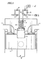
- the solo drawing figure is a schematic view of a preferred embodiment of one combustion chamber of an engine in accordance with the present invention.
- piston bowl 14 intake air and fuel (homogeneous charge) enter through engine intake port 11 and exhaust gases exit the engine through exhaust port 12 in a conventional manner, whether operating in a 4 stroke or a 2 stroke cycle.
- Piston 13 is driven with reciprocating motion to drive a crankshaft (not shown) in a conventional manner.
- the top or "first face" of the piston is provided with a central recess 14 hereinafter referred to as a "piston bowl.”
- the volume of piston bowl 14 is sized to provide a high compression and expansion ratio (e.g., 19) of a conventional Diesel-cycle engine, assuming a conventional flat engine head.
- a second recess (a cylindrical chamber) 15 with a movable surface 16 is formed in the combustion chamber side of piston 17, i.e., in the head.
- the effective volume of recess 15 can be reduced to zero or expanded to a volume sufficient to prevent auto-ignition of a particular homogeneous fuel-air mixture at stoichiometric conditions and the maximum expected initial, pre-compression temperature (e.g., to a volume which provides a piston TDC compression ratio of 7).
- the movable surface 16 (“second face”) is provided on a piston 17 which is attached to another piston 18.
- High pressure fluid (“fluid” as used herein refers to hydraulic fluid) is introduced into enclosed chamber 19 above piston 18 through on/off valve 20 at an optimum time as piston 13 nears TDC, generally between five crank angle degrees before and TDC, of the compression stroke. Pistons 17 and 18 are in their upmost position ("retracted position") as shown. The force of the high pressure fluid on piston 18 (on the "third face") accelerates connected pistons 17 and 18 toward an "extended position" to quickly reduce the volume of the head chamber15 from its maximum volume to zero volume providing a final compression of the homogeneous fuel-air charge previously contained in chambers 14 and 15.
- the final compressed volume provides a compression ratio sufficient to auto-ignite the fuel being used, over the range of the desired fuel-air ratios and the expected range of initial homogeneous fuel-air mixture temperatures.
- Optional check valve 21 may be used to check the reverse flow of fluid once combustion occurs and the pressure on piston 17 rises significantly. Piston 13 is then forced down by expansion of the combustion gases to produce engine torque. Connected pistons 17 and 18 may be allowed to be accelerated upward from the force of high pressure combustion gas acting on surface 16, either by omitting check valve 21 while leaving valve 20 open or by adding a second line connected to the high pressure fluid source with on/off valve 22 timed to open for optimum efficiency.
- connected pistons 17 and 18 must still be repositioned in their upmost position (“retracted position") before the next compression stroke.
- This repositioning may be accomplished by on/off valve 23, which is installed in a line connecting chamber 19 ("control chamber") to a container of low pressure fluid (not shown), being opened before the piston 13 reaches its bottom dead center (BDC) position and before the engine exhaust valve 24 is opened, generally between 150 and 160 crank angle degrees after piston TDC in the expansion stroke.
- BDC bottom dead center
- spring 25 may be used to force combined pistons 17 and 18 up as valve 23 is opened.
- valve 23 is opened as the exhaust valve opens, generally around 170 crank angle degrees after TDC in the expansion stroke, and combined pistons 17 and 18 are returned to their upmost position by the end of the exhaust stroke. Expanded combustion gases are discharged through port 12 and a fresh charge of fuel and air is introduced through port 11 and through intake valve 26 in a conventional manner. Piston 13 then rises on its compression stroke and the process repeats.
- An optional check valve 27 may be installed in a parallel line between the low pressure fluid storage and chamber 19.
- This check valve 27 would increase system efficiency for fuel-air mixtures that did not auto-ignite as quickly and allow on/off valve 20 to be turned off before connected pistons 17 and 18 reach their bottom most position ("extended position") because the kinetic energy of connected pistons 17 and 18 would carry them to their bottom most position allowing low pressure fluid to flow through check valve 27 to charge chamber 19.
- the reduced flow of high pressure fluid through on/off valve 20 is saved hydraulic power.
- Alternative embodiments of the invention include: (1) utilizing a mechanical means (instead of the hydraulic means of the preferred embodiment) such as a crankshaft driven cam, to quickly move connected pistons 17 and 18 of Figure 1 to their down most position ("extended position") and (2) repositioning the movable surface 16 to another location on the engine head combustion side.
- a mechanical means instead of the hydraulic means of the preferred embodiment
- crankshaft driven cam to quickly move connected pistons 17 and 18 of Figure 1 to their down most position (“extended position”
- extended position extended position
- FIG. 1 Another embodiment of the method of operation of the present invention will now be described with reference to Figure 1 .
- This embodiment operates like the method of the previously described embodiment except that on/off valve 20 can be left open for shorter periods than necessary for chamber 15 to reach zero volume.
- on/off valve 20 By shutting off valve 20 before connected pistons 17 and 18 reach their bottom most position, the final compression ratio of the engine is reduced from its maximum compression ratio achieved when combined pistons 17 and 18 reach their bottom most position.
- the "extended position" is a variable position short of the "bottom most position.”
- This method of operation provides for a controlled, variable compression ratio engine.
- the engine can be controlled to provide an optimum compression ratio which depends on the structural design of the engine and the power demand, the latter determined, for example, by the position of the accelerator pedal.
- Valve 20 is controlled (i.e., left open) for the time necessary to achieve the determined compression ratio, that time determined from experimental measurements during engine development/calibration. If an increased power output is commanded, e.g., at accelerator pedal 32, valve 20 would be turned off by controller 30 at a time so that, for example, combined pistons 17 and 18 reach only half the distance to their bottom most position and chamber 15 is reduced to one half of its maximum volume.
- the final compression ratio would, for example, be 12. This compression ratio is still high enough to auto-ignite a homogeneous charge of fuel and air.
- the intake charge would be compressed (either through turbo or super-charging) so that a larger mass of air (and oxygen) is introduced into the engine (for example, 50% more oxygen).
- the compression ratio is reduced from the normal maximum value, the peak cylinder pressure (which is the design structural limit for the engine) will not exceed the maximum cylinder pressure obtained when operating the engine in the normal, high compression ratio setting for optimum efficiency.
- the present invention provides a method of operation and a means for controlling HCCI at or near engine piston TDC while maintaining high compression and expansion ratios necessary to maintain high efficiency, and avoiding engine knock over a wide range of engine operating conditions.
- Controlled HCCI provides high efficiency and low emissions in a diesel-cycle engine.
- This invention also provides a method of operation and a means for controlling HCCI at or near engine piston TDC while also providing a moans for achieving variable compression ratios.
Landscapes
- Engineering & Computer Science (AREA)
- Chemical & Material Sciences (AREA)
- Combustion & Propulsion (AREA)
- Mechanical Engineering (AREA)
- General Engineering & Computer Science (AREA)
- Output Control And Ontrol Of Special Type Engine (AREA)
- Combustion Methods Of Internal-Combustion Engines (AREA)
- Combined Controls Of Internal Combustion Engines (AREA)
Claims (22)
- Ein Motor, der eine Vielzahl von Verbrennungszylindern umfasst, Folgendes umfassend:einen ersten Kolben (13, 17, 18), der zur Hin- und Herbewegung in jedem der Verbrennungszylinder montiert ist, wobei der Kolben (13, 17, 18) eine erste Kolbenseite aufweist, das eine Begrenzung einer Verbrennungskammer innerhalb des Verbrennungszylinders bestimmt,einen Kopf, der die Verbrennungszylinder bedeckt und eine Vielzahl zylindrischer Aussparungen (15) hat, von denen sich jede in einen entsprechenden Verbrennungszylinder öffnet,einen zweiten Kolben (13, 17, 18), der zur Hin- und Herbewegung in jeder der Aussparungen (15) montiert ist, wobei der zweite Kolben (13, 17, 18) eine zweite Kolbenseite aufweist, das eine zweite Begrenzung der Verbrennungskammer bestimmt,Mittel zum Einlassen einer Kraftstoff-Luft-Mischung in die Verbrennungskammer undMittel, um den zweiten Kolben (13, 17, 18) aus einer rückgezogenen Position auswärts in die zylindrische Aussparung (15), in eine ausgefahrene Position, zu bewegen, um das Volumen der Verbrennungskammer zu verringern und um das Verdichtungsverhältnis auf ein Niveau zu erhöhen, das zur Selbstzündung der Kraftstoff-Luft-Mischung führt, dadurch gekennzeichnet, dass der zweite Kolben in die ausgefahrene Position bewegt wird, nachdem der erste Kolben (13, 17, 18) während des Anfangs des Expansionshubs des ersten Kolbens (13, 17, 18) einen Punkt nahe dem oberen Totpunkt erreicht hat.
- Ein Motor gemäß Anspruch 1, wobei die Bewegung des zweiten Kolbens das Volumen der Verbrennungskammer auf Null reduziert.
- Ein Motor gemäß Anspruch 1, wobei der zweite Kolben (13, 17, 18) ein doppelseitiger Kolben (13, 17, 18) ist, der zusätzlich eine dritte Kolbenseite aufweist, welche in Zusammenwirken mit einer zylindrischen Aussparung (15) in dem Kopf eine Steuerkammer bestimmt .
- Ein Motor gemäß Anspruch 3, der zusätzlich Folgendes umfasst:Neupositionierungs-Mittel, um den zweiten Kolben (13, 17, 18) zwischen aufeinander folgenden Verdichtungshüben des ersten Kolbens (13, 17, 18) wieder in seine rückgezogene Position zu versetzen.
- Ein Motor gemäß Anspruch 4, wobei die Neupositionierungs-Mittel eine Abgasleitung im Austausch mit der Steuerkammer und ein Regelventil in der Abgasleitung umfassen.
- der Motor gemäß Anspruch 1, wobei der Motor ein Diesel-Kreisprozess-Motor ist und weiter Folgendes umfasst:eine dritte Kolbenseite, welche in Zusammenwirken mit einer zylindrischen Aussparung (15) in dem Kopf eine Steuerkammer bestimmt, undNeupositionierungs-Mittel, um den zweiten Kolben (13, 17, 18) zwischen aufeinander folgenden Verdichtungshüben des ersten Kolbens (13, 17, 18) wieder in seine rückgezogene Position zu versetzen, wobei die Neupositionierungs-Mittel eine Abgasleitung im Austausch mit der Steuerkammer und ein Regelventil in der Abgasleitung umfassen.
- Ein Motor gemäß Anspruch 1 oder 6, der weiter Folgendes umfasst:Mittel zur Erfassung eines Energiebedarfs undMittel zur Steuerung der ausgefahrenen Position des zweiten Kolbens (13, 17, 18) und dadurch zur Steuerung des Verdichtungsverhältnisses entsprechend dem erfassten Energiebedarf.
- Ein Motor gemäß Anspruch 5 oder 6, der weiter einen Einlasskanal im Austausch mit der Steuerkammer und ein Regelventil in dem Einlasskanal umfasst.
- Ein Motor gemäß Anspruch 8, der weiter Bypass-Leitungen umfasst, welche mit der Abgasleitung beziehungsweise den Einlass-Leitungen an gegenüberliegenden Seiten des Regelventils und eines Rückschlagventils (32) in jeder der Bypassleitungen verbunden sind.
- Ein Motor gemäß Anspruch 1 oder 6, der weiter Einlass-und Auslass-Kanäle (12) in dem Kopf und Tellerventile zum Öffnen und Schließen der Einlass- beziehungsweise Auslass-Kanäle (12) umfasst.
- Ein Motor gemäß Anspruch 1 oder 6, wobei die erste Kolbenseite eine zylindrische Aussparung (15) hat, die der zylindrischen Aussparung (15) in dem Kopf gegenüberliegt.
- Ein Motor gemäß Anspruch 11, worin die Aussparungen (15) in der ersten Kolbenseite und im Kopf denselben Durchmesser haben.
- Ein Motor gemäß Anspruch 1, worin das Mittel für die Bewegung den zweiten Kolben (13, 17, 18) innerhalb von zehn Kurbelwinkelgrad nach dem oberen Totpunkt des ersten Kolbens (13, 17, 18) in die ausgefahrene Position bewegt.
- Ein Verfahren zum Betreiben eines Diesel-Kreisprozess-Motors, der Folgendes einschließt: eine Vielzahl von Verbrennungszylindern und einen ersten Kolben (13, 17, 18), der zur Hin- und Herbewegung in jedem der Verbrennungszylinder montiert ist, und eine erste Kolbenseite aufweisend, die eine Begrenzung einer Verbrennungskammer in einem Verbrennungszylinder bestimmt; einen Kopf, der die Verbrennungszylinder bedeckt und Auslass-Kanäle (12) und eine Vielzahl zylindrischer Aussparungen (15) hat, wobei sich jede der zylindrischen Aussparungen (15) in einen entsprechenden Verbrennungszylinder öffnet; einen zweiten Kolben (13, 17, 18), der zur Hin- und Herbewegung in jeder der Aussparungen (15) montiert ist, und ein Motor-Abgasventil zum Öffnen und Schließen jedes Auslass-Kanals (12), wobei der zweite Kolben (13, 17, 18) eine zweite Kolbenseite aufweist, die eine zweite Begrenzung der Verbrennungskammer bestimmt, wobei das Verfahren Folgendes umfasst:Einlassen einer Kraftstoff-Luft-Mischung in die Verbrennungskammer,Komprimieren der Kraftstoff-Luft-Mischung durch einen Verdichtungshub des ersten Kolbens (13, 17, 18); undBewegen des zweiten Kolbens (13, 17, 18) auswärts aus einer rückgezogenen Position in eine ausgefahrene Position in einer zylindrischen Aussparung (15) innerhalb des Kopfs, um das Volumen der Verbrennungskammer zu verringern und um das Verdichtungsverhältnis auf ein Niveau zu erhöhen, das zur Selbstzündung der Kraftstoff-Luft-Mischung führt, dadurch gekennzeichnet, dass der zweite Kolben (13, 17, 18) in die ausgefahrene Position bewegt wird, nachdem der erste Kolben (13, 17, 18) zu Beginn des Expansionshubs des ersten Kolbens (13, 17, 18) den oberen Totpunkt erreicht hat.
- Ein Verfahren gemäß Anspruch 14, wobei die Bewegung des zweiten Kolbens das Volumen der Verbrennungskammer auf Null reduziert.
- Ein Verfahren gemäß Anspruch 14, wobei der zweite Kolben (13, 17, 18) ein doppelseitiger Kolben (13, 17, 18) ist, der zusätzlich eine dritte Kolbenseite aufweist, welche in Zusammenwirken mit der zylindrischen Aussparung (15) in dem Kopf eine Steuerkammer bestimmt, und wobei die Bewegung des zweiten Kolbens (13, 17, 18) das Einlassen eines Fluids in die Steuerkammer mit Hochdruck einschließt, um den zweiten Kolben (13, 17, 18) in seine ausgefahrene Position zu treiben.
- Ein Verfahren gemäß Anspruch 14, wobei der zweite Kolben (13, 17, 18) ein doppelseitiger zweiter Kolben (13, 17, 18) ist und eine dritte Kolbenseite vorhanden ist, welche in Zusammenwirken mit der zylindrischen Aussparung (15) im Kopf eine Steuerkammer bestimmt, wobei das Verfahren weiter Folgendes umfasst:Einlassen eines Fluids in die Steuerkammer mit Hochdruck, um den zweiten Kolben (13, 17, 18) auswärts aus einer rückgezogenen Position in eine ausgefahrene Position innerhalb einer zylindrischen Aussparung (15) im Kopf zu treiben, nachdem der erste Kolben (13, 17, 18) zu Beginn des Expansionshubs des ersten Kolbens (13, 17, 18) den oberen Totpunkt erreicht hat, um das Volumen der Verbrennungskammer zu verringern und um das Verdichtungsverhältnis auf ein Niveau zu erhöhen, welches zur Selbstzündung der Kraftstoff-Luft-Mischung führt.
- Ein Verfahren gemäß Anspruch 14 oder 17, das weiter Folgendes umfasst:Erfassung der Energie, die vom Motor benötigt wird, undSteuerung der ausgefahrenen Position des zweiten Kolbens (13, 17, 18) und dadurch Steuerung des Verdichtungsverhältnisses gemäß dem erfassten Energiebedarf.
- Ein Verfahren gemäß Anspruch 14 oder 17, wobei die rückgezogene Position der Verbrennungskammer ein Volumen verleiht, das ausreicht, um die Selbstzündung einer bestimmten homogenen Kraftstoff-Luft-Mischung unter stöchiometrischen Bedingungen und bei der maximal zu erwartenden Ausgangstemperatur vor der Kompression zu verhindern.
- Ein Verfahren gemäß Anspruch 14 oder 17, wobei der zweite Kolben (13, 17, 18) eine dritte Kolbenseite aufweist, das im Zusammenwirken mit einer zylindrischen Aussparung (15) im Kopf eine Steuerkammer bestimmt, und wobei der Motor weiter eine Niederdruckleitung einschließt, welche die Steuerkammer mit einem Niederdruck-Fluidbehälter und einem Schaltventil (20, 22, 23) verbindet, das sich in der Niederdruckleitung befindet, wobei das Verfahren weiter Folgendes umfasst:Öffnen des Schaltventils (20, 22, 23), bevor der erste Kolben (13, 17, 18) den unteren Totpunkt erreicht und bevor das Motor-Abgasventil beim Abschluss eines Arbeitshubs des ersten Kolbens (13, 17, 18) geöffnet wird, wodurch Fluid aus der Steuerkammer in den Niederdruckbehälter abgelassen wird und der zweite Kolben (13, 17, 18) durch die Kraft der expandierenden Verbrennungsgase in seine rückgezogene Position zurückversetzt wird.
- Ein Verfahren gemäß Anspruch 14 oder 20, das weiter Folgendes umfasst:Erfassung der Energie, die vom Motor benötigt wird, undSteuerung der Taktgebung des Schließens des Schaltventils (20, 22, 23), um wiederum die ausgefahrene Position des zweiten Kolbens (13, 17, 18) und um das maximale Verdichtungsverhältnis gemäß dem erfassten Energiebedarf zu steuern.
- Ein Verfahren gemäß Anspruch 14, wobei der zweite Kolben (13, 17, 18) in die ausgefahrene Position innerhalb von zehn Kurbelwinkelgrad nach dem oberen Totpunkt des ersten Kolbens (13, 17, 18) bewegt wird.
Applications Claiming Priority (3)
| Application Number | Priority Date | Filing Date | Title |
|---|---|---|---|
| US995748 | 1992-12-21 | ||
| US09/995,748 US6578533B1 (en) | 2001-11-29 | 2001-11-29 | Controlled homogeneous-charge, compression-ignition engine |
| PCT/US2002/036433 WO2003048542A1 (en) | 2001-11-29 | 2002-11-13 | Controlled homogeneous-charge compression-ignition engine |
Publications (3)
| Publication Number | Publication Date |
|---|---|
| EP1448879A1 EP1448879A1 (de) | 2004-08-25 |
| EP1448879A4 EP1448879A4 (de) | 2005-02-09 |
| EP1448879B1 true EP1448879B1 (de) | 2008-09-10 |
Family
ID=25542164
Family Applications (1)
| Application Number | Title | Priority Date | Filing Date |
|---|---|---|---|
| EP02797102A Expired - Lifetime EP1448879B1 (de) | 2001-11-29 | 2002-11-13 | Motor mit eigenzündung mit gesteuerter homogener ladung |
Country Status (7)
| Country | Link |
|---|---|
| US (1) | US6578533B1 (de) |
| EP (1) | EP1448879B1 (de) |
| JP (1) | JP4215644B2 (de) |
| AU (1) | AU2002361622B2 (de) |
| CA (1) | CA2464125A1 (de) |
| DE (1) | DE60228876D1 (de) |
| WO (1) | WO2003048542A1 (de) |
Families Citing this family (46)
| Publication number | Priority date | Publication date | Assignee | Title |
|---|---|---|---|---|
| US7469662B2 (en) * | 1999-03-23 | 2008-12-30 | Thomas Engine Company, Llc | Homogeneous charge compression ignition engine with combustion phasing |
| US6868842B2 (en) * | 2002-06-28 | 2005-03-22 | Caterpillar Inc. | Cylinder head of engine having recirculation chamber |
| US6953020B2 (en) * | 2003-10-07 | 2005-10-11 | Robert Bosch Gmbh | Control of auto-ignition timing for combustion in piston engines by prechamber compression ignition |
| US6848413B1 (en) | 2003-12-04 | 2005-02-01 | Mack Trucks, Inc. | Method for homogenous charge compression ignition start of combustion control |
| JP4046086B2 (ja) * | 2004-01-21 | 2008-02-13 | トヨタ自動車株式会社 | 可変圧縮比内燃機関 |
| GB2411694B (en) * | 2004-03-02 | 2008-06-25 | Thomas Tsoi Hei Ma | Auto-ignition timing calibration and control method |
| EP1759101A4 (de) * | 2004-06-23 | 2008-09-03 | Int Engine Intellectual Prop | Strategie zur kraftstoffzufuhr für einen dieselmotor durch gezielte verwendung von tankkennfeldern zur ausweitung des hcci-verbrennungsbereichs |
| US20060174850A1 (en) * | 2005-02-07 | 2006-08-10 | Routery Edward E | Pressure augmentation "(molecular stimulation system)" |
| US7076360B1 (en) | 2005-03-15 | 2006-07-11 | Thomas Tsoi Hei Ma | Auto-ignition timing control and calibration method |
| US20070199299A1 (en) * | 2005-08-29 | 2007-08-30 | Kashmerick Gerald E | Combustion Engine |
| US7765785B2 (en) * | 2005-08-29 | 2010-08-03 | Kashmerick Gerald E | Combustion engine |
| US20070084428A1 (en) * | 2005-10-18 | 2007-04-19 | Lew Holdings, Llc | Homogeneous charge compression ignition engine and method of operating |
| GB0617726D0 (en) | 2006-09-08 | 2006-10-18 | Atalla Naji A | Device (modifications) to improve efficiency of internal combustion engines |
| RU2338912C1 (ru) * | 2007-02-13 | 2008-11-20 | Булат Саяхович Шамаев | Двс бесшатунный, двухтактный |
| US7742868B2 (en) * | 2007-03-27 | 2010-06-22 | Gm Global Technology Operations, Inc. | Method and apparatus for controlling fuel reforming under low-load operating conditions using exhaust recompression in a homogeneous charge compression ignition engine |
| MX2010009494A (es) * | 2008-02-28 | 2010-11-12 | Douglas K Furr | Motor de explosion interna de alta eficiencia. |
| US8215268B2 (en) * | 2008-12-19 | 2012-07-10 | Claudio Barberato | Three-stroke internal combustion engine, cycle and components |
| FR2962766B1 (fr) * | 2010-07-13 | 2012-12-07 | Roger Laumain | Moteur a rapport volumetrique variable |
| CN102713212B (zh) * | 2011-01-14 | 2013-07-10 | 丰田自动车株式会社 | 内燃机 |
| RU2524314C2 (ru) * | 2012-02-08 | 2014-07-27 | Булат Саяхович Шамаев | Двигатель внутреннего сгорания всетопливный с устройством, автоматически регулирующим объем и электромеханически инициирующим вспышку в камере сжатия |
| CN103114908B (zh) * | 2013-03-11 | 2014-12-17 | 范伟俊 | 可变压缩比发动机 |
| CN103256125B (zh) * | 2013-05-02 | 2015-07-15 | 浙江大学 | 用于内燃机的液压压缩控制均质混合气燃烧的系统 |
| CN103256126B (zh) * | 2013-05-09 | 2015-07-15 | 浙江大学 | 用于内燃机的机械辅助压缩控制均质混合气燃烧的系统 |
| GB2517763B (en) | 2013-08-30 | 2017-12-27 | Newlenoir Ltd | Piston arrangement and internal combustion engine |
| US20150083084A1 (en) * | 2013-09-23 | 2015-03-26 | Behnam Nedaie | Friction reduction and variable compression ratio |
| KR101518923B1 (ko) * | 2013-10-16 | 2015-05-12 | 현대자동차 주식회사 | 가변 압축비 엔진 |
| KR101534709B1 (ko) * | 2013-12-18 | 2015-07-08 | 현대자동차 주식회사 | 가변 압축비 엔진 |
| KR101510352B1 (ko) * | 2013-12-30 | 2015-04-08 | 현대자동차 주식회사 | 가변 압축비 엔진 |
| US9624826B2 (en) * | 2014-03-24 | 2017-04-18 | Freddie Ray Roberts | Variable compression cylinder head, crankshaft, and piston rod and system thereof |
| US10450943B2 (en) * | 2014-03-27 | 2019-10-22 | The Trustees Of Princeton University | Otto and diesel cycles employing spinning gas |
| US9683493B2 (en) | 2014-06-18 | 2017-06-20 | Ford Global Technologies, Llc | Method and system for adjusting a compression ratio |
| SE539155C2 (sv) * | 2015-10-07 | 2017-04-18 | Hedman Ericsson Patent Ab | Förfarande vid dieselmotor och dieselmotor för tillämpning av förfarandet |
| US10927750B2 (en) | 2016-01-14 | 2021-02-23 | Nautilus Engineering, Llc | Systems and methods of compression ignition engines |
| EP3402969A4 (de) * | 2016-01-14 | 2019-10-02 | Nautilus Engineering, LLC | Verbesserte systeme und verfahren für selbstzündungsmotoren |
| US10273877B2 (en) * | 2016-03-29 | 2019-04-30 | GM Global Technology Operations LLC | Variable compression ratio engine |
| GB2554100A (en) * | 2016-09-20 | 2018-03-28 | Ford Global Tech Llc | An engine assembly and method |
| RU2720896C1 (ru) * | 2016-12-14 | 2020-05-13 | Хедман Эрикссон Патент Аб | Способ предоставления переменной степени сжатия в двигателе внутреннего сгорания и актуатор для упомянутого способа |
| KR20200015472A (ko) * | 2017-04-07 | 2020-02-12 | 노틸러스 엔지니어링 엘엘씨 | 압축 착화 엔진의 개선된 시스템 및 방법 |
| CN107013325A (zh) * | 2017-06-06 | 2017-08-04 | 林培青 | 电控可变压缩比和喷油位置的发动机 |
| CN107013358A (zh) * | 2017-06-06 | 2017-08-04 | 林培青 | 可变压缩活塞 |
| KR102465298B1 (ko) | 2018-05-25 | 2022-11-09 | 가부시키가이샤 아이에이치아이 | 가변 압축 장치 및 엔진 시스템 |
| WO2020021564A1 (en) * | 2018-07-23 | 2020-01-30 | Seth, Chandan Kumar | Mechanism for amplification of energy |
| CN109339959A (zh) * | 2018-09-27 | 2019-02-15 | 朱伟林 | 一种内燃发动机及其提高效率的方法 |
| SE543587C2 (sv) * | 2018-12-14 | 2021-04-06 | Hedman Ericsson Patent Ab | Förfarande för att åstadkomma en hög avgastemperatur vid motordellast i en dieselmotor samt anordning för utförande av förfarandet |
| CN114278431A (zh) * | 2021-12-30 | 2022-04-05 | 潍柴动力股份有限公司 | 一种压缩比可变的发动机及其控制方法 |
| DE102022112926B3 (de) | 2022-05-23 | 2023-07-13 | Dr. Ing. H.C. F. Porsche Aktiengesellschaft | Brennkraftmaschine für einen Direktstart |
Family Cites Families (6)
| Publication number | Priority date | Publication date | Assignee | Title |
|---|---|---|---|---|
| US4246873A (en) * | 1978-10-11 | 1981-01-27 | Lih Liaw Jiing | Pressure addible engine |
| SE463929B (sv) * | 1989-06-20 | 1991-02-11 | Skaerblacka Bil & Motor Ab | Anordning vid en foerbraenningsmotor |
| US4987863A (en) * | 1989-09-28 | 1991-01-29 | Siemens-Bendix Automotive Electronics L.P. | Variable compression ratio internal combustion engine |
| DE19637044A1 (de) * | 1996-09-12 | 1998-04-09 | Karl Dr Ing Bittel | Optimal gesteuerte Brennkraftmaschine |
| SE513179C2 (sv) * | 1998-08-13 | 2000-07-24 | Scania Cv Ab | Förbränningsmotor av kolv-cylindertyp samt förfarande för initiering av tändningen i en sådan cylinder |
| US6260520B1 (en) * | 1998-11-16 | 2001-07-17 | Ford Global Technologies | Homogeneous charge compression ignition internal combustion engine |
-
2001
- 2001-11-29 US US09/995,748 patent/US6578533B1/en not_active Expired - Fee Related
-
2002
- 2002-11-13 AU AU2002361622A patent/AU2002361622B2/en not_active Ceased
- 2002-11-13 WO PCT/US2002/036433 patent/WO2003048542A1/en not_active Ceased
- 2002-11-13 JP JP2003549707A patent/JP4215644B2/ja not_active Expired - Fee Related
- 2002-11-13 EP EP02797102A patent/EP1448879B1/de not_active Expired - Lifetime
- 2002-11-13 DE DE60228876T patent/DE60228876D1/de not_active Expired - Fee Related
- 2002-11-13 CA CA002464125A patent/CA2464125A1/en not_active Abandoned
Also Published As
| Publication number | Publication date |
|---|---|
| DE60228876D1 (de) | 2008-10-23 |
| CA2464125A1 (en) | 2003-06-12 |
| EP1448879A1 (de) | 2004-08-25 |
| WO2003048542A1 (en) | 2003-06-12 |
| EP1448879A4 (de) | 2005-02-09 |
| US6578533B1 (en) | 2003-06-17 |
| JP4215644B2 (ja) | 2009-01-28 |
| JP2005511946A (ja) | 2005-04-28 |
| AU2002361622A1 (en) | 2003-06-17 |
| AU2002361622B2 (en) | 2007-08-02 |
| US20030097998A1 (en) | 2003-05-29 |
Similar Documents
| Publication | Publication Date | Title |
|---|---|---|
| EP1448879B1 (de) | Motor mit eigenzündung mit gesteuerter homogener ladung | |
| US7624709B2 (en) | Cao cycles of internal combustion engine with increased expansion ratio, constant-volume combustion, variable compression ratio, and cold start mechanism | |
| CA2693521C (en) | Split-cycle engine with early crossover compression valve opening | |
| US8550042B2 (en) | Full expansion internal combustion engine | |
| US6758174B1 (en) | Method of operating an internal combustion engine | |
| KR20140024390A (ko) | 분할주기 가변위상 왕복피스톤 불꽃점화엔진 | |
| US6941907B2 (en) | Homogneous or premixed charge auto-ignition engine | |
| CN102725496A (zh) | 具有可变压缩比和排气口遮板的二冲程内燃机及其运行方法 | |
| US6655327B1 (en) | Combustion method for an internal combustion engine | |
| US7347180B2 (en) | Method for operating an internal combustion engine | |
| US8973539B2 (en) | Full expansion internal combustion engine | |
| EP0349149B1 (de) | Zweitaktbrennkraftmaschine | |
| US6393841B1 (en) | Internal combustion engine with dual exhaust expansion cylinders | |
| US6910459B2 (en) | HCCI engine with combustion-tailoring chamber | |
| US4141324A (en) | Low emission internal combustion engine | |
| WO2008055329A1 (en) | Internal-combustion engine and the vehicle containing such engine | |
| US20140299108A1 (en) | Ic engine cylinder and piston | |
| GB2033471A (en) | Pre-combustion chamber internal combustion engine | |
| WO2004046518A1 (en) | Internal combustion engine with accumulation chamber | |
| Karaba | Low emission internal combustion engine | |
| CN1018752B (zh) | 四冲程侧置气门汽油机燃烧系统 | |
| WO2012060812A1 (en) | Control valve for controlling compression ratio and combustion rate |
Legal Events
| Date | Code | Title | Description |
|---|---|---|---|
| PUAI | Public reference made under article 153(3) epc to a published international application that has entered the european phase |
Free format text: ORIGINAL CODE: 0009012 |
|
| 17P | Request for examination filed |
Effective date: 20040409 |
|
| AK | Designated contracting states |
Kind code of ref document: A1 Designated state(s): AT BE BG CH CY CZ DE DK EE ES FI FR GB GR IE IT LI LU MC NL PT SE SK TR |
|
| A4 | Supplementary search report drawn up and despatched |
Effective date: 20041227 |
|
| GRAP | Despatch of communication of intention to grant a patent |
Free format text: ORIGINAL CODE: EPIDOSNIGR1 |
|
| GRAS | Grant fee paid |
Free format text: ORIGINAL CODE: EPIDOSNIGR3 |
|
| GRAA | (expected) grant |
Free format text: ORIGINAL CODE: 0009210 |
|
| AK | Designated contracting states |
Kind code of ref document: B1 Designated state(s): DE FR GB IT SE |
|
| REG | Reference to a national code |
Ref country code: GB Ref legal event code: FG4D |
|
| REF | Corresponds to: |
Ref document number: 60228876 Country of ref document: DE Date of ref document: 20081023 Kind code of ref document: P |
|
| PGFP | Annual fee paid to national office [announced via postgrant information from national office to epo] |
Ref country code: FR Payment date: 20081022 Year of fee payment: 7 |
|
| PGFP | Annual fee paid to national office [announced via postgrant information from national office to epo] |
Ref country code: DE Payment date: 20081128 Year of fee payment: 7 |
|
| PGFP | Annual fee paid to national office [announced via postgrant information from national office to epo] |
Ref country code: GB Payment date: 20081022 Year of fee payment: 7 |
|
| PLBE | No opposition filed within time limit |
Free format text: ORIGINAL CODE: 0009261 |
|
| STAA | Information on the status of an ep patent application or granted ep patent |
Free format text: STATUS: NO OPPOSITION FILED WITHIN TIME LIMIT |
|
| 26N | No opposition filed |
Effective date: 20090611 |
|
| PG25 | Lapsed in a contracting state [announced via postgrant information from national office to epo] |
Ref country code: IT Free format text: LAPSE BECAUSE OF FAILURE TO SUBMIT A TRANSLATION OF THE DESCRIPTION OR TO PAY THE FEE WITHIN THE PRESCRIBED TIME-LIMIT Effective date: 20080910 |
|
| PG25 | Lapsed in a contracting state [announced via postgrant information from national office to epo] |
Ref country code: SE Free format text: LAPSE BECAUSE OF FAILURE TO SUBMIT A TRANSLATION OF THE DESCRIPTION OR TO PAY THE FEE WITHIN THE PRESCRIBED TIME-LIMIT Effective date: 20081210 |
|
| GBPC | Gb: european patent ceased through non-payment of renewal fee |
Effective date: 20091113 |
|
| REG | Reference to a national code |
Ref country code: FR Ref legal event code: ST Effective date: 20100730 |
|
| PG25 | Lapsed in a contracting state [announced via postgrant information from national office to epo] |
Ref country code: FR Free format text: LAPSE BECAUSE OF NON-PAYMENT OF DUE FEES Effective date: 20091130 |
|
| PG25 | Lapsed in a contracting state [announced via postgrant information from national office to epo] |
Ref country code: DE Free format text: LAPSE BECAUSE OF NON-PAYMENT OF DUE FEES Effective date: 20100601 |
|
| PG25 | Lapsed in a contracting state [announced via postgrant information from national office to epo] |
Ref country code: GB Free format text: LAPSE BECAUSE OF NON-PAYMENT OF DUE FEES Effective date: 20091113 |