EP1449547A1 - Outil d'evacuation pour soins medicaux - Google Patents
Outil d'evacuation pour soins medicaux Download PDFInfo
- Publication number
- EP1449547A1 EP1449547A1 EP02736155A EP02736155A EP1449547A1 EP 1449547 A1 EP1449547 A1 EP 1449547A1 EP 02736155 A EP02736155 A EP 02736155A EP 02736155 A EP02736155 A EP 02736155A EP 1449547 A1 EP1449547 A1 EP 1449547A1
- Authority
- EP
- European Patent Office
- Prior art keywords
- storage bottle
- medical procedure
- catheter
- discharging equipment
- check valve
- Prior art date
- Legal status (The legal status is an assumption and is not a legal conclusion. Google has not performed a legal analysis and makes no representation as to the accuracy of the status listed.)
- Granted
Links
Images





Classifications
-
- A—HUMAN NECESSITIES
- A61—MEDICAL OR VETERINARY SCIENCE; HYGIENE
- A61M—DEVICES FOR INTRODUCING MEDIA INTO, OR ONTO, THE BODY; DEVICES FOR TRANSDUCING BODY MEDIA OR FOR TAKING MEDIA FROM THE BODY; DEVICES FOR PRODUCING OR ENDING SLEEP OR STUPOR
- A61M1/00—Suction or pumping devices for medical purposes; Devices for carrying-off, for treatment of, or for carrying-over, body-liquids; Drainage systems
- A61M1/04—Artificial pneumothorax apparatus
-
- A—HUMAN NECESSITIES
- A61—MEDICAL OR VETERINARY SCIENCE; HYGIENE
- A61M—DEVICES FOR INTRODUCING MEDIA INTO, OR ONTO, THE BODY; DEVICES FOR TRANSDUCING BODY MEDIA OR FOR TAKING MEDIA FROM THE BODY; DEVICES FOR PRODUCING OR ENDING SLEEP OR STUPOR
- A61M1/00—Suction or pumping devices for medical purposes; Devices for carrying-off, for treatment of, or for carrying-over, body-liquids; Drainage systems
- A61M1/60—Containers for suction drainage, adapted to be used with an external suction source
-
- A—HUMAN NECESSITIES
- A61—MEDICAL OR VETERINARY SCIENCE; HYGIENE
- A61M—DEVICES FOR INTRODUCING MEDIA INTO, OR ONTO, THE BODY; DEVICES FOR TRANSDUCING BODY MEDIA OR FOR TAKING MEDIA FROM THE BODY; DEVICES FOR PRODUCING OR ENDING SLEEP OR STUPOR
- A61M1/00—Suction or pumping devices for medical purposes; Devices for carrying-off, for treatment of, or for carrying-over, body-liquids; Drainage systems
Definitions
- the present invention relates to a discharging equipment for medical procedure for discharging gas and liquid pooling in a chest cavity and abdominal cavity, and collecting the liquid.
- a chest is continuously distensible by a negative pressure (-5 ⁇ -20 cmH 2 O) kept always in a normal chest cavity. If this condition is disturbed by a pneumothorax, external breast injury or the like, the chest cannot be distended sufficiently so that an affection of ventilation occurs.
- a catheter While in a medical equipment for medical treatment on a body cavity, particularly a breast of pneumothorax or the like, a catheter is positioned in a chest cavity and connected to a reservoir tank to discharge a liquid and gas, a method of using a container including a tubule connected to the catheter and sealed with water and an air inlet port at a vicinity of an upper part thereof, and a method of connecting a check valve kit as a so-called flatter valve to the catheter and connecting a bag or a bottle-shaped container to the check valve kit to collect the liquid are used.
- JP-A-61-90669 discloses for particularly improving the portability in JP-A-61-90669 an all-in-one kit in which the check valve is incorporated in the reservoir tank, and whereby basically, the operation is completed by connecting only the all-in-one kit as the invented matter after the catheter is positioned.
- the check valve is arranged above a container body, so that is has an excessively large size for a patient of pneumothorax with a small amount of the discharged liquid, and its downsizing is required.
- a further equipment for performing compulsory discharge of the air from a syringe, aspiration pump or the like needs to be used for quickly discharging the air from the chest cavity just after being connected to the patient and releasing a clog from the catheter, so that an excessive cost is necessary.
- a purpose of the invention is to solve these prior art problems, particularly to provide a discharging equipment for medical procedure on a case where an amount of discharged liquid is small, in which a size thereof is smaller, a manual operation for discharging can be performed in itself without using any other necessary equipment, the atmospheric air is prevented from proceeding into the chest cavity when the penetrating needle is drawn out, and the catheter can be safely inserted into and detained in the chest cavity with using additionally a cannula needle, a guide wire and a dilator when the catheter is inserted into a child and a fleshy patient.
- Figs. 1-10 are views showing structures of discharging equipments for medical procedure as embodiments of the invention
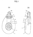
- Fig. 1 including a front view (a) and a side view (b) showing a situation in which a storage bottle and a connector cap are connected
- Fig. 2 is a view showing a situation in which the connector cap is removed from the storage bottle
- Fig. 3 is a view showing a situation in which a coupling device and a detachably connecting device are connected and a situation in which the coupling device and the detachably connecting device are disconnected
- Fig. 4 is an oblique projection view of the storage bottle
- Fig. 1 including a front view (a) and a side view (b) showing a situation in which a storage bottle and a connector cap are connected, wherein (a) is a front view and (b) is a side view
- Fig. 2 is a view showing a situation in which the connector cap is removed from the storage bottle
- Fig. 3 is a view showing
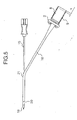
- FIG. 5 is a view showing a situation in which a penetrating needle is inserted through a penetrating needle insert port of the catheter
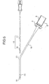
- Fig. 6 is a view showing a situation in which the penetrating needle is drawn out through the penetrating needle insert port of the catheter
- Fig. 7 is a view showing a situation in which the storage bottle is connected to the catheter
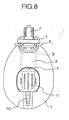
- Fig. 8 is a view showing another embodiment of the invention.
- Fig. 9 is a view showing a situation in which an adapter with a connector is connected to the catheter
- Fig. 10 is a view showing other elements of the invention usable in Seldinger method.
- the storage bottle (1) has an inlet port (26), an outlet port (3) and a discharge port (4), and may have a scale for measuring an amount of discharged liquid on a side surface thereof if necessary.
- the inlet port (26) receives gas and liquid pooling in a chest cavity to be collected through a catheter into the storage bottle (1).
- the outlet port (3) discharges the stored liquid, and has preferably an opening area sufficient for exchanging the liquid to be discharged and an external air only through the outlet port (3) because the storage bottle (1) has no air relief root to form a closed system.
- a detachably connecting device (5) for a connector cap (2) is formed integrally on the outlet port (3), and may be a mechanism in which a coupling device (12) of the connector cap (2) is pressed upward to release a fitting (for example, a snap fitting) with the connecting device (5) by pressing left and right release levers (6) toward each other to be deformed as shown in Fig. 3, while the structure of the detachably connecting device (5) is not limited to this embodiment.
- a material of the detachably connecting device (5) may be hard vinyl chloride, ABS resin or the like for bearing a plurality of stress applying times.
- the storage bottle (1) is preferably compact for improving a portability and a flat container of aspect ratio 20-60% suitable for fitting onto a body surface, and is produced through a blow molding advantageous for producing cost.
- a product through the blow molding for the storage bottle (1) will be explained in detail hereafter, it is important that a thickness of a flat cross section is made as' constant as possible over the whole thereof so that the storage bottle (1) bears a pumping operation (recover in shape in response to a separation from a hand after being compressed) and a flash is prevented to the utmost from being formed on a mating face of the blow mold during the molding so that a durability thereof on the pumping operation is kept.
- a parison having a relatively small diameter with respect to a traverse width of the product of molding is used to prevent the flash from being formed, but for the flat product of molding, a small diameter direction of the flat cross section thereof is set firstly in the mold to restrain an expansion of the resin so that the product of molding has a small thickness in a large diameter direction. Therefore, the parison has a difference in thickness and a large thickness side of the parison having the difference in thickness is arranged in a longitudinal direction of the flat shape of the storage bottle so that the thickness is made constant.
- the material of the storage bottle (1) is preferably a plastic or rubber to obtain a transparency for visibility of a movement of the check valve and a condition of the discharged liquid and an elasticity for the pumping.
- the check valve B (11) has a flat tube shape of soft material such as the plastic and the rubber, and a front end at which inner surfaces thereof contact each other tightly in such a manner that a gas flow discharged from the body can open the contact area to be discharged but prevent a reverse direction flow.
- the connector cap (2) is detachably connectable to the outlet port (3) of the storage bottle (1), and has the coupling device (12) at a fitting portion thereof to form a pair with, for example, the outlet port (3) as described above so that a hermetic sealing is kept when being connected, while a preferable embodiment thereof has a packing therein to keep securely the hermetic sealing.
- the check valve A (8) openable toward the storage bottle (1) is. mounted on the connector cap (2), and a connector A (7) connectable to the catheter (18) retained in the patient is mounted on an upper portion of the connector cap (2).
- a protect cover (9) openable at a forward end side is mounted on an outside of the check valve A (8). Therefore, the check valve A (8) needs to be embedded entirely in the protect cover (9), and a front end position (A dimension in Fig. 1) is preferably lowered by not less than 5 mm.
- the check valve A (8) has the same structure as the above described check valve B (11), wherein the protect cover (9) is preferably made of hard material such as plastic, glass or the' like to obtain the transparency for the visibility of the motion of the check valve A (8) and the protect of the check valve A (8).
- the storage bottle is carried by the patient as a general use condition, a bottom surface on Fig. 1 becomes an lower surface when the patient stands up, and a back surface becomes the lower surface when the patient lies.
- the arrangement is determined from the outer dimension of the storage bottle (1) and an anticipated amount of the discharged liquid in such a manner that the contact is prevented at each of the case where the bottom surface on Fig. 1 is the lower surface and the case where the back surface is the lower surface when the anticipated amount of the discharged liquid is stored.
- the distance (B dimension in Fig. 1) between the storage bottle (1) and the protect cover (9) is preferably made not more than 5 mm.
- various carrier means are incorporated, for example, a carrier clip mounted integrally or detachably on the upper portion of the storage bottle (1) or the connector cap (2), or an adhesive tape or the like attached to the back surface of the storage bottle (1) are usable in consideration of cost and operationality.
- a connector B (10) for being coupled to a connection tube of the suction source for temporary low pressure continuous suction is mounted on a front end of the check valve B (11) of the discharge port (4) as shown in Fig. 8, or in which the connector cap (2) is detachably connectable to the adapter (14) with the connector B (10) through the same connecting means as the storage bottle (1) is preferable.
- Fig. 5 shows that the penetrating needle (15) is inserted from the penetrating needle insert port (21) of the catheter (18), and Fig. 6 shows that the penetrating needle (15) is drawn out of the penetrating needle insert port (21) of the catheter (18).
- the penetrating needle (15) includes a double needle of an inner needle (16) and an outer tube needle (17) as metallic products of stainless steel or the like, while materials thereof should not be limited specifically.
- a step between the inner needle (16) and the outer tube needle (17) is preferably 0.15-0.50 mm to abut on a front tip (19) of the catheter (18) and prevent the penetrating needle (15) from projecting from the catheter (18). This is caused by that when being less than 0.15-0.50 mm, there is a risk of that the penetrating needle (15) proceeds over the front tip (19) to penetrate the chest at a front of the needle when the penetrating needle (15) and the catheter (18) are inserted into the chest cavity. Further, when being more than 0.5 mm, a diameter of the catheter becomes large to cause a probability of a high damage for the patient. Practically, a dimension of the step is preferably 0.3 mm.
- the catheter (18) has the penetrating needle insert port (21), and the integrally formed or X-ray impermeable front tip (19) is mounted on the front end of the catheter (18) so that the penetrating needle (15) is prevented by the step between the inner needle (16) and the outer tube needle (17) from projecting from the catheter (18).
- at least one side holes (20) opens to discharge efficiently the gas and liquid in the chest cavity, and on the back end of the catheter (18), the connector cap (2) including the check valve A (8) openable to the connecting side for the storage bottle (1) is mounted.
- the penetrating needle insert port (21) is an insert port for inserting the penetrating needle (15) into the catheter (18), and the penetrating needle insert port (21) of a notch shape with a size for receiving the penetrating needle preferably has a dimension and shape for preventing a resistance of the penetrating needle insert port (21) against a withdrawal of the outer tube needle (17) when the catheter (18) is drawn out after the medical,procedure while a length of the notch shape is preferably 1-10 mm. It is practically preferable that a length of the catheter (18) is 250-400 mm, and an outer diameter of the catheter (18) is 1-3 mm.
- a position of the penetrating needle insert port (21) is preferably 30-150 mm when taking a retaining length of the catheter (18) in the chest cavity into consideration.
- a position of the penetrating needle insert port (21) is preferably 30-150 mm when taking a retaining length of the catheter (18) in the chest cavity into consideration.
- a skin on the penetrating portion is sanitized and after local anesthesia, cut shortly in accordance with a thickness of the catheter, and after retaining the catheter in the patient, the connector A (7) is connected to the terminating end of the catheter to complete the setting.
- the catheter (18) integrally including the connector cap (2) and the check valve A (8) to penetrate the penetrating needle (15) is drawn out of the catheter (18), the front end of the catheter (18) is retained at an appropriate position in the chest cavity, and the connector cap (2) is connected to the outlet port (3) of the storage bottle (1) to finish the setting.
- the above methods are usable, but for diverent or child patients, the insertion with the Seldinger method (a catheter inserting method with using a guide wire) is preferable.
- the cannula needle is inserted to penetrate.
- the guide wire (24) is inserted along a cannula envelope (23), and the cannula envelope (23) is drawn out.
- a dilator (25) is inserted along the guide wire (24) to enlarge the penetrating route.
- the catheter (18) is inserted into the chest cavity along the guide wire (24).
- the retaining is finished by drawing out the outer tube needle (17) and the guide wire (24), and the connector cap (2) at the back end of the catheter (18) is connected to the outlet port (3) of the storage bottle (1).
- a compulsory discharge from the chest cavity can be performed by pumping the storage bottle to open and close alternately the check valve A (7) and the check valve 3 (11).
- the discharged liquid such as pleural effusion or the like pools in the storage bottle (1)
- release levers (9) of the detachably connecting device (5) are pressed inward toward each other to be deformed to remove the connector cap (2) so that the discharged liquid is discharged from the outlet port (3).
- the atmospheric air is prevented from proceeding into the chest cavity through the check valve A (8) attached to the connector cap (2).
- the discharge equipment for medical procedure of the invention is more compact particularly for cases of small discharged liquid, in which an manual discharge operation can be performed without additional necessary equipment, and the atmospheric air is prevented by the check valve arranged on the back end of the catheter to open only toward the exterior from proceeding into the chest cavity when the penetrating needle is drawn out, so that it is usable as a' low cost simple equipment.
Landscapes
- Health & Medical Sciences (AREA)
- Heart & Thoracic Surgery (AREA)
- Vascular Medicine (AREA)
- Engineering & Computer Science (AREA)
- Anesthesiology (AREA)
- Biomedical Technology (AREA)
- Hematology (AREA)
- Life Sciences & Earth Sciences (AREA)
- Animal Behavior & Ethology (AREA)
- General Health & Medical Sciences (AREA)
- Public Health (AREA)
- Veterinary Medicine (AREA)
- Pulmonology (AREA)
- External Artificial Organs (AREA)
- Media Introduction/Drainage Providing Device (AREA)
Applications Claiming Priority (3)
| Application Number | Priority Date | Filing Date | Title |
|---|---|---|---|
| JP2001363577A JP3989717B2 (ja) | 2000-12-20 | 2001-11-29 | 医療用排出用具 |
| JP2001363577 | 2001-11-29 | ||
| PCT/JP2002/006056 WO2003045470A1 (fr) | 2001-11-29 | 2002-06-18 | Outil d'evacuation pour soins medicaux |
Publications (3)
| Publication Number | Publication Date |
|---|---|
| EP1449547A1 true EP1449547A1 (fr) | 2004-08-25 |
| EP1449547A4 EP1449547A4 (fr) | 2010-06-23 |
| EP1449547B1 EP1449547B1 (fr) | 2012-11-28 |
Family
ID=19173898
Family Applications (1)
| Application Number | Title | Priority Date | Filing Date |
|---|---|---|---|
| EP02736155A Expired - Lifetime EP1449547B1 (fr) | 2001-11-29 | 2002-06-18 | Outil d'evacuation pour soins medicaux |
Country Status (5)
| Country | Link |
|---|---|
| US (1) | US7144385B2 (fr) |
| EP (1) | EP1449547B1 (fr) |
| KR (1) | KR100818843B1 (fr) |
| CN (1) | CN100408117C (fr) |
| WO (1) | WO2003045470A1 (fr) |
Cited By (2)
| Publication number | Priority date | Publication date | Assignee | Title |
|---|---|---|---|---|
| CN102389591A (zh) * | 2011-08-02 | 2012-03-28 | 常熟市赛爱斯医疗器材有限公司 | 医用半自动引流计量装置 |
| CN106390214A (zh) * | 2016-09-23 | 2017-02-15 | 郑迪熹 | 一种医用的负压瓶配件及使用该配件的负压瓶 |
Families Citing this family (3)
| Publication number | Priority date | Publication date | Assignee | Title |
|---|---|---|---|---|
| US8337475B2 (en) * | 2004-10-12 | 2012-12-25 | C. R. Bard, Inc. | Corporeal drainage system |
| GB0503730D0 (en) * | 2005-02-23 | 2005-03-30 | Medical Device Innovations Ltd | Pneumothorax relief device |
| CN113018593B (zh) * | 2021-03-23 | 2022-08-05 | 西安交通大学医学院第一附属医院 | 一种用于糖尿病治疗的医疗装置 |
Family Cites Families (26)
| Publication number | Priority date | Publication date | Assignee | Title |
|---|---|---|---|---|
| US3225762A (en) * | 1963-10-25 | 1965-12-28 | Yolan R Guttman | Intravenous stylet catheter |
| GB1052614A (fr) * | 1964-06-04 | |||
| US3421504A (en) * | 1966-01-25 | 1969-01-14 | De Lamar J Gibbons | Vacuum receptor |
| SE351785B (fr) * | 1970-02-02 | 1972-12-11 | Astra Meditec Ab | |
| US4141361A (en) * | 1970-02-09 | 1979-02-27 | Snyder Manufacturing Co., Incorporated | Evacuator |
| US3742952A (en) * | 1971-04-28 | 1973-07-03 | Alpha Ind Inc | Surgical suction pump assembly |
| US3800795A (en) * | 1971-06-16 | 1974-04-02 | Sherwood Medical Ind Inc | Urinary drainage collecting device |
| US3875941A (en) * | 1974-04-03 | 1975-04-08 | Medical Dynamics Inc | System for evacuating fluids from the body |
| US3991763A (en) * | 1975-04-17 | 1976-11-16 | Arbrook, Inc. | Surgical evacuator |
| US4392860A (en) * | 1979-01-11 | 1983-07-12 | Howmedica, Inc. | Disposable wound drainage device |
| US4529402A (en) * | 1980-07-08 | 1985-07-16 | Snyder Laboratories, Inc. | Closed wound suction evacuator with rotary valve |
| US4392858A (en) * | 1981-07-16 | 1983-07-12 | Sherwood Medical Company | Wound drainage device |
| US4493701A (en) * | 1982-08-19 | 1985-01-15 | American Hospital Supply Corporation | Wound drainage device of resilient sidewalls with a constant rate of recovery |
| US4578060A (en) * | 1983-07-20 | 1986-03-25 | Howmedica, Inc. | Wound drainage device |
| US4643719A (en) * | 1984-07-19 | 1987-02-17 | Garth Geoffrey C | Manually operable aspirator |
| JPS6190669A (ja) * | 1984-10-11 | 1986-05-08 | 住友ベークライト株式会社 | 医療用排出装置 |
| USD312132S (en) * | 1987-09-16 | 1990-11-13 | Uresil Corporation | Surgical drainage unit |
| JPH02261472A (ja) * | 1989-03-31 | 1990-10-24 | Terumo Corp | 液体吸引具 |
| GB2245833A (en) * | 1990-06-26 | 1992-01-15 | Femcare Ltd | Mucus extractor |
| US5318550A (en) * | 1992-10-02 | 1994-06-07 | Tetra Development Society | Urine collecting apparatus |
| JP2871378B2 (ja) | 1993-03-25 | 1999-03-17 | 株式会社クリニカル・サプライ | 弁体を有するシースイントロデューサ |
| CN1160359A (zh) * | 1994-10-11 | 1997-09-24 | 医药研究有限公司 | 改进的伤口抽液系统 |
| JPH08224313A (ja) * | 1995-02-23 | 1996-09-03 | Unitika Ltd | カテーテル挿入方法 |
| JP2001218830A (ja) * | 1999-08-30 | 2001-08-14 | Sumitomo Bakelite Co Ltd | 体液吸引集液器及びその製造方法 |
| JP4094349B2 (ja) * | 2002-06-17 | 2008-06-04 | 住友ベークライト株式会社 | 医療用排出用具 |
| JP2004229780A (ja) * | 2003-01-29 | 2004-08-19 | Sumitomo Bakelite Co Ltd | 医療用排出用具 |
-
2002
- 2002-06-18 WO PCT/JP2002/006056 patent/WO2003045470A1/fr not_active Ceased
- 2002-06-18 KR KR1020047008105A patent/KR100818843B1/ko not_active Expired - Fee Related
- 2002-06-18 EP EP02736155A patent/EP1449547B1/fr not_active Expired - Lifetime
- 2002-06-18 CN CNB028237234A patent/CN100408117C/zh not_active Expired - Fee Related
- 2002-06-18 US US10/497,214 patent/US7144385B2/en not_active Expired - Fee Related
Cited By (2)
| Publication number | Priority date | Publication date | Assignee | Title |
|---|---|---|---|---|
| CN102389591A (zh) * | 2011-08-02 | 2012-03-28 | 常熟市赛爱斯医疗器材有限公司 | 医用半自动引流计量装置 |
| CN106390214A (zh) * | 2016-09-23 | 2017-02-15 | 郑迪熹 | 一种医用的负压瓶配件及使用该配件的负压瓶 |
Also Published As
| Publication number | Publication date |
|---|---|
| EP1449547B1 (fr) | 2012-11-28 |
| WO2003045470A1 (fr) | 2003-06-05 |
| KR100818843B1 (ko) | 2008-04-01 |
| CN1596133A (zh) | 2005-03-16 |
| US7144385B2 (en) | 2006-12-05 |
| US20050080387A1 (en) | 2005-04-14 |
| KR20040070191A (ko) | 2004-08-06 |
| CN100408117C (zh) | 2008-08-06 |
| EP1449547A4 (fr) | 2010-06-23 |
Similar Documents
| Publication | Publication Date | Title |
|---|---|---|
| EP2034924B1 (fr) | Aspirateur comportant une pointe d'aspiration matelassée | |
| AU2010201476B2 (en) | Fluid Collection Reservoir | |
| ES2302012T3 (es) | Tubo traqueal con canulas interna y externa. | |
| US20250082918A1 (en) | Enteral feeding system, method, and apparatus | |
| US6068477A (en) | Foam-cushioned aspirator | |
| WO2022159333A1 (fr) | Système sous vide pour dégager une colonne verticale de fluide | |
| JPH09509866A (ja) | 真空による創傷の縫合及び/又は吸引による分泌物等の吸い出しのための装置 | |
| US20110196382A1 (en) | Device to assist delivery of fetal head at cesarean section | |
| US20030131853A1 (en) | Oro-pharyngeal airway and gas-assisted injection molding method therefor | |
| US7144385B2 (en) | Discharging implement for medical care | |
| JP6569137B1 (ja) | コネクタを用いたドレナージ装置 | |
| US7238023B1 (en) | Saliva ejector or eductor | |
| US5419776A (en) | Pneumothorax treatment device | |
| KR20170040661A (ko) | 의료용 흡인기 | |
| JP3989717B2 (ja) | 医療用排出用具 | |
| JP4094349B2 (ja) | 医療用排出用具 | |
| CN218944118U (zh) | 一种新型尿管 | |
| CN213466455U (zh) | 一种无导丝型经皮气管切开插管辅助器及插管监测系统 | |
| CN2535057Y (zh) | 一种灌肠器 | |
| HK1152262A (en) | A suction liquid collector for medical use | |
| JP2008517688A (ja) | 頬面歯科用衛生装置、及び使い捨てユニット |
Legal Events
| Date | Code | Title | Description |
|---|---|---|---|
| PUAI | Public reference made under article 153(3) epc to a published international application that has entered the european phase |
Free format text: ORIGINAL CODE: 0009012 |
|
| 17P | Request for examination filed |
Effective date: 20040526 |
|
| AK | Designated contracting states |
Kind code of ref document: A1 Designated state(s): AT BE CH CY DE DK ES FI FR GB GR IE IT LI LU MC NL PT SE TR |
|
| A4 | Supplementary search report drawn up and despatched |
Effective date: 20100526 |
|
| 17Q | First examination report despatched |
Effective date: 20101117 |
|
| GRAP | Despatch of communication of intention to grant a patent |
Free format text: ORIGINAL CODE: EPIDOSNIGR1 |
|
| GRAS | Grant fee paid |
Free format text: ORIGINAL CODE: EPIDOSNIGR3 |
|
| GRAA | (expected) grant |
Free format text: ORIGINAL CODE: 0009210 |
|
| AK | Designated contracting states |
Kind code of ref document: B1 Designated state(s): DE FR GB |
|
| REG | Reference to a national code |
Ref country code: GB Ref legal event code: FG4D |
|
| REG | Reference to a national code |
Ref country code: DE Ref legal event code: R096 Ref document number: 60244123 Country of ref document: DE Effective date: 20130124 |
|
| PLBE | No opposition filed within time limit |
Free format text: ORIGINAL CODE: 0009261 |
|
| STAA | Information on the status of an ep patent application or granted ep patent |
Free format text: STATUS: NO OPPOSITION FILED WITHIN TIME LIMIT |
|
| 26N | No opposition filed |
Effective date: 20130829 |
|
| REG | Reference to a national code |
Ref country code: DE Ref legal event code: R097 Ref document number: 60244123 Country of ref document: DE Effective date: 20130829 |
|
| PGFP | Annual fee paid to national office [announced via postgrant information from national office to epo] |
Ref country code: GB Payment date: 20140618 Year of fee payment: 13 |
|
| PGFP | Annual fee paid to national office [announced via postgrant information from national office to epo] |
Ref country code: DE Payment date: 20140611 Year of fee payment: 13 |
|
| PGFP | Annual fee paid to national office [announced via postgrant information from national office to epo] |
Ref country code: FR Payment date: 20140609 Year of fee payment: 13 |
|
| REG | Reference to a national code |
Ref country code: DE Ref legal event code: R119 Ref document number: 60244123 Country of ref document: DE |
|
| GBPC | Gb: european patent ceased through non-payment of renewal fee |
Effective date: 20150618 |
|
| REG | Reference to a national code |
Ref country code: FR Ref legal event code: ST Effective date: 20160229 |
|
| PG25 | Lapsed in a contracting state [announced via postgrant information from national office to epo] |
Ref country code: DE Free format text: LAPSE BECAUSE OF NON-PAYMENT OF DUE FEES Effective date: 20160101 Ref country code: GB Free format text: LAPSE BECAUSE OF NON-PAYMENT OF DUE FEES Effective date: 20150618 |
|
| PG25 | Lapsed in a contracting state [announced via postgrant information from national office to epo] |
Ref country code: FR Free format text: LAPSE BECAUSE OF NON-PAYMENT OF DUE FEES Effective date: 20150630 |