EP1449563A1 - Ultrasons focalisés à haute intensité appliqués de l'extérieur pour un traitement thérapeutique - Google Patents
Ultrasons focalisés à haute intensité appliqués de l'extérieur pour un traitement thérapeutique Download PDFInfo
- Publication number
- EP1449563A1 EP1449563A1 EP04250856A EP04250856A EP1449563A1 EP 1449563 A1 EP1449563 A1 EP 1449563A1 EP 04250856 A EP04250856 A EP 04250856A EP 04250856 A EP04250856 A EP 04250856A EP 1449563 A1 EP1449563 A1 EP 1449563A1
- Authority
- EP
- European Patent Office
- Prior art keywords
- beacon
- time
- signal
- reversed
- transducer
- Prior art date
- Legal status (The legal status is an assumption and is not a legal conclusion. Google has not performed a legal analysis and makes no representation as to the accuracy of the status listed.)
- Withdrawn
Links
- 238000002604 ultrasonography Methods 0.000 title claims abstract description 118
- 230000001225 therapeutic effect Effects 0.000 title description 11
- 238000011282 treatment Methods 0.000 title description 5
- 238000002560 therapeutic procedure Methods 0.000 claims abstract description 17
- 238000002310 reflectometry Methods 0.000 claims description 13
- 239000004575 stone Substances 0.000 claims description 7
- 239000013078 crystal Substances 0.000 claims description 6
- 239000002961 echo contrast media Substances 0.000 claims description 6
- 238000005286 illumination Methods 0.000 claims description 2
- 238000000034 method Methods 0.000 description 80
- 210000001519 tissue Anatomy 0.000 description 50
- 238000001514 detection method Methods 0.000 description 23
- 230000005540 biological transmission Effects 0.000 description 11
- 238000010586 diagram Methods 0.000 description 8
- 238000003384 imaging method Methods 0.000 description 8
- 206010028980 Neoplasm Diseases 0.000 description 6
- 238000002679 ablation Methods 0.000 description 6
- 238000009826 distribution Methods 0.000 description 6
- 208000000913 Kidney Calculi Diseases 0.000 description 5
- 206010029148 Nephrolithiasis Diseases 0.000 description 5
- 238000001574 biopsy Methods 0.000 description 5
- 238000004364 calculation method Methods 0.000 description 5
- 230000000694 effects Effects 0.000 description 5
- 238000003780 insertion Methods 0.000 description 4
- 230000037431 insertion Effects 0.000 description 4
- 238000001356 surgical procedure Methods 0.000 description 4
- 238000010521 absorption reaction Methods 0.000 description 3
- 230000008859 change Effects 0.000 description 3
- 201000010099 disease Diseases 0.000 description 3
- 208000037265 diseases, disorders, signs and symptoms Diseases 0.000 description 3
- 230000005672 electromagnetic field Effects 0.000 description 3
- 238000002594 fluoroscopy Methods 0.000 description 3
- 210000003492 pulmonary vein Anatomy 0.000 description 3
- 230000001105 regulatory effect Effects 0.000 description 3
- 239000000523 sample Substances 0.000 description 3
- 230000002463 transducing effect Effects 0.000 description 3
- 230000002238 attenuated effect Effects 0.000 description 2
- 230000000740 bleeding effect Effects 0.000 description 2
- 210000004556 brain Anatomy 0.000 description 2
- 201000011510 cancer Diseases 0.000 description 2
- 230000001419 dependent effect Effects 0.000 description 2
- 238000003745 diagnosis Methods 0.000 description 2
- 230000000977 initiatory effect Effects 0.000 description 2
- 230000007170 pathology Effects 0.000 description 2
- 210000002307 prostate Anatomy 0.000 description 2
- 238000012285 ultrasound imaging Methods 0.000 description 2
- 206010003130 Arrhythmia supraventricular Diseases 0.000 description 1
- 241000282465 Canis Species 0.000 description 1
- 206010020843 Hyperthermia Diseases 0.000 description 1
- 208000002847 Surgical Wound Diseases 0.000 description 1
- 230000002411 adverse Effects 0.000 description 1
- 210000003484 anatomy Anatomy 0.000 description 1
- 238000003491 array Methods 0.000 description 1
- 238000010009 beating Methods 0.000 description 1
- 210000000481 breast Anatomy 0.000 description 1
- 239000003795 chemical substances by application Substances 0.000 description 1
- 238000005345 coagulation Methods 0.000 description 1
- 230000015271 coagulation Effects 0.000 description 1
- 238000002591 computed tomography Methods 0.000 description 1
- 238000010276 construction Methods 0.000 description 1
- 239000002872 contrast media Substances 0.000 description 1
- 230000001276 controlling effect Effects 0.000 description 1
- 230000006378 damage Effects 0.000 description 1
- 230000002939 deleterious effect Effects 0.000 description 1
- 238000013461 design Methods 0.000 description 1
- 230000001066 destructive effect Effects 0.000 description 1
- 229940079593 drug Drugs 0.000 description 1
- 239000003814 drug Substances 0.000 description 1
- 238000005516 engineering process Methods 0.000 description 1
- 230000002169 extracardiac Effects 0.000 description 1
- 238000013213 extrapolation Methods 0.000 description 1
- 210000003754 fetus Anatomy 0.000 description 1
- 239000012634 fragment Substances 0.000 description 1
- 230000035876 healing Effects 0.000 description 1
- 238000010438 heat treatment Methods 0.000 description 1
- 230000036031 hyperthermia Effects 0.000 description 1
- 239000007943 implant Substances 0.000 description 1
- 208000014674 injury Diseases 0.000 description 1
- 238000002955 isolation Methods 0.000 description 1
- 230000003902 lesion Effects 0.000 description 1
- 238000002686 lithotriptor Methods 0.000 description 1
- 210000004185 liver Anatomy 0.000 description 1
- 230000004807 localization Effects 0.000 description 1
- 238000012986 modification Methods 0.000 description 1
- 230000004048 modification Effects 0.000 description 1
- 210000004165 myocardium Anatomy 0.000 description 1
- 230000001613 neoplastic effect Effects 0.000 description 1
- 230000001766 physiological effect Effects 0.000 description 1
- 230000008569 process Effects 0.000 description 1
- 230000001737 promoting effect Effects 0.000 description 1
- 230000004044 response Effects 0.000 description 1
- 238000012552 review Methods 0.000 description 1
- 239000007787 solid Substances 0.000 description 1
- 238000010561 standard procedure Methods 0.000 description 1
- 238000011287 therapeutic dose Methods 0.000 description 1
- 230000000451 tissue damage Effects 0.000 description 1
- 231100000827 tissue damage Toxicity 0.000 description 1
- 230000008733 trauma Effects 0.000 description 1
Images



Classifications
-
- A—HUMAN NECESSITIES
- A61—MEDICAL OR VETERINARY SCIENCE; HYGIENE
- A61N—ELECTROTHERAPY; MAGNETOTHERAPY; RADIATION THERAPY; ULTRASOUND THERAPY
- A61N7/00—Ultrasound therapy
- A61N7/02—Localised ultrasound hyperthermia
-
- A—HUMAN NECESSITIES
- A47—FURNITURE; DOMESTIC ARTICLES OR APPLIANCES; COFFEE MILLS; SPICE MILLS; SUCTION CLEANERS IN GENERAL
- A47D—FURNITURE SPECIALLY ADAPTED FOR CHILDREN
- A47D15/00—Accessories for children's furniture, e.g. safety belts or baby-bottle holders
-
- A—HUMAN NECESSITIES
- A47—FURNITURE; DOMESTIC ARTICLES OR APPLIANCES; COFFEE MILLS; SPICE MILLS; SUCTION CLEANERS IN GENERAL
- A47D—FURNITURE SPECIALLY ADAPTED FOR CHILDREN
- A47D9/00—Cradles ; Bassinets
- A47D9/02—Cradles ; Bassinets with rocking mechanisms
-
- A—HUMAN NECESSITIES
- A61—MEDICAL OR VETERINARY SCIENCE; HYGIENE
- A61B—DIAGNOSIS; SURGERY; IDENTIFICATION
- A61B90/00—Instruments, implements or accessories specially adapted for surgery or diagnosis and not covered by any of the groups A61B1/00 - A61B50/00, e.g. for luxation treatment or for protecting wound edges
- A61B90/39—Markers, e.g. radio-opaque or breast lesions markers
- A61B2090/3925—Markers, e.g. radio-opaque or breast lesions markers ultrasonic
-
- A—HUMAN NECESSITIES
- A61—MEDICAL OR VETERINARY SCIENCE; HYGIENE
- A61B—DIAGNOSIS; SURGERY; IDENTIFICATION
- A61B90/00—Instruments, implements or accessories specially adapted for surgery or diagnosis and not covered by any of the groups A61B1/00 - A61B50/00, e.g. for luxation treatment or for protecting wound edges
- A61B90/39—Markers, e.g. radio-opaque or breast lesions markers
- A61B2090/3925—Markers, e.g. radio-opaque or breast lesions markers ultrasonic
- A61B2090/3929—Active markers
-
- A—HUMAN NECESSITIES
- A61—MEDICAL OR VETERINARY SCIENCE; HYGIENE
- A61N—ELECTROTHERAPY; MAGNETOTHERAPY; RADIATION THERAPY; ULTRASOUND THERAPY
- A61N7/00—Ultrasound therapy
- A61N2007/0078—Ultrasound therapy with multiple treatment transducers
Definitions
- the present invention relates generally to use of ultrasound in medical technology applications, and specifically to methods and apparatus for performing therapeutic procedures with high-intensity focused ultrasound (HIFU).
- HIFU high-intensity focused ultrasound
- ultrasound for imaging and diagnosis of disease
- signals are delivered to a patient by an ultrasound transducer which converts electrical signals into ultrasound pulses.
- the ultrasound beam is absorbed, dispersed, and reflected within the patient's body.
- reflected ultrasound energy is analyzed and processed to generate image and/or flow information about anatomical structures within the patient's body.
- Typical examples of such ultrasound usage are imaging the heart, evaluating the growth and condition of an unborn fetus, and measuring the size and condition of a prostate gland.
- Ultrasound when applied at power levels required for imaging, has not been found to have deleterious side effects associated with other forms of radiated energy, such as X-rays, microwaves and other electromagnetic fields. Therefore, ultrasound imaging systems have distinct advantages over other imaging modalities.
- absorbed ultrasound energy is used to change the state of the target area.
- ultrasound energy applied at high power densities can have significant physiological effects on tissues. These effects may result from either thermal or mechanical response of the tissue to the imposition of ultrasound energy.
- Thermal effects include hyperthermia and ablation of tissue.
- the absorption of ultrasound energy at the target area induces a sudden temperature rise, which causes coagulation or ablation of target area cells. Consequently, high intensity focused ultrasound (HIFU) can be used for rapid heating of human tissue to arrest bleeding and to ablate tumors.
- HIFU high intensity focused ultrasound
- Mechanical effects of ultrasound include the breaking up of solid objects, liquefaction of tissues, and cavitation.
- a typical application is the lithotriptor, which uses a large radiating surface external to the body of the patient to focus short bursts of ultrasound energy into the patient, in order to mechanically fragment kidney stones.
- HIFU has been proposed as a therapeutic method for treating pathologies which manifest themselves in a localized manner.
- pathologies include, for example, neoplastic and other diseases of or in the brain, breast, liver and prostate.
- neoplastic and other diseases of or in the brain, breast, liver and prostate Although other surgical procedures have been developed for these diseases, such surgery is often lengthy, complex, and expensive. Additionally, the surgery is often repeated, to ensure that the problems have been completely eliminated.
- HIFU therapy is a relatively simple and minimally-invasive alternative, in which the patient is potentially subjected to less trauma, thus promoting faster healing.
- HIFU In therapeutic applications of ultrasound, it is important that the applied ultrasound energy causes an intended change of state solely at a target area, without adversely affecting other tissue within the patient.
- the effective therapeutic dose must be delivered to the target area while the thermal and mechanical effects in intermediary and surrounding tissue are minimized. Therefore, proper focusing and control of HIFU is one of the primary criteria for successful therapeutic application of ultrasound.
- US Patent 6,007,499 to Martin et al. describes methods for reducing bleeding during surgery and for stemming hemorrhaging.
- HIFU is described as being used to form cauterized tissue regions prior to surgical incision, for example, so as to form a cauterized tissue shell around a tumor to be removed.
- US Patent 5,092,336 to Fink describes a device for localization and focusing of acoustic waves in tissues.
- the invention is based upon a technique known as time-reversed acoustics, which is described in an article by Fink, entitled, “Time-Reversed Acoustics,” Scientific American, November 1999, pp. 91 - 97, which is also incorporated herein by reference.
- a target is enclosed by an array of transducers that delivers an unfocused acoustic beam on a reflective target in a medium, for instance, on a tumor in organic tissue.
- Reflected signals detected by the array of transducers are stored, the distribution in time and the shapes of the echo signals are time-reversed, and the reversed signals are applied to the respective transducers of the array.
- the target constitutes a secondary source, which reflects or scatters a wave beam applied to it.
- the target may, for instance, consist of a kidney stone reflecting a beam received from an array of transducers, or a small tumor impregnated with a contrast agent.
- US Patent 6,161,434 to Fink et al. describes methods to use time-reversed acoustics to search for a faint sound source.
- US Patent 5,428,999 to Fink which is also incorporated herein by reference, describes methods for detecting and locating reflecting targets, ultrasound echographic imaging, and concentrating acoustic energy on a target.
- US Patent 5,590,657 to Cain et al. describes an ultrasound system including a phased array of ultrasound transducers located outside the patient. Methods for refocusing the beam are described.
- US Patent 5,366,490 to Edwards et al. describes a method for applying destructive energy to a target tissue using a catheter.
- PCT Patent Publication WO 97/29699 to Ben-Haim entitled, “Intrabody energy focusing,” describes methods for optimizing irradiation of a target area of the body by using a radiation-sensing probe inserted into the body.
- US Patents 5,807,395 to Mulier et al., and 6,190,382 to Ormsby et at. describe systems for ablating body tissue using radio frequency.
- HIFU high-intensity focused ultrasound
- apparatus for performing therapeutic procedures using HIFU comprises a beacon placed within the body of a patient at or in close proximity to a target location of a procedure.
- the control unit stores the shapes and distributions in time of the signals.
- the control unit reverses the distributions in time and the shapes of the signals and drives each transducer in the array to output its respective reversed signal, such that the generated waveform is accurately focused on the site of the beacon or in a vicinity thereof.
- the time-reversed waveforms are typically amplified, thus enabling a substantial amount of energy to be received within a short period at the target location in the vicinity of the beacon.
- the beacon actively emits ultrasound energy, preferably omnidirectional ultrasound energy.
- the beacon comprises a passive ultrasound reflector.
- the beacon is typically illuminated by a generally unfocused ultrasound signal, generated by some or all of the transducers of the array or by another source external to the body, and the array of transducers subsequently detects the echo of the illuminating signal.
- the beacon preferably is of a known geometry that produces a sharp and distinguishable signature that can be identified by the transducers or the control unit.
- the beacon is characterized by substantially higher reflectivity than the natural reflectivity of the surrounding tissue.
- the beacon comprises a crystal with a predefined resonance frequency and a high Q, whereby the beacon is detected by the transducers when they generate the ultrasound signal at the resonance frequency.
- the beacon comprises a bubble containing an ultrasound contrast agent that reflects a known harmonic of the applied ultrasound signal.
- the transducers or control unit identifies the beacon by detecting the known harmonic of the applied frequency.
- the beacon is temporarily placed in the patient, typically by affixing the beacon to the distal end of a catheter for insertion into the body.
- methods and apparatus are preferably but not necessarily utilized which are described in EP-A-1 321 097 and EP-A-1 321 708.
- methods and apparatus known in the art are used to facilitate the placement of the beacon at a desired site in the body.
- the beacon is implanted in a patient, typically during a biopsy, within or adjacent to tissue of interest. If the biopsy is negative, the beacon is either removed or allowed to remain. If the biopsy is positive (e.g., indicative of a malignant tumor), the beacon is used to help focus HIFU waves utilizing the techniques described herein. Alternatively, the beacon is affixed to an implant which is subsequently implanted in the body.
- the control unit is coupled to the active beacon by leads, typically through a catheter.
- An electrical signal is sent to the active beacon, and the active beacon transduces the energy into ultrasound energy, which is received by the transducers outside of the patient's body.
- the active beacon comprises circuitry which wirelessly receives energy radiated from a remote site, typically located outside the patient's body, and the active beacon transduces the energy into the outputted ultrasound energy.
- the energy received from the remote site comprises ultrasound energy and/or electromagnetic energy.
- the beacon is placed sequentially at a plurality of locations in the patient's body, in close proximity to the structure where the intended therapy is to be performed, preferably at locations generally surrounding the structure.
- the plurality of locations comprises at least four non-coplanar locations.
- more than one beacon is implanted in the patient, at a respective plurality of locations in the patient's body.
- the beacon can be either an active element or a passive reflector illuminated by an ultrasound signal, as described hereinabove.
- each beacon comprises a position sensor, to enable a determination of its location with respect to the target structure to be heated or destroyed.
- other techniques e.g., fluoroscopy
- fluoroscopy are utilized to facilitate the determination of the beacon's position with respect to the structure.
- the beacon When the beacon comprises an active element, the beacon receives an electrical signal, either over leads or wirelessly, and the beacon transduces the energy into ultrasound energy, while the beacon is at each of the locations.
- the waveform from the beacon is detected by each of the transducers and is transformed into electrical signals, and the shapes and relative positions in time of the signals are stored in the control unit.
- the control unit uses techniques of time-reversed acoustics to reverse the distributions in time and the shapes of each of the signals received by each of the transducers from each of the beacon locations.
- the control unit calculates an appropriate transmission signal for each transducer. For each transducer, the control unit uses the known positions of the beacon locations and of the target structure to calculate a transmission signal that is focused on the structure rather than the beacon locations.
- the control unit preferably drives each of the transducers to output its respective calculated time-reversed signal, such that the generated waveform is accurately focused on the structure, with any distortions occurring during transmission through the tissue from the vicinity of the structure to the transducers being generally compensated for by identical but time-reversed distortions on the return path.
- the calculated time-reversed waveforms are amplified in order to deposit substantial quantities of energy in short time periods in the immediate vicinity of the structure.
- the beacon does not need to be inserted into the target structure. Such insertion is often difficult or impossible to perform, such as when the structure is a kidney stone.
- the use of a beacon positioned at the target site raises the accuracy of HIFU therapeutic procedures by increasing the probability that the HIFU waves are focused on the precise location of the targeted tissue, and, additionally, that each external transducer is focused on generally the same location of the target. This is in contrast to other methods, which attempt to focus the HIFU waves on tissue having particular reflective or absorptive characteristics.
- the placement of the beacon enables HIFU to be accurately focused on a moving target, such as on a site in the heart.
- the array of transducers can be adapted to refocus the HIFU at a rapid rate responsive to the ultrasound energy from the moving beacon.
- apparatus for performing a therapeutic procedure using ultrasound including:
- the set of transducers is adapted to be applied to an external surface of the body of the subject.
- each transducer is adapted to configure its time-reversed signal to be reversed in time and shape with respect to a property of the beacon signal detected by that transducer.
- each transducer is adapted to amplify the time-reversed signal prior to outputting the time-reversed signal.
- the beacon is adapted to be implanted at the site.
- the beacon is adapted to be placed in a vicinity of cancerous tissue at the site, and the set of transducers is adapted to output the time-reversed signal so as to destroy the cancerous tissue.
- the beacon is adapted to be placed in a vicinity of non-cancerous tissue at the site, and the set of transducers is adapted to output the time-reversed signal so as to heat the non-cancerous tissue.
- the beacon is adapted to be placed in a vicinity of electrically-malfunctioning tissue at the site, and the set of transducers is adapted to output the time-reversed signal so as to destroy the tissue.
- the beacon is adapted to be placed in a vicinity of a stone at the site, and the set of transducers is adapted to output the time-reversed signal so as to break the stone.
- the one or more transducers include a single ultrasound transducer, and the single ultrasound transducer is adapted to output the time-reversed signal reversed in time with respect to a shape of the beacon signal detected by the single ultrasound transducer.
- the one or more transducers include a plurality of transducers, each adapted to output the time-reversed signal reversed in time with respect to a sequence of detecting the beacon signal at the plurality of transducers.
- each transducer is adapted to regulate a timing parameter of the outputting of the respective time-reversed signal, responsive to a position of the transducer, a position of the beacon, and a position of a target in the body.
- the apparatus includes an instrument having a distal end, which is adapted to be inserted into the body and brought to the site, and the beacon is adapted to be affixed in a vicinity of the distal end of the instrument.
- the instrument includes a catheter.
- the beacon includes a passive element
- the apparatus includes an ultrasound transmitter, adapted to illuminate the beacon with an illuminating ultrasound signal, and each transducer is adapted to detect an echo signal coming from the beacon responsive to illumination by the illuminating signal, and to output the time-reversed signal, reversed in time with respect to a property of the echo signal detected by that transducer.
- the transmitter includes one of the transducers.
- the passive element includes an ultrasound reflector, characterized by higher ultrasound reflectivity than a natural level of ultrasound reflectivity at the site.
- the passive element is of a geometry that produces a distinguishable signature in the echo signal when the element is illuminated by the transmitter, and one or more of the transducers are adapted to detect the signature in the echo signal and to output the time-reversed signal responsive thereto.
- the passive element includes a crystal having a predefined resonance frequency.
- the passive element includes an ultrasound contrast agent that reflects a known harmonic of the illuminating signal, and one or more of the transducers are adapted to detect the known harmonic and to output the time-reversed signal responsive thereto.
- the apparatus includes a control unit, adapted to store the beacon signals received from the beacon by each transducer, and adapted to drive each transducer to output its respective time-reversed signal.
- each transducer is adapted to transform the beacon signals it receives into electrical signals, and to transmit the electrical signals to the control unit.
- the control unit is adapted to drive each transducer to configure its respective time-reversed signal to have a greater amplitude than a corresponding amplitude of the beacon signal received by the respective transducer.
- the beacon includes circuitry to receive energy, and is adapted to transduce the received energy so as to generate the beacon signal.
- the beacon is adapted to configure the beacon signal to include one or more generally omnidirectional pulses.
- the apparatus includes external power circuitry, and a set of one or more wires connecting the external power circuitry to the beacon, and the external power circuitry is adapted to transmit the energy to the beacon through the wires.
- the circuitry is adapted to receive the energy wirelessly.
- the apparatus includes a power transmitter, adapted to be located outside the body, and to wirelessly transmit the energy to the beacon.
- the power transmitter is adapted to wirelessly transmit ultrasound energy to the beacon.
- the power transmitter is adapted to wirelessly transmit electromagnetic energy to the beacon.
- the beacon is adapted to be placed in sequence at a plurality of locations in a vicinity of the site. In an embodiment, the beacon is adapted to be placed at the plurality of locations, such locations including at least four non-coplanar locations.
- each transducer is adapted to detect a respective beacon signal when the beacon is at each respective location, and is adapted to subsequently output the time-reversed signal, responsive to the respective beacon signals from the beacon at each respective location and responsive to a position of a target in a vicinity of the site.
- the beacon includes a location sensor, adapted to generate a respective location signal responsive to a respective location of the beacon, and each transducer is adapted to output the time-reversed signal responsive to the location signals.
- the one or more transducers include a plurality of ultrasound transducers, adapted to output the time-reversed signals responsive to the position of the target and reversed in time with respect to a sequence of detecting, at the plurality of transducers, the beacon signal when the beacon is at each location.
- each transducer is adapted to regulate a timing parameter of the outputting of the time-reversed signal, responsive to a position of the transducer, a position of the beacon when the beacon is at each location, and the position of the target.
- the beacon includes a plurality of beacons, each adapted to be implanted at a different location in a vicinity of the site.
- the plurality of beacons includes four beacons, adapted to be placed at different locations near the site, such locations including at least four non-coplanar locations.
- each transducer is adapted to detect a beacon signal coming from each beacon, and, subsequently, to output the time-reversed signal responsive to the beacon signals and a position of a target in a vicinity of the site.
- each of the beacons includes a respective location sensor, adapted to generate a respective location signal responsive to a respective location of the respective beacon, and each transducer is adapted to output the time-reversed signal responsive to the location signals.
- the one or more transducers include a plurality of ultrasound transducers adapted to output respective time-reversed signals, responsive to the position of the target and reversed in time with respect to a sequence of detecting, at the plurality of transducers, the beacon signal coming from each beacon.
- each transducer is adapted to regulate a timing parameter of the outputting of the time-reversed signal, responsive to a position of the transducer, a location of each beacon, and the position of the target.
- a method for performing a therapeutic procedure using ultrasound including:
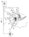
- Fig. 1 is a simplified pictorial illustration showing a HIFU therapeutic system 18 applied to a patient, in accordance with a preferred embodiment of the present invention.
- HIFU therapeutic system 18 comprises a plurality of ultrasound transducers 30 which are coupled to a control unit 50.
- Transducers 30 are preferably applied in an array to a surface 22 of the patient's body such as the skin.
- the transducers may be of a design known in the art, and typically include piezoelectric elements.
- Transducers 30 detect ultrasound energy from a beacon 20, and deliver electrical signals, responsive thereto, to control unit 50.
- Beacon 20 is placed in the patient's body within or in close proximity to a site at which the intended therapy is to be performed.
- Fig. 1 shows beacon 20 placed at or in the vicinity of a structure 40 including a tumor within the brain.
- structure 40 may include non-cancerous tissue, electrically-malfunctioning tissue, a calculus, or other structures which are amenable for treatment or ablation by the application of ultrasound.
- beacon 20 is temporarily placed in the patient, typically by affixing the beacon to the distal end of a guide tube 32, such as a catheter or a probe, for insertion into the body.
- a guide tube 32 such as a catheter or a probe
- methods and apparatus are preferably utilized which are described in one or both of the above-cited EP-A-1 321 097 and EP-A-1 321 708.
- other methods known in the art, such as fluoroscopy are appropriate for use with this embodiment.
- Fig. 2 is a simplified pictorial illustration showing a HIFU therapeutic system 19 applied to a patient, in accordance with a preferred embodiment of the present invention.
- System 19 is similar in many respects to system 18, with differences as elaborated hereinbelow.
- beacon 20 is implanted within tissue of interest in the body, typically during a biopsy. If the biopsy is negative, the beacon is either removed or allowed to remain.
- control unit 50 drives power circuitry 62 (Fig. 1) to transmit power to beacon 20 through wires 34, which typically comprise leads passed through guide tube 32.
- control unit 50 drives a power transmitter 60 (Fig. 2), typically located outside the patient's body, to wirelessly transmit power to beacon 20, in which case beacon 20 comprises circuitry which receives the radiated energy.
- the energy radiated from power transmitter 60 includes ultrasound and/or electromagnetic energy.
- one or more of transducers 30 are adapted to wirelessly transmit power to beacon 20, preferably in the form of ultrasound energy; in this embodiment, power transmitter 60 is not used.
- beacon 20 is affixed to guide tube 32 and receives power wirelessly from power transmitter 60; in this embodiment, power circuitry 62 and power wires 34 are not used.
- beacon 20 transduces the received energy (whether received wirelessly or over wires 34) into outputted ultrasound energy, typically as one or more omnidirectional pulses.
- beacon 20 comprises a passive reflector that is illuminated by an ultrasound signal, generated by a transmitter such as one or more of transducers 30, and transducers 30 detect the echo of the illuminating signal.
- beacon 20 can be attached to guide tube 32 (shown in Fig. 1) or implanted in the patient (as shown in Fig. 2).
- beacon 20 preferably is of a geometry that produces a sharp and distinguishable signature that can be identified by transducers 30 or control unit 50.
- beacon 20 is characterized by substantially higher reflectivity than the natural reflectivity of structure 40 and/or the surrounding tissue.
- beacon 20 comprises a crystal with a predefined resonance frequency and a high Q so that beacon 20 is only detected by transducers 30 when they generate the illuminating ultrasound signal at a certain frequency.
- beacon 20 comprises a bubble containing an ultrasound contrast agent that reflects a known harmonic of the applied ultrasound signal.
- transducers 30 or control unit 50 identifies beacon 20 by detecting the known harmonic of the applied frequency.
- the waveform from beacon 20 is detected by each of transducers 30, typically after a delay which is dependent upon (a) the distance between the beacon and each individual transducer 30 in the array, and (b) the transmission properties of the tissue through which the ultrasound energy passes prior to being received by each individual transducer 30.
- the shape of the waveform received at each individual transducer 30 is typically different from that received at other transducers because of the variation in absorption properties in the various intermediate tissues.
- the waveform received by transducers 30 is transformed into electrical signals, and the shapes and relative positions in time of the signals are stored in control unit 50.
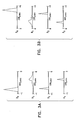
- Fig. 3A is a timing diagram showing one example of electrical signals conveyed from transducers 30 to control unit 50, responsive to the ultrasound signals received by the transducers from beacon 20.
- transducer R 1 is shown conveying a heavily-attenuated signal approximately 40 microseconds after transducer R 4 conveys a less attenuated signal.
- Transducers R 2 and R 3 are shown conveying signals of different delay and shape.
- control unit 50 upon receipt of the electrical signals from transducers 30, control unit 50 uses techniques of time-reversed acoustics (e.g., those described in the above-cited patents or article by Fink, all of which are incorcorporated herein by reference) to reverse the distributions in time and the shapes of the signals.
- time-reversed acoustics e.g., those described in the above-cited patents or article by Fink, all of which are incorcorporated herein by reference
- Fig. 3B is an example timing diagram showing reversed electrical signals generated by control unit 50, corresponding to the example signals shown in Fig. 3A, in accordance with a preferred embodiment of the present invention.
- control unit 50 drives each of transducers 30 to output its respective reversed signal, such that the generated waveform is accurately focused on the site of beacon 20, with any distortions occurring during transmission through the tissue from beacon 20 to transducers 30 being compensated for by generally identical but time-reversed distortions on the return path.
- the time-reversed waveforms are amplified in order to deposit substantial quantities of energy in short time periods in the immediate vicinity of the beacon.
- control unit 50 reverses the sequence of ultrasound signals received at transducers 30 in order to generate the sequence of time-reversed waveforms generated by the transducers.
- the control unit may be adapted to drive the respective transducers to output square pulses at times 150, 130, 105, and 100 microseconds. These pulses converge at the site of the beacon generally simultaneously, thus resulting in a significant deposit of energy at the site in a short time period.
- beacon 20 is placed sequentially at a plurality of locations in the patient's body in close proximity to structure 40 (where the intended therapy is to be performed), preferably at locations generally surrounding and in close proximity to the structure, and preferably not within the structure itself.
- the plurality of locations comprise at least four non-coplanar locations.
- beacon 20 may be implanted in the patient, at a respective plurality of locations in the patient's body.
- beacon 20 can be either an active element or a passive reflector illuminated by an ultrasound signal, as described hereinabove.
- Each beacon can have a different known geometry that produces a sharp and distinguished signature that can be identified by transducers 30 or control unit 50.
- each beacon comprises a crystal with a different respective predefined resonance frequency and a high Q, so that each beacon is detected by transducers 30 when they generate the ultrasound signal at the resonance frequency that is defined for each beacon.
- each beacon comprises a bubble containing an ultrasound contrast agent that reflects a different known harmonic of the applied ultrasound signal.
- transducers 30 or control unit 50 identifies beacon 20 by detecting the known harmonic of the applied frequency, which is different for each beacon.
- all the beacons are of substantially identical construction, and control unit 50 uses algorithms, and optionally position data, to distinguish between the different beacons.
- the beacons are characterized by substantially higher reflectivity than the natural reflectivity of structure 40.
- control unit 50 drives power circuitry 62, power transmitter 60, or one or more of transducers 30 to transmit power to beacon 20, as described hereinabove, while beacon 20 is at each of the locations.
- Beacon 20 transduces the received energy into outputted ultrasound energy, typically as one or more omnidirectional pulses.
- beacon 20 comprises an active or passive element
- the waveform from beacon 20 is detected by each of transducers 30, typically after a delay dependent upon factors described hereinabove.
- the shape of the waveform received at each individual transducer 30 is typically different from that received at other transducers because of the variation in absorption properties in the various intermediate tissues.
- the waveform received by transducers 30 is transformed into electrical signals, and the shapes and relative positions in time of the signals are stored in control unit 50.
- Fig. 4A is a two-dimensional schematic diagram illustrating a simplified example of the placement of one or more beacons 20 at a plurality of locations in the subject, in accordance with a preferred embodiment of the present invention.
- Transducer R 1 is one of transducers 30, and L 1 , L 2 and L 3 are three locations whereat beacon 20 or a plurality of beacons 20 have been placed surrounding structure 40.
- Fig. 4B is a timing diagram showing electrical signals conveyed from transducer R 1 in the example of Fig. 4A to control unit 50, responsive to the ultrasound signals received by transducer R 1 from beacon or beacons 20 while at locations L 1 , L 2 and L 3 .
- transducer R 1 is shown conveying similarly shaped signals for each of the beacon locations, differing mainly in timing, responsive to the different distances between each of the locations and transducer R 1 .
- the peak of the waveform in signal L 2 is shown as occurring later than the peaks of the waveforms L 1 and L 3 .
- control unit 50 Upon receipt of the electrical signals from transducers 30 for each of the beacon locations, control unit 50 uses techniques of time-reversed acoustics (e.g., such as those described in the above-cited patents or article by Fink) to reverse the distributions in time and the shapes of each of the signals received by each of the transducers from each of the beacon locations.
- Fig. 4C is an example timing diagram showing reversed electrical signals (L 1 , L 2 and L 3 ) determined by control unit 50, corresponding to the example signals shown in Fig. 4B, and a calculated electrical signal (L C ) generated by control unit 50, in accordance with a preferred embodiment of the present invention.
- control unit 50 calculates an appropriate transmission signal for each transducer, typically as follows. For each transducer 30, control unit 50 utilizes the known positions of the beacon locations and of structure 40 to calculate a transmission signal that is focused on structure 40 rather than the beacon locations. If structure 40 is within the shape defined by the beacon locations, the calculation performed preferably includes interpolation of the signals from each of the beacon locations; otherwise, the calculation typically includes extrapolation. Because the tissue in the vicinity of structure 40 is typically substantially homogenous, the calculation generally produces a signal primarily shifted in time, rather than with modified shape, relative to the signals from each of the beacon locations.
- transducer 30 in Fig. 4A would apply the lower three signals shown in Fig. 4C, in sequence and in coordination with the other transducers 30 (Fig. 1).
- the example calculated waveform L C in Fig. 4C peaks between the peaks of L 1 and L 2 , slightly closer to L 1 , reflecting the relative distances of L 1 and L 2 from transducer R 1 , as shown in Fig. 4A.
- the control unit performs the above-described calculations prior to time-reversing the signals, and subsequently time-reverses the calculated transmission signal.
- Control unit 50 preferably drives each of transducers 50 to output its respective calculated reversed signal, such that the generated waveform is accurately focused on structure 40, with any distortions occurring during transmission through the tissue from the vicinity of structure 40 to transducers 30 being compensated for by generally identical but time-reversed distortions on the return path.
- the calculated time-reversed waveforms are amplified in order to deposit substantial quantities of energy in short time periods in the immediate vicinity of structure 40.
- control unit 50 performs the above-described calculations individually for each of the sub-volumes, and drives the transducers to focus their waveforms on each sub-volume individually.
- beacon 20 does not need to be inserted into structure 40. Such insertion is often difficult or impossible to perform, such as when the structure is a kidney stone.
- the position of structure 40 is not necessarily directly determined or explicitly known to control unit 50 using standard methods such as a CT scan. Rather, the locations at which beacon or beacons 20 have been placed by a physician during a medical procedure are used to delineate boundaries of a three-dimensional volume which generally surrounds structure 40.
- the three-dimensional shape of structure 40 is generally determined using this procedure, and, subsequently, techniques described herein are applied to focus the time-reversed ultrasound signal from the various transducers 30 onto structure 40.
- Fig. 5 is a schematic illustration of a HIFU therapeutic system 21, in accordance with a preferred embodiment of the present invention. Except for differences as described, system 21 preferably operates using techniques and apparatus similar to those described hereinabove.
- each ultrasound transducer 30 preferably comprises a position sensor 42, which generates a position signal indicative of the position of the respective transducer.
- the position sensor 42 in one embodiment according to the present invention is an electromagnetic field responsive position sensor responsive to electromagnetic fields generated by magnetic field generators/radiators as part of a location system for determining the location, i.e. position and orientation of the position sensor 42.
- the location includes up to six directions and orientations such as (X, Y, Z directions and Pitch, Yaw and Roll orientations).
- the location system including the position sensor 42 and magnetic field generators (radiators) are described in greater detail in U.S. Patent Application Serial No. 08/793,371 entitled "Medical Diagnosis, Treatment and Imaging Systems", filed May 14, 1997, the disclosure of which is incorporated herein by reference.
- a beacon package 44 comprising beacon 20, preferably also comprises a position sensor 42, which generally continuously transmits a signal indicative of the position of the beacon.
- the position of beacon 20 is determined using other methods (e.g., fluoroscopy), and the positions of the ultrasound transducers are determined using other methods (e.g., by rigid attachment to a fixed frame).
- the position of structure 40 is determined using imaging techniques known in the art.
- control unit 50 Responsive to determining the generally-fixed positions of ultrasound transducers 30, beacon 20, and structure 40, control unit 50 preferably calculates a time offset to be applied to the initiation of transmission of the time-reversed signal from each transducer.
- a plurality of beacons 20 are typically not used, and, additionally, beacon 20 is typically not moved to a number of locations in the vicinity of structure 40.
- the time offsets are preferably determined responsive to the fixed position of the beacon with respect to the transducers and the structure. For example, as shown illustratively in Fig. 5, transducer R 1 , beacon 20, structure 40, and transducer R 3 generally lie at respective points along a line.
- the time-reversed signal emitted by transducer R 3 is initiated at a time t + dt, where initiation of transmission of the time-reversed signal from transducer R 1 occurs at time t, such that the time-reversed signals from transducers R 1 and R 3 will strike structure 40 at generally the same time.
- dt is selected based on the relative locations of the transducers, beacon 20, and structure 40, as well as the speed of sound in tissue.
- the ultrasound energy emitted by each of the transducers is preferably focused on structure 40 in whole or in part, or, as appropriate, in sequence on sub-volumes of the structure (e.g., by scanning the focus of the time-reversed signals onto each sub-volume).
- control unit 50 varies the magnitude of the ultrasound energy coming from beacon 20 and/or transducers 30, responsive to various factors and conditions during a procedure.
- the process of focusing the transducer-generated HIFU may be iterative (e.g., as described in the above-cited patents to Fink or Fink et al. or article by Fink).
Landscapes
- Health & Medical Sciences (AREA)
- General Health & Medical Sciences (AREA)
- Animal Behavior & Ethology (AREA)
- Nuclear Medicine, Radiotherapy & Molecular Imaging (AREA)
- Radiology & Medical Imaging (AREA)
- Life Sciences & Earth Sciences (AREA)
- Biomedical Technology (AREA)
- Engineering & Computer Science (AREA)
- Public Health (AREA)
- Veterinary Medicine (AREA)
- Pediatric Medicine (AREA)
- Surgical Instruments (AREA)
- Ultra Sonic Daignosis Equipment (AREA)
Applications Claiming Priority (2)
| Application Number | Priority Date | Filing Date | Title |
|---|---|---|---|
| US370381 | 2003-02-19 | ||
| US10/370,381 US20040162507A1 (en) | 2003-02-19 | 2003-02-19 | Externally-applied high intensity focused ultrasound (HIFU) for therapeutic treatment |
Publications (1)
| Publication Number | Publication Date |
|---|---|
| EP1449563A1 true EP1449563A1 (fr) | 2004-08-25 |
Family
ID=32736442
Family Applications (1)
| Application Number | Title | Priority Date | Filing Date |
|---|---|---|---|
| EP04250856A Withdrawn EP1449563A1 (fr) | 2003-02-19 | 2004-02-18 | Ultrasons focalisés à haute intensité appliqués de l'extérieur pour un traitement thérapeutique |
Country Status (7)
| Country | Link |
|---|---|
| US (1) | US20040162507A1 (fr) |
| EP (1) | EP1449563A1 (fr) |
| JP (1) | JP2004249106A (fr) |
| KR (1) | KR20040074618A (fr) |
| AU (1) | AU2004200533A1 (fr) |
| CA (1) | CA2458053A1 (fr) |
| IL (1) | IL160316A0 (fr) |
Cited By (9)
| Publication number | Priority date | Publication date | Assignee | Title |
|---|---|---|---|---|
| WO2007013895A2 (fr) | 2005-04-12 | 2007-02-01 | Prorhythm, Inc. | Procede, appareil et sonde de production d'ultrasons |
| WO2007073551A1 (fr) * | 2005-12-22 | 2007-06-28 | Boston Scientific Scimed, Inc. | Dispositif et procede pour determiner l'emplacement d'une ouverture vasculaire prealablement a l'application d'une energie hifu pour fermer l'ouverture |
| WO2007047993A3 (fr) * | 2005-10-20 | 2007-08-30 | Therus Corp | Systeme et methodes d'occlusion d'ouverture vasculaire |
| WO2007136335A1 (fr) * | 2006-05-23 | 2007-11-29 | Electromagnetic Consulting Ab | Procédé et système en rapport avec l'hyperthermie |
| EP1955733A1 (fr) * | 2007-02-06 | 2008-08-13 | Siemens Schweiz AG | Dispositif de localisation spatiale d'une partie du corps mobile |
| RU2366475C2 (ru) * | 2005-01-31 | 2009-09-10 | Чонгцинг Хайфу(Хифу)Текнолоджи Ко., Лтд | Терапевтическая система на основе сфокусированного ультразвука |
| WO2010004372A1 (fr) * | 2008-07-10 | 2010-01-14 | Centre National De La Recherche Scientifique - Cnrs | Procédé de focalisation d’un champ d’onde ultrasonore |
| US8622937B2 (en) | 1999-11-26 | 2014-01-07 | Kona Medical, Inc. | Controlled high efficiency lesion formation using high intensity ultrasound |
| WO2014207665A3 (fr) * | 2013-06-28 | 2015-04-09 | Koninklijke Philips N.V. | Positionnement de transducteur et enregistrement pour sonothrombolyse guidée par l'image |
Families Citing this family (61)
| Publication number | Priority date | Publication date | Assignee | Title |
|---|---|---|---|---|
| US8241274B2 (en) * | 2000-01-19 | 2012-08-14 | Medtronic, Inc. | Method for guiding a medical device |
| US7201749B2 (en) * | 2003-02-19 | 2007-04-10 | Biosense, Inc. | Externally-applied high intensity focused ultrasound (HIFU) for pulmonary vein isolation |
| CN101090670B (zh) * | 2004-08-17 | 2010-05-26 | 特赫尼恩研究与发展基金有限公司 | 超声成像引导的组织破坏系统及方法 |
| US7553284B2 (en) * | 2005-02-02 | 2009-06-30 | Vaitekunas Jeffrey J | Focused ultrasound for pain reduction |
| EP1904179A2 (fr) * | 2005-06-07 | 2008-04-02 | Koninklijke Philips Electronics N.V. | Procede et appareil d'apport de medicaments par ultrasons et therapie thermique avec fluides convertible par phase |
| US9861836B2 (en) * | 2005-06-16 | 2018-01-09 | Biosense Webster, Inc. | Less invasive methods for ablation of fat pads |
| US8649875B2 (en) * | 2005-09-10 | 2014-02-11 | Artann Laboratories Inc. | Systems for remote generation of electrical signal in tissue based on time-reversal acoustics |
| US7713200B1 (en) | 2005-09-10 | 2010-05-11 | Sarvazyan Armen P | Wireless beacon for time-reversal acoustics, method of use and instrument containing thereof |
| US8649876B2 (en) * | 2005-09-10 | 2014-02-11 | Artann Laboratories Inc. | Leadless system for deep brain stimulation using time reversal acoustics |
| US10219815B2 (en) | 2005-09-22 | 2019-03-05 | The Regents Of The University Of Michigan | Histotripsy for thrombolysis |
| US8357095B2 (en) * | 2005-10-20 | 2013-01-22 | The General Hospital Corporation | Non-invasive treatment of fascia |
| JP5150125B2 (ja) * | 2007-03-30 | 2013-02-20 | 日本電気株式会社 | 探知装置及び探知用プログラム並びに探知方法 |
| US7909767B2 (en) * | 2007-05-16 | 2011-03-22 | General Electric Company | Method for minimizing tracking system interference |
| US20080287805A1 (en) * | 2007-05-16 | 2008-11-20 | General Electric Company | System and method to guide an instrument through an imaged subject |
| US8057397B2 (en) * | 2007-05-16 | 2011-11-15 | General Electric Company | Navigation and imaging system sychronized with respiratory and/or cardiac activity |
| US8527032B2 (en) * | 2007-05-16 | 2013-09-03 | General Electric Company | Imaging system and method of delivery of an instrument to an imaged subject |
| US8790262B2 (en) * | 2007-05-16 | 2014-07-29 | General Electric Company | Method for implementing an imaging and navigation system |
| US7940972B2 (en) * | 2007-05-16 | 2011-05-10 | General Electric Company | System and method of extended field of view image acquisition of an imaged subject |
| US8989842B2 (en) | 2007-05-16 | 2015-03-24 | General Electric Company | System and method to register a tracking system with intracardiac echocardiography (ICE) imaging system |
| US20080287783A1 (en) * | 2007-05-16 | 2008-11-20 | General Electric Company | System and method of tracking delivery of an imaging probe |
| US9055883B2 (en) * | 2007-05-16 | 2015-06-16 | General Electric Company | Surgical navigation system with a trackable ultrasound catheter |
| US8213693B1 (en) | 2007-05-16 | 2012-07-03 | General Electric Company | System and method to track and navigate a tool through an imaged subject |
| US8428690B2 (en) | 2007-05-16 | 2013-04-23 | General Electric Company | Intracardiac echocardiography image reconstruction in combination with position tracking system |
| US8364242B2 (en) | 2007-05-17 | 2013-01-29 | General Electric Company | System and method of combining ultrasound image acquisition with fluoroscopic image acquisition |
| US20090082703A1 (en) * | 2007-09-26 | 2009-03-26 | Robert Muratore | Method and apparatus for the treatment of tendon abnormalities |
| US20090216128A1 (en) * | 2008-02-25 | 2009-08-27 | Artann Laboratories, Inc. | Broadband Ultrasonic Probe |
| US8545405B2 (en) * | 2008-04-23 | 2013-10-01 | Therataxis, Llc | Device, methods, and control for sonic guidance of molecules and other material utilizing time-reversal acoustics |
| US7587291B1 (en) | 2008-05-05 | 2009-09-08 | Artann Laboratories | Focusing of broadband acoustic signals using time-reversed acoustics |
| WO2010096495A1 (fr) * | 2009-02-18 | 2010-08-26 | The Regents Of The University Of California | Dispositifs, procédés et commande pour le guidage sonore de molécules et d'autres matériaux au moyen de l'acoustique à retournement temporel |
| US8617150B2 (en) | 2010-05-14 | 2013-12-31 | Liat Tsoref | Reflectance-facilitated ultrasound treatment |
| US9242122B2 (en) | 2010-05-14 | 2016-01-26 | Liat Tsoref | Reflectance-facilitated ultrasound treatment and monitoring |
| US8956346B2 (en) | 2010-05-14 | 2015-02-17 | Rainbow Medical, Ltd. | Reflectance-facilitated ultrasound treatment and monitoring |
| JP5175328B2 (ja) * | 2010-12-22 | 2013-04-03 | 学校法人慈恵大学 | 医療用超音波振動子 |
| WO2012120495A2 (fr) * | 2011-03-04 | 2012-09-13 | Rainbow Medical Ltd. | Traitement et surveillance des tissus par application d'énergie |
| KR101252029B1 (ko) * | 2011-05-17 | 2013-04-10 | 주식회사 하이로닉 | 정밀 시술이 가능한 고강도 집속 초음파 생성 장치 |
| DK2736468T3 (en) | 2011-07-27 | 2016-08-01 | Univ Pierre Et Marie Curie Paris 6 | Device for treatment of the sensory capabilities of a person |
| US9101333B2 (en) | 2011-11-14 | 2015-08-11 | Biosense Webster (Israel) Ltd. | Integrative atrial fibrillation ablation |
| US9707414B2 (en) | 2012-02-14 | 2017-07-18 | Rainbow Medical Ltd. | Reflectance-facilitated ultrasound treatment and monitoring |
| WO2014068577A2 (fr) | 2012-11-05 | 2014-05-08 | Rainbow Medical Ltd. | Ablation commandée de tissu |
| US9770593B2 (en) | 2012-11-05 | 2017-09-26 | Pythagoras Medical Ltd. | Patient selection using a transluminally-applied electric current |
| WO2015003154A1 (fr) | 2013-07-03 | 2015-01-08 | Histosonics, Inc. | Limiteur de bras d'articulation pour un système de traitement par cavitation aux ultrasons |
| WO2015027164A1 (fr) | 2013-08-22 | 2015-02-26 | The Regents Of The University Of Michigan | Histotripsie au moyen d'impulsions d'ultrasons très courtes |
| EP2886159A1 (fr) * | 2013-12-23 | 2015-06-24 | Theraclion SA | Procédé pour faire fonctionner un dispositif de traitement d'un tissu et dispositif de traitement d'un tissu |
| EP3139853B1 (fr) | 2014-05-07 | 2018-12-19 | Pythagoras Medical Ltd. | Dispositif d'ablation de tissu commandées |
| WO2016097867A2 (fr) | 2014-12-19 | 2016-06-23 | Université Pierre Et Marie Curie (Paris 6) | Dispositif de traitement implantable produisant des ultrasons pour le traitement du cerveau, appareil comprenant un tel dispositif et procédé mettant en œuvre un tel dispositif |
| US10383685B2 (en) | 2015-05-07 | 2019-08-20 | Pythagoras Medical Ltd. | Techniques for use with nerve tissue |
| WO2016210133A1 (fr) * | 2015-06-24 | 2016-12-29 | The Regents Of The Universtiy Of Michigan | Systèmes et procédés de thérapie par histotripsie pour le traitement de tissu cérébral |
| WO2017153798A1 (fr) | 2016-03-11 | 2017-09-14 | Université Pierre Et Marie Curie (Paris 6) | Dispositif de traitement implantable générant des ultrasons pour le traitement de la moelle épinière et/ou du nerf rachidien, appareil comprenant un tel dispositif et procédé |
| CA3017916C (fr) | 2016-03-11 | 2023-11-07 | Sorbonne Universite | Dispositif de traitement externe generant des ultrasons pour le traitement de la moelle epiniere et des nerfs rachidiens, appareil comprenant un tel dispositif et methode mettant en oeuvre un tel dispositif |
| EP3457975A2 (fr) | 2016-05-18 | 2019-03-27 | Pythagoras Medical Ltd. | Cathéter hélicoïdal |
| CA3120586A1 (fr) | 2018-11-28 | 2020-06-04 | Histosonics, Inc. | Systemes et procedes d'histotrypsie |
| US11647980B2 (en) | 2018-12-27 | 2023-05-16 | Avent, Inc. | Methods for needle identification on an ultrasound display screen by determining a meta-frame rate of the data signals |
| US11464485B2 (en) | 2018-12-27 | 2022-10-11 | Avent, Inc. | Transducer-mounted needle assembly with improved electrical connection to power source |
| JP2023513012A (ja) | 2020-01-28 | 2023-03-30 | ザ リージェンツ オブ ザ ユニバーシティー オブ ミシガン | ヒストトリプシー免疫感作のためのシステムおよび方法 |
| BR112022025722A2 (pt) | 2020-06-18 | 2023-03-07 | Histosonics Inc | Sistemas e métodos de acoplamento acústico e paciente de histotripsia |
| CN116782843A (zh) | 2020-08-27 | 2023-09-19 | 密歇根大学董事会 | 用于组织摧毁术的具有发射-接收能力的超声换能器 |
| EP4351447A4 (fr) | 2021-06-07 | 2025-07-16 | Univ Michigan Regents | Systèmes et procédés à ultrasons tout-en-un comprenant l'histotripsie |
| US12582848B2 (en) | 2021-06-07 | 2026-03-24 | The Regents Of The University Of Michigan | Minimally invasive histotripsy systems and methods |
| CN117882321A (zh) | 2021-06-29 | 2024-04-12 | 优林克实验室公司 | 用于在异质介质中建立无线链路的系统、装置和方法 |
| WO2024092272A1 (fr) | 2022-10-28 | 2024-05-02 | Histosonics, Inc. | Systèmes et procédés d'histotripsie |
| KR20260003742A (ko) | 2023-04-20 | 2026-01-07 | 히스토소닉스, 인크. | 치료 계획 및 요법을 위한 사용자 인터페이스들 및 작업 흐름들을 포함하는 히스토트립시 시스템들 및 연관된 방법들 |
Citations (10)
| Publication number | Priority date | Publication date | Assignee | Title |
|---|---|---|---|---|
| US5092336A (en) | 1989-02-08 | 1992-03-03 | Universite Paris Vii-Bureau De La Valorisation Et De Relations Industrielle | Method and device for localization and focusing of acoustic waves in tissues |
| US5428999A (en) | 1992-10-02 | 1995-07-04 | Universite Paris Vii | Method and apparatus for acoustic examination using time reversal |
| US5590657A (en) | 1995-11-06 | 1997-01-07 | The Regents Of The University Of Michigan | Phased array ultrasound system and method for cardiac ablation |
| US5762066A (en) | 1992-02-21 | 1998-06-09 | Ths International, Inc. | Multifaceted ultrasound transducer probe system and methods for its use |
| US5769790A (en) | 1996-10-25 | 1998-06-23 | General Electric Company | Focused ultrasound surgery system guided by ultrasound imaging |
| US6007499A (en) | 1997-10-31 | 1999-12-28 | University Of Washington | Method and apparatus for medical procedures using high-intensity focused ultrasound |
| US6042556A (en) | 1998-09-04 | 2000-03-28 | University Of Washington | Method for determining phase advancement of transducer elements in high intensity focused ultrasound |
| US6161434A (en) | 1996-06-13 | 2000-12-19 | Fink; Mathias | Method and device for detecting and locating a reflecting sound source |
| WO2001069283A2 (fr) * | 2000-03-15 | 2001-09-20 | The Regents Of The University Of California | Procede et dispositif de concentration dynamique d'energie ultrasonore |
| US20030023161A1 (en) * | 1999-03-11 | 2003-01-30 | Assaf Govari | Position sensing system with integral location pad and position display |
Family Cites Families (24)
| Publication number | Priority date | Publication date | Assignee | Title |
|---|---|---|---|---|
| US5370675A (en) * | 1992-08-12 | 1994-12-06 | Vidamed, Inc. | Medical probe device and method |
| JPH04117957A (ja) * | 1990-09-10 | 1992-04-17 | Toshiba Corp | 結石破砕装置 |
| US5207214A (en) * | 1991-03-19 | 1993-05-04 | Romano Anthony J | Synthesizing array for three-dimensional sound field specification |
| JPH05300909A (ja) * | 1992-04-28 | 1993-11-16 | Olympus Optical Co Ltd | 超音波治療装置 |
| JP3860227B2 (ja) * | 1993-03-10 | 2006-12-20 | 株式会社東芝 | Mriガイド下で用いる超音波治療装置 |
| WO1995001751A1 (fr) * | 1993-07-01 | 1995-01-19 | Boston Scientific Corporation | Catheters de visualisation, detection de potentiels electriques, et ablation des tissus |
| US5807395A (en) * | 1993-08-27 | 1998-09-15 | Medtronic, Inc. | Method and apparatus for RF ablation and hyperthermia |
| DE4340313A1 (de) * | 1993-11-26 | 1995-06-01 | Schloemann Siemag Ag | Walzgerüst |
| US6090084A (en) * | 1994-07-08 | 2000-07-18 | Daig Corporation | Shaped guiding introducers for use with a catheter for the treatment of atrial arrhythmia |
| US5676692A (en) * | 1996-03-28 | 1997-10-14 | Indianapolis Center For Advanced Research, Inc. | Focussed ultrasound tissue treatment method |
| US6024740A (en) * | 1997-07-08 | 2000-02-15 | The Regents Of The University Of California | Circumferential ablation device assembly |
| US6012457A (en) * | 1997-07-08 | 2000-01-11 | The Regents Of The University Of California | Device and method for forming a circumferential conduction block in a pulmonary vein |
| US5971983A (en) * | 1997-05-09 | 1999-10-26 | The Regents Of The University Of California | Tissue ablation device and method of use |
| US5938660A (en) * | 1997-06-27 | 1999-08-17 | Daig Corporation | Process and device for the treatment of atrial arrhythmia |
| US6251109B1 (en) * | 1997-06-27 | 2001-06-26 | Daig Corporation | Process and device for the treatment of atrial arrhythmia |
| US6117101A (en) * | 1997-07-08 | 2000-09-12 | The Regents Of The University Of California | Circumferential ablation device assembly |
| US6245064B1 (en) * | 1997-07-08 | 2001-06-12 | Atrionix, Inc. | Circumferential ablation device assembly |
| US6164283A (en) * | 1997-07-08 | 2000-12-26 | The Regents Of The University Of California | Device and method for forming a circumferential conduction block in a pulmonary vein |
| US6128958A (en) * | 1997-09-11 | 2000-10-10 | The Regents Of The University Of Michigan | Phased array system architecture |
| US6064902A (en) * | 1998-04-16 | 2000-05-16 | C.R. Bard, Inc. | Pulmonary vein ablation catheter |
| US6190382B1 (en) * | 1998-12-14 | 2001-02-20 | Medwaves, Inc. | Radio-frequency based catheter system for ablation of body tissues |
| AU2400200A (en) * | 1998-12-31 | 2000-07-31 | Ball Semiconductor Inc. | Miniature implanted orthopedic sensors |
| US7020512B2 (en) * | 2002-01-14 | 2006-03-28 | Stereotaxis, Inc. | Method of localizing medical devices |
| US20040059265A1 (en) * | 2002-09-12 | 2004-03-25 | The Regents Of The University Of California | Dynamic acoustic focusing utilizing time reversal |
-
2003
- 2003-02-19 US US10/370,381 patent/US20040162507A1/en not_active Abandoned
-
2004
- 2004-02-10 IL IL16031604A patent/IL160316A0/xx unknown
- 2004-02-12 AU AU2004200533A patent/AU2004200533A1/en not_active Abandoned
- 2004-02-18 KR KR1020040010616A patent/KR20040074618A/ko not_active Ceased
- 2004-02-18 JP JP2004041809A patent/JP2004249106A/ja active Pending
- 2004-02-18 EP EP04250856A patent/EP1449563A1/fr not_active Withdrawn
- 2004-02-19 CA CA002458053A patent/CA2458053A1/fr not_active Abandoned
Patent Citations (10)
| Publication number | Priority date | Publication date | Assignee | Title |
|---|---|---|---|---|
| US5092336A (en) | 1989-02-08 | 1992-03-03 | Universite Paris Vii-Bureau De La Valorisation Et De Relations Industrielle | Method and device for localization and focusing of acoustic waves in tissues |
| US5762066A (en) | 1992-02-21 | 1998-06-09 | Ths International, Inc. | Multifaceted ultrasound transducer probe system and methods for its use |
| US5428999A (en) | 1992-10-02 | 1995-07-04 | Universite Paris Vii | Method and apparatus for acoustic examination using time reversal |
| US5590657A (en) | 1995-11-06 | 1997-01-07 | The Regents Of The University Of Michigan | Phased array ultrasound system and method for cardiac ablation |
| US6161434A (en) | 1996-06-13 | 2000-12-19 | Fink; Mathias | Method and device for detecting and locating a reflecting sound source |
| US5769790A (en) | 1996-10-25 | 1998-06-23 | General Electric Company | Focused ultrasound surgery system guided by ultrasound imaging |
| US6007499A (en) | 1997-10-31 | 1999-12-28 | University Of Washington | Method and apparatus for medical procedures using high-intensity focused ultrasound |
| US6042556A (en) | 1998-09-04 | 2000-03-28 | University Of Washington | Method for determining phase advancement of transducer elements in high intensity focused ultrasound |
| US20030023161A1 (en) * | 1999-03-11 | 2003-01-30 | Assaf Govari | Position sensing system with integral location pad and position display |
| WO2001069283A2 (fr) * | 2000-03-15 | 2001-09-20 | The Regents Of The University Of California | Procede et dispositif de concentration dynamique d'energie ultrasonore |
Non-Patent Citations (1)
| Title |
|---|
| TANTER M, THOMAS J, FINK M: "Focusing and steering through absorbing and aberrating layers: application to ultrasonic propagation through the skull", J.ACOUST. SOC. AM., May 1998 (1998-05-01), XP001181459 * |
Cited By (14)
| Publication number | Priority date | Publication date | Assignee | Title |
|---|---|---|---|---|
| US8622937B2 (en) | 1999-11-26 | 2014-01-07 | Kona Medical, Inc. | Controlled high efficiency lesion formation using high intensity ultrasound |
| RU2366475C2 (ru) * | 2005-01-31 | 2009-09-10 | Чонгцинг Хайфу(Хифу)Текнолоджи Ко., Лтд | Терапевтическая система на основе сфокусированного ультразвука |
| WO2007013895A3 (fr) * | 2005-04-12 | 2007-06-28 | Prorhythm Inc | Procede, appareil et sonde de production d'ultrasons |
| WO2007013895A2 (fr) | 2005-04-12 | 2007-02-01 | Prorhythm, Inc. | Procede, appareil et sonde de production d'ultrasons |
| WO2007047993A3 (fr) * | 2005-10-20 | 2007-08-30 | Therus Corp | Systeme et methodes d'occlusion d'ouverture vasculaire |
| US9220488B2 (en) | 2005-10-20 | 2015-12-29 | Kona Medical, Inc. | System and method for treating a therapeutic site |
| WO2007073551A1 (fr) * | 2005-12-22 | 2007-06-28 | Boston Scientific Scimed, Inc. | Dispositif et procede pour determiner l'emplacement d'une ouverture vasculaire prealablement a l'application d'une energie hifu pour fermer l'ouverture |
| WO2007136335A1 (fr) * | 2006-05-23 | 2007-11-29 | Electromagnetic Consulting Ab | Procédé et système en rapport avec l'hyperthermie |
| EP1955733A1 (fr) * | 2007-02-06 | 2008-08-13 | Siemens Schweiz AG | Dispositif de localisation spatiale d'une partie du corps mobile |
| WO2010004372A1 (fr) * | 2008-07-10 | 2010-01-14 | Centre National De La Recherche Scientifique - Cnrs | Procédé de focalisation d’un champ d’onde ultrasonore |
| WO2014207665A3 (fr) * | 2013-06-28 | 2015-04-09 | Koninklijke Philips N.V. | Positionnement de transducteur et enregistrement pour sonothrombolyse guidée par l'image |
| CN105407969A (zh) * | 2013-06-28 | 2016-03-16 | 皇家飞利浦有限公司 | 用于图像引导超声溶栓的换能器放置和配准 |
| CN105407969B (zh) * | 2013-06-28 | 2019-04-05 | 皇家飞利浦有限公司 | 用于图像引导超声溶栓的换能器放置和配准 |
| US10960194B2 (en) | 2013-06-28 | 2021-03-30 | Koninklijke Philips N.V. | Transducer placement and registration for image-guided sonothrombolysis |
Also Published As
| Publication number | Publication date |
|---|---|
| JP2004249106A (ja) | 2004-09-09 |
| US20040162507A1 (en) | 2004-08-19 |
| CA2458053A1 (fr) | 2004-08-19 |
| IL160316A0 (en) | 2004-07-25 |
| KR20040074618A (ko) | 2004-08-25 |
| AU2004200533A1 (en) | 2004-09-09 |
Similar Documents
| Publication | Publication Date | Title |
|---|---|---|
| US20040162507A1 (en) | Externally-applied high intensity focused ultrasound (HIFU) for therapeutic treatment | |
| US7201749B2 (en) | Externally-applied high intensity focused ultrasound (HIFU) for pulmonary vein isolation | |
| EP0661029B1 (fr) | Appareil pour traitement médical par ultrasons avec contrÔle d'irradiation ultrasonique optimale | |
| US20210330294A1 (en) | Systems and methods for performing transcranial ultrasound therapeutic and imaging procedures | |
| US8409099B2 (en) | Focused ultrasound system for surrounding a body tissue mass and treatment method | |
| US8548561B2 (en) | Motion compensated image-guided focused ultrasound therapy system | |
| US8376946B2 (en) | Method and apparatus for combined diagnostic and therapeutic ultrasound system incorporating noninvasive thermometry, ablation control and automation | |
| US20080154132A1 (en) | Method and Apparatus for the Visualization of the Focus Generated Using Focused Ultrasound | |
| US20060052706A1 (en) | Phased array ultrasound for cardiac ablation | |
| WO2001028623A2 (fr) | Transducteur a faisceau partage | |
| JP2002500939A (ja) | 腫瘍を走査し処置するための高い強度に集光された超音波システム | |
| Sasaki et al. | Effect of split-focus approach on producing larger coagulation in swine liver | |
| JP4319427B2 (ja) | 医用超音波照射装置 | |
| Lin et al. | Current status and challenges of minimally invasive ultrasound thermal ablation technology | |
| Marquet et al. | Non-invasive transcranial ultrasound therapy guided by CT-scans | |
| Ebbini et al. | Image-guided noninvasive surgery with ultrasound phased arrays | |
| Chauhan et al. | High-intensity-focused-ultrasound (HIFU) induced homeostasis and tissue ablation | |
| Lee | Design, development, and evaluation of focused ultrasound arrays for transesophageal cardiac ablations | |
| JPH10216142A (ja) | 超音波治療装置 | |
| Ebbini et al. | An Image-Guided Ultrasound Phased Array System for Non-invasive Surgery |
Legal Events
| Date | Code | Title | Description |
|---|---|---|---|
| PUAI | Public reference made under article 153(3) epc to a published international application that has entered the european phase |
Free format text: ORIGINAL CODE: 0009012 |
|
| AK | Designated contracting states |
Kind code of ref document: A1 Designated state(s): AT BE BG CH CY CZ DE DK EE ES FI FR GB GR HU IE IT LI LU MC NL PT RO SE SI SK TR |
|
| AX | Request for extension of the european patent |
Extension state: AL HR LT LV MK |
|
| 17P | Request for examination filed |
Effective date: 20050202 |
|
| AKX | Designation fees paid |
Designated state(s): AT BE BG CH CY CZ DE DK EE ES FI FR GB GR HU IE IT LI LU MC NL PT RO SE SI SK TR |
|
| STAA | Information on the status of an ep patent application or granted ep patent |
Free format text: STATUS: THE APPLICATION IS DEEMED TO BE WITHDRAWN |
|
| 18D | Application deemed to be withdrawn |
Effective date: 20060329 |