EP1449604A1 - Verfahren zum Infiltrieren von vorgeformten Teilen - Google Patents
Verfahren zum Infiltrieren von vorgeformten Teilen Download PDFInfo
- Publication number
- EP1449604A1 EP1449604A1 EP04004759A EP04004759A EP1449604A1 EP 1449604 A1 EP1449604 A1 EP 1449604A1 EP 04004759 A EP04004759 A EP 04004759A EP 04004759 A EP04004759 A EP 04004759A EP 1449604 A1 EP1449604 A1 EP 1449604A1
- Authority
- EP
- European Patent Office
- Prior art keywords
- component
- preformed
- wettable
- infiltrant
- infiltration
- Prior art date
- Legal status (The legal status is an assumption and is not a legal conclusion. Google has not performed a legal analysis and makes no representation as to the accuracy of the status listed.)
- Withdrawn
Links
- 238000000034 method Methods 0.000 title claims abstract description 68
- 239000000463 material Substances 0.000 claims abstract description 67
- 239000008187 granular material Substances 0.000 claims abstract description 23
- 239000007788 liquid Substances 0.000 claims abstract description 20
- 238000000576 coating method Methods 0.000 claims abstract description 17
- 239000011248 coating agent Substances 0.000 claims abstract description 15
- 230000004888 barrier function Effects 0.000 claims abstract description 7
- 238000001764 infiltration Methods 0.000 claims description 51
- 230000008595 infiltration Effects 0.000 claims description 51
- 238000004519 manufacturing process Methods 0.000 claims description 21
- 229920000642 polymer Polymers 0.000 claims description 16
- 239000007787 solid Substances 0.000 claims description 13
- PXHVJJICTQNCMI-UHFFFAOYSA-N Nickel Chemical compound [Ni] PXHVJJICTQNCMI-UHFFFAOYSA-N 0.000 claims description 10
- VYPSYNLAJGMNEJ-UHFFFAOYSA-N Silicium dioxide Chemical compound O=[Si]=O VYPSYNLAJGMNEJ-UHFFFAOYSA-N 0.000 claims description 10
- OKTJSMMVPCPJKN-UHFFFAOYSA-N Carbon Chemical compound [C] OKTJSMMVPCPJKN-UHFFFAOYSA-N 0.000 claims description 8
- 229910002804 graphite Inorganic materials 0.000 claims description 8
- 239000010439 graphite Substances 0.000 claims description 8
- 238000005245 sintering Methods 0.000 claims description 7
- XEEYBQQBJWHFJM-UHFFFAOYSA-N Iron Chemical compound [Fe] XEEYBQQBJWHFJM-UHFFFAOYSA-N 0.000 claims description 6
- 239000000919 ceramic Substances 0.000 claims description 6
- 239000004576 sand Substances 0.000 claims description 6
- 229910052582 BN Inorganic materials 0.000 claims description 5
- PZNSFCLAULLKQX-UHFFFAOYSA-N Boron nitride Chemical compound N#B PZNSFCLAULLKQX-UHFFFAOYSA-N 0.000 claims description 5
- RYGMFSIKBFXOCR-UHFFFAOYSA-N Copper Chemical compound [Cu] RYGMFSIKBFXOCR-UHFFFAOYSA-N 0.000 claims description 5
- 239000000470 constituent Substances 0.000 claims description 5
- 229910052802 copper Inorganic materials 0.000 claims description 5
- 239000010949 copper Substances 0.000 claims description 5
- 239000012530 fluid Substances 0.000 claims description 5
- 229910052759 nickel Inorganic materials 0.000 claims description 5
- 239000011505 plaster Substances 0.000 claims description 5
- 229910000634 wood's metal Inorganic materials 0.000 claims description 5
- ATJFFYVFTNAWJD-UHFFFAOYSA-N Tin Chemical compound [Sn] ATJFFYVFTNAWJD-UHFFFAOYSA-N 0.000 claims description 4
- 229910045601 alloy Inorganic materials 0.000 claims description 4
- 239000000956 alloy Substances 0.000 claims description 4
- 229920005989 resin Polymers 0.000 claims description 4
- 239000011347 resin Substances 0.000 claims description 4
- 239000002904 solvent Substances 0.000 claims description 4
- 229910052718 tin Inorganic materials 0.000 claims description 4
- BQCADISMDOOEFD-UHFFFAOYSA-N Silver Chemical compound [Ag] BQCADISMDOOEFD-UHFFFAOYSA-N 0.000 claims description 3
- HCHKCACWOHOZIP-UHFFFAOYSA-N Zinc Chemical compound [Zn] HCHKCACWOHOZIP-UHFFFAOYSA-N 0.000 claims description 3
- 229910017052 cobalt Inorganic materials 0.000 claims description 3
- 239000010941 cobalt Substances 0.000 claims description 3
- GUTLYIVDDKVIGB-UHFFFAOYSA-N cobalt atom Chemical compound [Co] GUTLYIVDDKVIGB-UHFFFAOYSA-N 0.000 claims description 3
- 229910052742 iron Inorganic materials 0.000 claims description 3
- 239000011133 lead Substances 0.000 claims description 3
- 230000001590 oxidative effect Effects 0.000 claims description 3
- 230000001603 reducing effect Effects 0.000 claims description 3
- 229910052709 silver Inorganic materials 0.000 claims description 3
- 239000004332 silver Substances 0.000 claims description 3
- 229910000679 solder Inorganic materials 0.000 claims description 3
- 239000011135 tin Substances 0.000 claims description 3
- 229910052725 zinc Inorganic materials 0.000 claims description 3
- 239000011701 zinc Substances 0.000 claims description 3
- PNEYBMLMFCGWSK-UHFFFAOYSA-N aluminium oxide Inorganic materials [O-2].[O-2].[O-2].[Al+3].[Al+3] PNEYBMLMFCGWSK-UHFFFAOYSA-N 0.000 claims description 2
- 238000007598 dipping method Methods 0.000 claims description 2
- 230000008018 melting Effects 0.000 claims description 2
- 238000002844 melting Methods 0.000 claims description 2
- 239000002516 radical scavenger Substances 0.000 claims description 2
- HBMJWWWQQXIZIP-UHFFFAOYSA-N silicon carbide Chemical compound [Si+]#[C-] HBMJWWWQQXIZIP-UHFFFAOYSA-N 0.000 claims description 2
- 229910010271 silicon carbide Inorganic materials 0.000 claims description 2
- 239000000377 silicon dioxide Substances 0.000 claims description 2
- 229910017083 AlN Inorganic materials 0.000 claims 1
- PIGFYZPCRLYGLF-UHFFFAOYSA-N Aluminum nitride Chemical compound [Al]#N PIGFYZPCRLYGLF-UHFFFAOYSA-N 0.000 claims 1
- 238000012856 packing Methods 0.000 claims 1
- 239000000843 powder Substances 0.000 description 20
- 239000013618 particulate matter Substances 0.000 description 13
- 229910052751 metal Inorganic materials 0.000 description 12
- 239000002184 metal Substances 0.000 description 12
- 239000002245 particle Substances 0.000 description 12
- 239000007767 bonding agent Substances 0.000 description 11
- UONOETXJSWQNOL-UHFFFAOYSA-N tungsten carbide Chemical compound [W+]#[C-] UONOETXJSWQNOL-UHFFFAOYSA-N 0.000 description 9
- 239000007789 gas Substances 0.000 description 7
- 238000000429 assembly Methods 0.000 description 6
- 230000000712 assembly Effects 0.000 description 6
- 239000011159 matrix material Substances 0.000 description 6
- 239000011236 particulate material Substances 0.000 description 6
- 229910000831 Steel Inorganic materials 0.000 description 5
- 238000010438 heat treatment Methods 0.000 description 5
- 239000013528 metallic particle Substances 0.000 description 5
- 239000010959 steel Substances 0.000 description 5
- 238000005553 drilling Methods 0.000 description 4
- 239000000155 melt Substances 0.000 description 4
- 239000002002 slurry Substances 0.000 description 4
- 238000005266 casting Methods 0.000 description 3
- 230000000694 effects Effects 0.000 description 3
- 239000000945 filler Substances 0.000 description 3
- 230000006698 induction Effects 0.000 description 3
- 239000000203 mixture Substances 0.000 description 3
- 239000000126 substance Substances 0.000 description 3
- 229910000978 Pb alloy Inorganic materials 0.000 description 2
- QVGXLLKOCUKJST-UHFFFAOYSA-N atomic oxygen Chemical compound [O] QVGXLLKOCUKJST-UHFFFAOYSA-N 0.000 description 2
- 238000011960 computer-aided design Methods 0.000 description 2
- 238000007796 conventional method Methods 0.000 description 2
- 230000005484 gravity Effects 0.000 description 2
- 239000001257 hydrogen Substances 0.000 description 2
- 229910052739 hydrogen Inorganic materials 0.000 description 2
- 238000011065 in-situ storage Methods 0.000 description 2
- 239000007769 metal material Substances 0.000 description 2
- 239000002923 metal particle Substances 0.000 description 2
- 239000001301 oxygen Substances 0.000 description 2
- 229910052760 oxygen Inorganic materials 0.000 description 2
- 238000011176 pooling Methods 0.000 description 2
- 239000011148 porous material Substances 0.000 description 2
- 238000007711 solidification Methods 0.000 description 2
- 230000008023 solidification Effects 0.000 description 2
- UFHFLCQGNIYNRP-UHFFFAOYSA-N Hydrogen Chemical compound [H][H] UFHFLCQGNIYNRP-UHFFFAOYSA-N 0.000 description 1
- 150000001298 alcohols Chemical class 0.000 description 1
- 238000013459 approach Methods 0.000 description 1
- 230000009286 beneficial effect Effects 0.000 description 1
- 230000015572 biosynthetic process Effects 0.000 description 1
- 230000037237 body shape Effects 0.000 description 1
- 229910052799 carbon Inorganic materials 0.000 description 1
- 239000004927 clay Substances 0.000 description 1
- 238000005094 computer simulation Methods 0.000 description 1
- PMHQVHHXPFUNSP-UHFFFAOYSA-M copper(1+);methylsulfanylmethane;bromide Chemical compound Br[Cu].CSC PMHQVHHXPFUNSP-UHFFFAOYSA-M 0.000 description 1
- 230000001419 dependent effect Effects 0.000 description 1
- 239000003822 epoxy resin Substances 0.000 description 1
- 150000002148 esters Chemical class 0.000 description 1
- 239000006260 foam Substances 0.000 description 1
- 238000005242 forging Methods 0.000 description 1
- 229930195733 hydrocarbon Natural products 0.000 description 1
- 150000002430 hydrocarbons Chemical class 0.000 description 1
- 150000002431 hydrogen Chemical class 0.000 description 1
- 229910010272 inorganic material Inorganic materials 0.000 description 1
- 239000011147 inorganic material Substances 0.000 description 1
- 150000002576 ketones Chemical class 0.000 description 1
- 238000003754 machining Methods 0.000 description 1
- 230000014759 maintenance of location Effects 0.000 description 1
- 150000002739 metals Chemical class 0.000 description 1
- 239000011368 organic material Substances 0.000 description 1
- 238000010422 painting Methods 0.000 description 1
- 239000008188 pellet Substances 0.000 description 1
- 239000012466 permeate Substances 0.000 description 1
- 239000003208 petroleum Substances 0.000 description 1
- 229920000647 polyepoxide Polymers 0.000 description 1
- 239000002952 polymeric resin Substances 0.000 description 1
- 239000012255 powdered metal Substances 0.000 description 1
- 230000002000 scavenging effect Effects 0.000 description 1
- 238000005507 spraying Methods 0.000 description 1
- 239000010935 stainless steel Substances 0.000 description 1
- 229910001220 stainless steel Inorganic materials 0.000 description 1
- 230000000153 supplemental effect Effects 0.000 description 1
- 239000000725 suspension Substances 0.000 description 1
- 229920003002 synthetic resin Polymers 0.000 description 1
- WFKWXMTUELFFGS-UHFFFAOYSA-N tungsten Chemical compound [W] WFKWXMTUELFFGS-UHFFFAOYSA-N 0.000 description 1
- 229910052721 tungsten Inorganic materials 0.000 description 1
- 239000010937 tungsten Substances 0.000 description 1
- 238000009834 vaporization Methods 0.000 description 1
- 230000008016 vaporization Effects 0.000 description 1
Images


Classifications
-
- B—PERFORMING OPERATIONS; TRANSPORTING
- B22—CASTING; POWDER METALLURGY
- B22D—CASTING OF METALS; CASTING OF OTHER SUBSTANCES BY THE SAME PROCESSES OR DEVICES
- B22D17/00—Pressure die casting or injection die casting, i.e. casting in which the metal is forced into a mould under high pressure
- B22D17/20—Accessories: Details
- B22D17/22—Dies; Die plates; Die supports; Cooling equipment for dies; Accessories for loosening and ejecting castings from dies
- B22D17/24—Accessories for locating and holding cores or inserts
-
- B—PERFORMING OPERATIONS; TRANSPORTING
- B21—MECHANICAL METAL-WORKING WITHOUT ESSENTIALLY REMOVING MATERIAL; PUNCHING METAL
- B21K—MAKING FORGED OR PRESSED METAL PRODUCTS, e.g. HORSE-SHOES, RIVETS, BOLTS OR WHEELS
- B21K5/00—Making tools or tool parts, e.g. pliers
- B21K5/02—Making tools or tool parts, e.g. pliers drilling-tools or other for making or working on holes
- B21K5/06—Dressing, e.g. sharpening rock drills
-
- B—PERFORMING OPERATIONS; TRANSPORTING
- B22—CASTING; POWDER METALLURGY
- B22D—CASTING OF METALS; CASTING OF OTHER SUBSTANCES BY THE SAME PROCESSES OR DEVICES
- B22D18/00—Pressure casting; Vacuum casting
-
- B—PERFORMING OPERATIONS; TRANSPORTING
- B22—CASTING; POWDER METALLURGY
- B22D—CASTING OF METALS; CASTING OF OTHER SUBSTANCES BY THE SAME PROCESSES OR DEVICES
- B22D19/00—Casting in, on, or around objects which form part of the product
- B22D19/06—Casting in, on, or around objects which form part of the product for manufacturing or repairing tools
-
- B—PERFORMING OPERATIONS; TRANSPORTING
- B22—CASTING; POWDER METALLURGY
- B22D—CASTING OF METALS; CASTING OF OTHER SUBSTANCES BY THE SAME PROCESSES OR DEVICES
- B22D19/00—Casting in, on, or around objects which form part of the product
- B22D19/14—Casting in, on, or around objects which form part of the product the objects being filamentary or particulate in form
-
- B—PERFORMING OPERATIONS; TRANSPORTING
- B22—CASTING; POWDER METALLURGY
- B22D—CASTING OF METALS; CASTING OF OTHER SUBSTANCES BY THE SAME PROCESSES OR DEVICES
- B22D23/00—Casting processes not provided for in groups B22D1/00 - B22D21/00
- B22D23/06—Melting-down metal, e.g. metal particles, in the mould
-
- B—PERFORMING OPERATIONS; TRANSPORTING
- B22—CASTING; POWDER METALLURGY
- B22F—WORKING METALLIC POWDER; MANUFACTURE OF ARTICLES FROM METALLIC POWDER; MAKING METALLIC POWDER; APPARATUS OR DEVICES SPECIALLY ADAPTED FOR METALLIC POWDER
- B22F10/00—Additive manufacturing of workpieces or articles from metallic powder
- B22F10/60—Treatment of workpieces or articles after build-up
-
- B—PERFORMING OPERATIONS; TRANSPORTING
- B22—CASTING; POWDER METALLURGY
- B22F—WORKING METALLIC POWDER; MANUFACTURE OF ARTICLES FROM METALLIC POWDER; MAKING METALLIC POWDER; APPARATUS OR DEVICES SPECIALLY ADAPTED FOR METALLIC POWDER
- B22F3/00—Manufacture of workpieces or articles from metallic powder characterised by the manner of compacting or sintering; Apparatus specially adapted therefor ; Presses and furnaces
- B22F3/24—After-treatment of workpieces or articles
- B22F3/26—Impregnating
-
- B—PERFORMING OPERATIONS; TRANSPORTING
- B22—CASTING; POWDER METALLURGY
- B22F—WORKING METALLIC POWDER; MANUFACTURE OF ARTICLES FROM METALLIC POWDER; MAKING METALLIC POWDER; APPARATUS OR DEVICES SPECIALLY ADAPTED FOR METALLIC POWDER
- B22F7/00—Manufacture of composite layers, workpieces, or articles, comprising metallic powder, by sintering the powder, with or without compacting wherein at least one part is obtained by sintering or compression
- B22F7/06—Manufacture of composite layers, workpieces, or articles, comprising metallic powder, by sintering the powder, with or without compacting wherein at least one part is obtained by sintering or compression of composite workpieces or articles from parts, e.g. to form tipped tools
-
- B—PERFORMING OPERATIONS; TRANSPORTING
- B29—WORKING OF PLASTICS; WORKING OF SUBSTANCES IN A PLASTIC STATE IN GENERAL
- B29C—SHAPING OR JOINING OF PLASTICS; SHAPING OF MATERIAL IN A PLASTIC STATE, NOT OTHERWISE PROVIDED FOR; AFTER-TREATMENT OF THE SHAPED PRODUCTS, e.g. REPAIRING
- B29C64/00—Additive manufacturing, i.e. manufacturing of three-dimensional [3D] objects by additive deposition, additive agglomeration or additive layering, e.g. by 3D printing, stereolithography or selective laser sintering
- B29C64/10—Processes of additive manufacturing
- B29C64/165—Processes of additive manufacturing using a combination of solid and fluid materials, e.g. a powder selectively bound by a liquid binder, catalyst, inhibitor or energy absorber
-
- B—PERFORMING OPERATIONS; TRANSPORTING
- B29—WORKING OF PLASTICS; WORKING OF SUBSTANCES IN A PLASTIC STATE IN GENERAL
- B29C—SHAPING OR JOINING OF PLASTICS; SHAPING OF MATERIAL IN A PLASTIC STATE, NOT OTHERWISE PROVIDED FOR; AFTER-TREATMENT OF THE SHAPED PRODUCTS, e.g. REPAIRING
- B29C64/00—Additive manufacturing, i.e. manufacturing of three-dimensional [3D] objects by additive deposition, additive agglomeration or additive layering, e.g. by 3D printing, stereolithography or selective laser sintering
- B29C64/40—Structures for supporting 3D objects during manufacture and intended to be sacrificed after completion thereof
-
- E—FIXED CONSTRUCTIONS
- E21—EARTH OR ROCK DRILLING; MINING
- E21B—EARTH OR ROCK DRILLING; OBTAINING OIL, GAS, WATER, SOLUBLE OR MELTABLE MATERIALS OR A SLURRY OF MINERALS FROM WELLS
- E21B10/00—Drill bits
- E21B10/46—Drill bits characterised by wear resisting parts, e.g. diamond inserts
-
- E—FIXED CONSTRUCTIONS
- E21—EARTH OR ROCK DRILLING; MINING
- E21B—EARTH OR ROCK DRILLING; OBTAINING OIL, GAS, WATER, SOLUBLE OR MELTABLE MATERIALS OR A SLURRY OF MINERALS FROM WELLS
- E21B10/00—Drill bits
- E21B10/46—Drill bits characterised by wear resisting parts, e.g. diamond inserts
- E21B10/54—Drill bits characterised by wear resisting parts, e.g. diamond inserts the bit being of the rotary drag type, e.g. fork-type bits
- E21B10/55—Drill bits characterised by wear resisting parts, e.g. diamond inserts the bit being of the rotary drag type, e.g. fork-type bits with preformed cutting elements
-
- B—PERFORMING OPERATIONS; TRANSPORTING
- B22—CASTING; POWDER METALLURGY
- B22F—WORKING METALLIC POWDER; MANUFACTURE OF ARTICLES FROM METALLIC POWDER; MAKING METALLIC POWDER; APPARATUS OR DEVICES SPECIALLY ADAPTED FOR METALLIC POWDER
- B22F10/00—Additive manufacturing of workpieces or articles from metallic powder
- B22F10/10—Formation of a green body
- B22F10/16—Formation of a green body by embedding the binder within the powder bed
-
- B—PERFORMING OPERATIONS; TRANSPORTING
- B22—CASTING; POWDER METALLURGY
- B22F—WORKING METALLIC POWDER; MANUFACTURE OF ARTICLES FROM METALLIC POWDER; MAKING METALLIC POWDER; APPARATUS OR DEVICES SPECIALLY ADAPTED FOR METALLIC POWDER
- B22F10/00—Additive manufacturing of workpieces or articles from metallic powder
- B22F10/40—Structures for supporting workpieces or articles during manufacture and removed afterwards
- B22F10/43—Structures for supporting workpieces or articles during manufacture and removed afterwards characterised by material
-
- B—PERFORMING OPERATIONS; TRANSPORTING
- B22—CASTING; POWDER METALLURGY
- B22F—WORKING METALLIC POWDER; MANUFACTURE OF ARTICLES FROM METALLIC POWDER; MAKING METALLIC POWDER; APPARATUS OR DEVICES SPECIALLY ADAPTED FOR METALLIC POWDER
- B22F5/00—Manufacture of workpieces or articles from metallic powder characterised by the special shape of the product
- B22F2005/001—Cutting tools, earth boring or grinding tool other than table ware
-
- B—PERFORMING OPERATIONS; TRANSPORTING
- B22—CASTING; POWDER METALLURGY
- B22F—WORKING METALLIC POWDER; MANUFACTURE OF ARTICLES FROM METALLIC POWDER; MAKING METALLIC POWDER; APPARATUS OR DEVICES SPECIALLY ADAPTED FOR METALLIC POWDER
- B22F2998/00—Supplementary information concerning processes or compositions relating to powder metallurgy
-
- B—PERFORMING OPERATIONS; TRANSPORTING
- B22—CASTING; POWDER METALLURGY
- B22F—WORKING METALLIC POWDER; MANUFACTURE OF ARTICLES FROM METALLIC POWDER; MAKING METALLIC POWDER; APPARATUS OR DEVICES SPECIALLY ADAPTED FOR METALLIC POWDER
- B22F2999/00—Aspects linked to processes or compositions used in powder metallurgy
-
- G—PHYSICS
- G05—CONTROLLING; REGULATING
- G05B—CONTROL OR REGULATING SYSTEMS IN GENERAL; FUNCTIONAL ELEMENTS OF SUCH SYSTEMS; MONITORING OR TESTING ARRANGEMENTS FOR SUCH SYSTEMS OR ELEMENTS
- G05B2219/00—Program-control systems
- G05B2219/30—Nc systems
- G05B2219/49—Nc machine tool, till multiple
- G05B2219/49011—Machine 2-D slices, build 3-D model, laminated object manufacturing LOM
-
- Y—GENERAL TAGGING OF NEW TECHNOLOGICAL DEVELOPMENTS; GENERAL TAGGING OF CROSS-SECTIONAL TECHNOLOGIES SPANNING OVER SEVERAL SECTIONS OF THE IPC; TECHNICAL SUBJECTS COVERED BY FORMER USPC CROSS-REFERENCE ART COLLECTIONS [XRACs] AND DIGESTS
- Y02—TECHNOLOGIES OR APPLICATIONS FOR MITIGATION OR ADAPTATION AGAINST CLIMATE CHANGE
- Y02P—CLIMATE CHANGE MITIGATION TECHNOLOGIES IN THE PRODUCTION OR PROCESSING OF GOODS
- Y02P10/00—Technologies related to metal processing
- Y02P10/25—Process efficiency
Definitions
- the present invention relates generally to a method and apparatus for completing articles of manufacture from preformed components and, more particularly, to a method and apparatus for infiltrating preformed porous components comprising particulates and that may have been formed by a method of layered-manufacturing.
- the method and apparatus disclosed has particular applicability for large and/or heavy articles of manufacture formed of such components or assemblies of such components that, because of their mass, may require some form of structural support during the sintering and subsequent infiltration process.
- a drill bit is designed as a three-dimensional "solid” model using a computer-aided design (CAD) program, which allows the designer to size, configure and place all internal and external features of the bit, such as (by way of example) internal fluid passages and bit blank voids, and external cutter sizes, rakes and locations as well as the height, thickness, profile and orientation of lands and ridges on the bit face and the orientation, depth and profile of waterways on the bit face and junk slots on the bit gage.
- the CAD program then numerically "slices" the solid model into a large number of thin planar layers.
- a horizontal platen is provided on which a granular or particulate material such as a tungsten carbide coated with a laser-reactive bonding agent such as a polymer, a resin, and/or a low melting point metal such as Wood's metal or a lead alloy, or tungsten carbide intermixed with such a laser-reactive bonding agent is deposited in a thin, uniform layer.
- a laser-reactive bonding agent such as a polymer, a resin, and/or a low melting point metal such as Wood's metal or a lead alloy, or tungsten carbide intermixed with such a laser-reactive bonding agent is deposited in a thin, uniform layer.
- a finely focused laser a focused light source such as from an incandescent or discharge type of lamp, or other energy beams, programmed to follow the configuration of the lowermost or base section or layer of the bit body, is directed on the powder layer to melt the bonding agent and bond the metal particles together in the areas of the layer represented as solid portions of the bit in the model.
- Another layer of powder is then uniformly deposited over the first, now-bonded layer, after which the metal particles of the second layer are bonded to each other and simultaneously to the first layer by the laser. The process continues until all layers or slices of the bit, as represented by the solid numerical model, have been deposited and bonded, resulting in a mass of bonded-particulate material comprising a bit body which faithfully depicts the computer model in every dimensional respect.
- a drill bit or at least a bit body comprised of bonded-particulate material, may be fabricated directly from the CAD-generated solid model without the necessity of designing and fabricating molds and without the delicate, artistic hand labor currently required for bit details.
- bit body may then be placed in a furnace where it may be preheated to substantially remove the bonding agent.
- certain metal powders may be at least preliminarily sintered or fused, such sintering to be enhanced or completed if necessary in a later furnacing operation.
- the resulting bit body is a porous and permeable metal mass akin to a sponge or an open-cell foam which can be imbibed with suitable hardenable infiltrants, either metallic, non-metallic, or a combination thereof, to complete the bit body.
- the bit may be mass infiltrated via capillary, gravity, and/or pressurized flow at room temperature, while if an infiltrant that is solid at room temperature is employed the bit would be mass infiltrated by capillary, gravity, and/or pressurized flow in a furnace, induction coil, or other heating methods known in the art of fabricating matrix-type drill bits from loose tungsten carbide powders contained in a mold.
- U.S. Patent 5,433,280 also discloses a tungsten carbide or other suitable powder or mix of powders (either metallic or non-metallic) having desired physical characteristics for a matrix substantially uniformly premixed with a powdered polymeric (or other nonmetallic) or metallic infiltrant powder, the premix deposited in layers and the infiltrant powder at least partially fused by a laser to bond the tungsten carbide particles into a matrix and define the bit body shape. After the layering and fusing process is completed, since the infiltrant is already in place, the bit body is heated in a furnace to effect complete in situ infiltration of the matrix. In another alternative to the foregoing procedure, layers of matrix powder alternating with layers of infiltrant powder are deposited.
- additional infiltrant may be added during infiltration to fill any infiltrant-deprived voids in the infiltrant-consolidated metal powder matrix.
- a laser may be used to melt the infiltrant coating at least enough to cohere each layer, and the completed bit body placed in a furnace for an in situ infiltration of the bit body, with additional infiltrant being provided if necessary, as noted above.
- a method and apparatus for infiltrating preformed porous components that may have been fabricated from particulates using a layered-manufacturing technique, such as the method disclosed in U.S. Patent 5,433,280, is provided.
- the invention may be said to be applicable to preforms of bonded particulates in general, regardless of the method of fabrication of the preform.
- the invention has specific applicability to drill bits and other drilling-related structures as well as other non-drilling-related articles of manufacture where structural support of the article during infiltration is of concern. More specifically, this method and apparatus is useful with larger, more massive, porous preformed components and/or components having cantilevered, thin or otherwise delicate portions that are not self-supporting and which may yield from their own weight during infiltration.
- a mold or mold-like structure that rigidly and/or pliably supports the layered-manufactured component, the rigidity of the mold being dependent upon the material used to form the mold or mold-like structure.
- a castable material such as ceramic, plaster, graphite slurry or other similar materials known in the art able to withstand the high temperatures encountered during the infiltration process, is poured around the component to provide solid structural support upon solidification of the castable material.
- the component or assembly may be dipped one or more times into a castable material, such as a ceramic, plaster, or graphite slurry to form a relatively rigid material around the component.
- any orifices or openings leading to internal passageways in the component so that castable material that may otherwise be difficult to remove therefrom does not accumulate inside the component or assembly.
- plugs may be comprised of sand, graphite particles, clay or other suitable materials known in the art.
- the layered component or assembly may be placed in a refractory vessel with granular material packed around it up to its uppermost surface.
- This granular material substantially completely surrounds all surfaces of the component and may be vibrated to more densely pack the granular material. Because the granular material maintains its granular form during infiltration and is non-wettable by the infiltrant, the granular material effectively forms a "pliable" mold. That is, the granular material continues to provide structural support for the component during infiltration as dimensions of the component change, such as by shrinkage that may occur as the bonding agent employed to preliminarily hold the metallic particles of the component together vaporizes.
- the granular material does not sinter, tack, or otherwise strengthen during the infiltration process, and thus continues to support the component substantially throughout infiltration without substantial change in its supporting physical characteristics.
- a granular material that sinters, chemically reacts, or otherwise strengthens during the infiltration process could provide a more rigid mold to support the component. Such a mold would be particularly beneficial for components that undergo little or no shrinkage.
- a substantially rigid mold may be employed to provide support primarily during the first stages of infiltration, wherein the metallic particles of the layered component are imbibed with a sufficient amount of infiltrant and/or sufficiently sintered so that the component can structurally support itself.
- a mold material may be selected that conforms by shrinking and/or expanding along with any shrinkage and/or expansion of the component during the infiltration process to maintain a substantially rigid but conforming support structure. Such a mold would also help prevent infiltrant material from flowing out of the component and pooling in gaps that may otherwise form between the component and the interior surface of the mold if the dimensions of the mold remain constant relative to the varying dimensions of the component during infiltration.
- a support structure according to the present invention may have equal utility for a component comprised of metallic particles intermixed with particles of an infiltrant material. With such a component, it may not be necessary to leave at least one surface exposed for additional infiltrant to be imbibed into the component.
- Such a component may require structural support similar to other components herein described.
- all of the materials used to form the support structure and/or fill any internal cavities in the component are formed from materials that are non-wettable by the infiltrant. That is, these materials do not absorb or otherwise chemically or mechanically bond to or react with the infiltrant utilized for infiltration. Rather, these materials form a barrier, because of their non-wettable quality, around the component such that the infiltrant stays contained within the component and does not bind the support structure to the component.
- the molds or support structures herein described are preferably formed from materials that are substantially permeable to gases and vapors generated during the infiltration process, so as to preclude the formation or retention of gas or vapor voids in the component being infiltrated.
- the component may be coated with an infiltrant-resistive material, such as boron nitride or other suitable materials known in the art, prior to being placed within, or surrounded by, the support material.
- an infiltrant-resistive material such as boron nitride or other suitable materials known in the art.
- the boron nitride may be simply sprayed or painted onto various surfaces of the component, or the component may be dipped into a container of a boron nitride suspension to form a barrier through which the infiltrant cannot flow out of the component and imbibe the wettable support structure.
- the non-wettablè (by the infiltrant) resistive coating keeps the molten infiltrant contained within the layered component.
- such a coating may aid in forming a better surface finish for the component as it creates an intermediate shell to which the layered part and the infiltrant can conform during infiltration.
- the coating fills small voids, vugs or intricately configured areas that may not be completely, intimately contacted by the surrounding support material.
- it is generally desirable to leave at least one surface uncoated so that the component has at least one non-resistive or wettable surface through which to imbibe additional infiltrant, even if infiltrant is already present in the preformed component.
- resistive coating may be used in conjunction with other preferred embodiments of the present invention, whether the support material is wettable or non-wettable, to help form a better surface finish and help ensure that the infiltrant does not flow out of the component and into the support structure, pool in any voids, gaps or vugs present between the component and the support structure, or form an unwanted skin of infiltrant on the outer surface of the component.
- the article of manufacture and any supporting materials and/or structures can be placed within a traditional furnace, an induction coil furnace, or other heating apparatus known in the art along with an infiltrant and heated until the infiltrant melts and substantially fully permeates the article of manufacture through the free surface exposed to the infiltrant.
- the materials used to infiltrate the component are typically copper-based alloys containing other elements such as nickel, as known in the art of fabrication of matrix-type drill bits.
- any suitable infiltrant compatible with the particulates of the component preform may be used in conjunction with the present invention.
- the present invention thus provides a method of infiltrating a preformed, three-dimensional component, comprising:
- Providing said constraint may include filing at least a portion of the layered-manufactured component with a supporting material.
- Said constraint may be provided by providing a vessel for a mold, positioning the preformed component within the vessel, and filling the vessel with granular material.
- the granular material is preferably non-wettable by said liquid infiltrant.
- the granular material may be wettable by said liquid infiltrant.
- the method may include coating at least a portion of the preformed component with a coating substantially non-wettable to said liquid infiltrant prior to said infiltration of said preformed component.
- the infiltrant may be selected from the group comprising copper, silver, nickel, tin, zinc, iron, cobalt, lead, Wood's metal, solder and alloys thereof.
- the infiltrant may be selected from the group of non-metallic infiltrants comprising polymers and resins.
- the granulated material may be adapted to substantially conform to the bonded-particulate component as the bonded-particulate component shrinks during said infiltration thereof.
- the granulated material may be adapted to be substantially compliant relative to the bonded-particulate component.
- the granulated material may be adapted to form a substantially rigid support relative to the bonded-particulate component.
- the granulated material may be adapted to substantially strengthen during the infiltration of said bonded-particulate component.
- the granulated material may include a substance non-wettable by said infiltrant.
- the invention provides a method for supporting ap reformed, three-dimensional, bonded particulate component during sintering thereof, comprising:
- This method may further include infiltrating the bonded-particulate component while mechanically supporting the bonded-particulate component.
- the method may further include removing mechanical support from the bonded particulate component and subsequently infiltrating the bonded-particulate component.
- Said infiltrating may be performed in a freestanding manner.
- the method may include removing a material constituent from the bonded-particulate component and imbibing the bonded-particulate component with an infiltrant.
- the method may include flowing a fluid through the bonded-particulate component to assist in said removing said material constituent from the bonded-particulate component.
- the fluid may be selected from the group comprising scavenger gas, reducing sgas, oxidizing gas, and solvent.
- the method may include assembling at least two preformed components and infiltrating said assembled preformed components.
- the method may include assembling at least one preformed, bonded-particulate component to at least one other preformed, bonded particulate component and infiltrating said assembled preformed, bonded-particulate components.
- the method may include assembling at least one preformed, bonded-particulate component to at least one preformed, substantially-solid component and infiltrating said at least one preformed, bonded-particulate component.
- FIG. 1 depicts a drill bit 10 that includes a layered-manufactured bit crown 12 and a blank 14 positioned within the crown 12, the blank 14 having a machinable portion 16 for threading and attaching a bit shank thereto as known in the art.
- the crown 12 may be a two-part matrix comprised of metal particulates bonded together with a laser-reactive bonding agent, such as a polymer, resin, Wood's metal, lead alloy and/or other suitable material known in the art. While the particles of metal forming the crown 12 may be partially sintered together, depending on the energy level of the laser of the layered-manufacturing apparatus, typically it is the polymer that holds the structure of the crown 12 together prior to infiltration. Thus, the layered-manufactured crown 12 is relatively fragile compared to the structural strength it must have once incorporated into a finished drill bit.
- the bit 10 is imbibed with a hardenable infiltrant 18.
- the infiltrant 18 is typically copper or copper-based with tin and/or nickel, such as those infiltrants commercially available from Belmont Metals, Inc. of Brooklyn, New York, or may comprise other metallic or non-metallic materials known in the art including silver, nickel, tin, zinc, iron, cobalt, lead, Wood's metal, solders and alloys thereof.
- a metallic infiltrant 18 in pellet form is typically placed adjacent an exposed portion 20 of the crown 12.
- the bit 10 is loaded into a furnace or other heating device, such as an induction coil as known in the art, and heated to about 950° to 1200°C, at which temperature the infiltrant 18 has liquified and will imbibe into the various parts of the drill bit 10.
- the infiltrant 18 melts and is capillary fed past the blank 14 and through the crown 12.
- the infiltrant 18 effectively binds the particles comprising the crown 12 together, as well as the crown 12 to the blank 14, resulting in a single structure.
- the infiltrant 18 fills voids or vugs present between the particles of the crown 12.
- the structural integrity that such a component may have at room temperature may not be maintained during the infiltration process. Specifically, structural collapse may occur in more massive components, where cantilevered, thinned or poorly supported portions, exist such as in the distal end 22 of the crown 12, that would otherwise be employed to help support the weight of the bit 10. Also, as previously noted, assemblies of components, such as shown in FIG. 1, or assemblies of particulate-based preforms, such as bit bodies and bit blades, may require support.
- a hardenable liquid and/or castable material 24 such as Cotronics 770 ceramic, plaster, or other materials known in the art that can withstand the high temperatures encountered during the infiltration process, is poured around the bit 10 to provide solid structural support or mold upon solidification of the castable material 24.
- the bit 10 may be dipped one or more times into a castable material, such as a ceramic or plaster slurry to form a relatively rigid material around the bit 10.
- plug or substantially fill any orifices or openings such as orifices 26, 28, and 30, leading to internal chamber or plenum 34 or passageways 36 in the component so that castable material 24 that may otherwise be difficult to remove therefrom does not accumulate inside the bit 10.
- plugs or filler material 38 may be comprised of various non-wettable materials such as sand, graphite particles, or other suitable materials known in the art. It should be noted, that for castable materials that can be easily removed from plenum 34 or passageways 36, it may not be necessary to provide plug or filler material 38, allowing the castable material 24 to pre-fill the plenum 34 and passageways 36 of the bit 10.
- filler material 38 that can be relatively easily removed from orifices 26-30, plenum 34 and passageways 36 of the drill bit 10 may provide sufficient internal support for the drill bit 10 during infiltration such that external support provided by the castable material 24 may not be required.
- the plenum 34 and passageways 36 could be filled with a hardenable material such as a graphite slurry that can later be dissolved, destroyed or otherwise removed after or while infiltration occurs.
- a hardenable material such as a graphite slurry that can later be dissolved, destroyed or otherwise removed after or while infiltration occurs.
- Such a configuration would allow infiltrant 18 to be placed adjacent the crown 12 and subsequently "wicked" into the bit 10 as the infiltrant 18 melts, and would not necessitate the use of external support of the bit 10 during infiltration. It is appreciated, however, that both internal and external support could be combined to structurally support the bit 10 during infiltration.
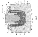
- FIG. 2 illustrates another preferred embodiment of the present invention showing a drill bit 40 positioned within a refractory vessel 42 and surrounded by granular, non-wettable particulate matter 44.
- the bit 40 is comprised of a layered-manufactured crown 46 of particulate material, a pre-machined steel blank 48 positioned within the crown 46, and machinable powder 50 such as tungsten in a ring-like shape surrounding a portion of the blank 48 and that can be later machined to provide an interface between the crown 46 and the blank 48.
- the crown 46 may be layered-manufactured from a laser-reactive, bonding agent coated, metallic powder or metallic powder, such as steel; tungsten carbide or a combination thereof, intermixed with a laser-reactive bonding agent such as a polymer, the polymer being heated with laser energy to bond the particles of metallic powder together. Once formed, the crown 46 is heated for infiltration during which time the crown 46 may shrink in size as the polymer dissipates or vaporizes or as the particles of metal powder sinter together.
- Dissipation and/or vaporization may be assisted by flowing a scavenging, reducing, or oxidizing gas, such as oxygen, hydrogen, or mixtures of oxygen and hydrogen with other gases, or by flowing a solvent such as certain alcohols, esters, hydrocarbons, petroleum, chlorinated solvents, ketones, and other organic or inorganic materials through the preformed crown 46 to dissolve and substantially remove the polymer from the crown 46.
- a scavenging, reducing, or oxidizing gas such as oxygen, hydrogen, or mixtures of oxygen and hydrogen with other gases
- a solvent such as certain alcohols, esters, hydrocarbons, petroleum, chlorinated solvents, ketones, and other organic or inorganic materials
- a "soft" or unconsolidated mold 41 formed from a granular, non-wettable, particulate matter 44 which may be comprised of casting sand, graphite, ceramic powder, silica, alumina, silicon carbide and/or combinations thereof, or other suitable materials known in the art that will not harden or otherwise become rigid during the infiltration process, may be able to maintain conformance to the shrinking crown 46 and thus maintain structural support of the crown 46 during infiltration. More specifically, as the polymer used to hold the particles of the layered-manufactured bit crown 46 together vaporizes, the particulate matter 44 may retain its unconsolidated quality to conform to any initial changes in size of the crown 46 and thus continue to provide support for the crown 46. In addition, the ability of the particulate matter 44 to be relatively compliant relative to the crown 46 may keep the infiltrant material 60 from pooling or accumulating in gaps that may otherwise form between a substantially rigid, dimensionally stable mold and a shrinking bit crown.
- a relatively loose material that solidifies or otherwise strengthens during the infiltration process by sintering, tacking, and/or chemically bonding may provide sufficient for the bit 40. That is, a particulate matter 44 could be selected that would retain its unconsolidated nature as the polymer, or other material initially binding the crown 46 together, is being removed and as the part is changing shape. At higher temperatures, however, after the polymer has been removed and the part is relatively dimensionally stable, the particulate matter 44 could solidify or otherwise strengthen to provide a more rigid support. Thus, in effect, the mold 41 conforms to the bit 40 during the beginning stages of furnacing and then becomes more firm during infiltration.
- a mold 41 that is initially substantially rigid, that weakens over time at the infiltration temperature, and is subsequently easily removed from the infiltrated component or assembly.
- sand bonded together with a polymer may provide rigid support until the polymer reaches a temperature near the infiltration temperature at which it melts, vaporizes and/or otherwise dissipates, leaving the sand in a relatively loose form.
- the particulate matter 44 is vibrated prior to infiltration to substantially pack the particulate matter 44 around the bit 40.
- the same or other non-wettable, particulate matter 52 can be provided in internal chambers or passageways 54, 56, and 58 of the bit 40.
- a vacuum may be applied to the mold assembly 43 to eliminate gas or vapor pockets and draw the infiltrant 60 past the blank 48 and through machinable powder 50 and crown 46.
- the mold assembly 43 may be pressurized to help force the infiltrant 60 through the bit 40.
- FIGS. 3 and 3A depict yet another preferred embodiment of the present invention illustrating another configuration for a mold 61 wherein an infiltrant has been incorporated into the layered-manufactured component 62.
- FIGS. 3 and 3A also illustrate the applicability of the present invention to non-drilling-related structures, such as an impeller 62 for use in a centrifugal pump.
- an impeller 62 for use in a centrifugal pump.
- a mold configuration similar to that illustrated in FIG. 2 may be utilized to expose a surface of the impeller 62 and allow the additional infiltrant to be placed adjacent the surface and imbibed therethrough.
- the particulate matter 64 of the mold 60 may be a wettable substance, such as steel and/or stainless steel to improve the thermoconductivity of the mold 60. Accordingly, it may be desirable to coat various surfaces of the component being infiltrated by spraying, painting, dipping or otherwise coating with a sealer or other non-wettable substance, such as boron nitride, aluminum nitride, Nicrobraze Green Stop-off manufactured by Wall Colmonoy, Inc. of Madison Heights, Michigan, and other materials such as Zircwash manufactured by Zyp Coatings, Inc. of Oak Ridge, Tennessee, so that the particulate matter 64 will not bond the particulate comprising the impeller 62 to the surrounding particulate matter 64.
- a sealer or other non-wettable substance such as boron nitride, aluminum nitride, Nicrobraze Green Stop-off manufactured by Wall Colmonoy, Inc. of Madison Heights, Michigan, and other materials such as Zircwash manufactured by Zyp Coatings,
- a resistive coating 66 may serve to keep the infiltrant within the confines of the impeller 62 so that the particulate matter 64 is not bonded to the impeller 62. Moreover, it is contemplated that such a resistive coating 66 may serve to improve the surface finish of the finished component whether it be a drill bit, such as bit 10, or some other component, such as impeller 62, by filling exterior and/or interior pores of the layered component and providing a more consistent surface to which the infiltrant can solidify. Thus, the resistive coating 66 may be incorporated into other embodiments herein described regardless of the material comprising the mold and/or support structure.
- the mold form may be broken off of the component and the material filling internal passages and other voids removed.
- the infiltrated component may simply be dumped out of the refractory vessel along with any particulate material contained therein.
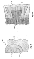
- FIG. 4 illustrates a partial view of a drill bit 70 positioned within a mold 72, the drill bit comprising a layered-manufactured body 74 and a preformed blade 76 adjacent the body 74.
- a blade 76 could provide external support for the body 74, with the mold 72 supporting the entire assembly.
- the method of infiltrating components and assemblies according to the present invention allows various components, such as interlocking, pre-infiltrated components 80 and 82 illustrated in partial view in FIG. 4A, to be preassembled and then infiltrated with mold 84 providing structural support.
- the invention has equal utility to any material where heat is utilized to transform a relatively weakly bonded component to a structurally stronger, self-supporting body.
Landscapes
- Engineering & Computer Science (AREA)
- Mechanical Engineering (AREA)
- Manufacturing & Machinery (AREA)
- Chemical & Material Sciences (AREA)
- Materials Engineering (AREA)
- Geology (AREA)
- Mining & Mineral Resources (AREA)
- Physics & Mathematics (AREA)
- Life Sciences & Earth Sciences (AREA)
- Environmental & Geological Engineering (AREA)
- Fluid Mechanics (AREA)
- General Life Sciences & Earth Sciences (AREA)
- Geochemistry & Mineralogy (AREA)
- Optics & Photonics (AREA)
- Composite Materials (AREA)
- Powder Metallurgy (AREA)
- Ceramic Products (AREA)
Applications Claiming Priority (3)
| Application Number | Priority Date | Filing Date | Title |
|---|---|---|---|
| US719281 | 1996-09-24 | ||
| US08/719,281 US5839329A (en) | 1994-03-16 | 1996-09-24 | Method for infiltrating preformed components and component assemblies |
| EP97942653A EP0958262B1 (de) | 1996-09-24 | 1997-09-23 | Verfahren zur infiltration von vorgeformten komponenten und zusammenstellungen von komponenten |
Related Parent Applications (2)
| Application Number | Title | Priority Date | Filing Date |
|---|---|---|---|
| EP97942653A Division-Into EP0958262B1 (de) | 1996-09-24 | 1997-09-23 | Verfahren zur infiltration von vorgeformten komponenten und zusammenstellungen von komponenten |
| EP97942653A Division EP0958262B1 (de) | 1996-09-24 | 1997-09-23 | Verfahren zur infiltration von vorgeformten komponenten und zusammenstellungen von komponenten |
Publications (1)
| Publication Number | Publication Date |
|---|---|
| EP1449604A1 true EP1449604A1 (de) | 2004-08-25 |
Family
ID=24889461
Family Applications (2)
| Application Number | Title | Priority Date | Filing Date |
|---|---|---|---|
| EP04004759A Withdrawn EP1449604A1 (de) | 1996-09-24 | 1997-09-23 | Verfahren zum Infiltrieren von vorgeformten Teilen |
| EP97942653A Expired - Lifetime EP0958262B1 (de) | 1996-09-24 | 1997-09-23 | Verfahren zur infiltration von vorgeformten komponenten und zusammenstellungen von komponenten |
Family Applications After (1)
| Application Number | Title | Priority Date | Filing Date |
|---|---|---|---|
| EP97942653A Expired - Lifetime EP0958262B1 (de) | 1996-09-24 | 1997-09-23 | Verfahren zur infiltration von vorgeformten komponenten und zusammenstellungen von komponenten |
Country Status (4)
| Country | Link |
|---|---|
| US (3) | US5839329A (de) |
| EP (2) | EP1449604A1 (de) |
| AU (1) | AU4430597A (de) |
| WO (1) | WO1998013317A2 (de) |
Cited By (2)
| Publication number | Priority date | Publication date | Assignee | Title |
|---|---|---|---|---|
| CN102430711A (zh) * | 2011-12-31 | 2012-05-02 | 中国兵器工业集团第七0研究所 | 一种增压器涡轮叶轮的快速制造方法 |
| CN103042179A (zh) * | 2012-12-20 | 2013-04-17 | 中国兵器工业集团第七〇研究所 | 一种压气机蜗壳的制造方法 |
Families Citing this family (75)
| Publication number | Priority date | Publication date | Assignee | Title |
|---|---|---|---|---|
| US6220117B1 (en) * | 1998-08-18 | 2001-04-24 | Baker Hughes Incorporated | Methods of high temperature infiltration of drill bits and infiltrating binder |
| US6454030B1 (en) * | 1999-01-25 | 2002-09-24 | Baker Hughes Incorporated | Drill bits and other articles of manufacture including a layer-manufactured shell integrally secured to a cast structure and methods of fabricating same |
| GB2384263B (en) * | 1999-01-25 | 2003-10-22 | Baker Hughes Inc | A mold for fabricating an earth-boring drill bit |
| US6247519B1 (en) | 1999-07-19 | 2001-06-19 | Her Majesty The Queen In Right Of Canada, As Represented By The Minister Of Natural Resources | Preform for magnesium metal matrix composites |
| US6460631B2 (en) | 1999-08-26 | 2002-10-08 | Baker Hughes Incorporated | Drill bits with reduced exposure of cutters |
| US6193915B1 (en) | 1999-09-03 | 2001-02-27 | Her Majesty The Queen In Right Of Canada, As Represented By The Minister Of Natural Resources | Process for fabricating low volume fraction metal matrix preforms |
| US6655234B2 (en) | 2000-01-31 | 2003-12-02 | Baker Hughes Incorporated | Method of manufacturing PDC cutter with chambers or passages |
| US6609043B1 (en) | 2000-04-25 | 2003-08-19 | Northrop Grumman Corporation | Method and system for constructing a structural foam part |
| US20030094730A1 (en) * | 2001-11-16 | 2003-05-22 | Varel International, Inc. | Method and fabricating tools for earth boring |
| US7461684B2 (en) * | 2002-08-20 | 2008-12-09 | The Ex One Company, Llc | Casting process and articles for performing same |
| US20040081573A1 (en) * | 2002-10-23 | 2004-04-29 | 3D Systems, Inc. | Binder removal in selective laser sintering |
| US6814926B2 (en) * | 2003-03-19 | 2004-11-09 | 3D Systems Inc. | Metal powder composition for laser sintering |
| DE10317473B3 (de) * | 2003-04-16 | 2005-02-03 | Daimlerchrysler Ag | Keramische Gussformen für den Metallguss und deren Herstellungsverfahren |
| US20040245024A1 (en) * | 2003-06-05 | 2004-12-09 | Kembaiyan Kumar T. | Bit body formed of multiple matrix materials and method for making the same |
| US7625521B2 (en) * | 2003-06-05 | 2009-12-01 | Smith International, Inc. | Bonding of cutters in drill bits |
| WO2005037726A2 (en) * | 2003-10-14 | 2005-04-28 | M Cubed Technologies, Inc. | Method for making cavities in metal-ceramic compoiste bodies, and articles made thereby |
| KR100738219B1 (ko) * | 2003-12-23 | 2007-07-12 | 삼성에스디아이 주식회사 | 유기 전계 발광 소자용 중간층 형성 물질 및 이를 이용한유기 전계 발광 소자 |
| US20050167871A1 (en) * | 2004-01-29 | 2005-08-04 | Sunil Kesavan | Gas-permeable molds for composite material fabrication and molding method |
| KR100466868B1 (ko) * | 2004-05-31 | 2005-01-24 | 허홍순 | 분배부재, 이를 갖는 수직축 임팩트 크러셔 및 분배부재의제조 방법 |
| GB2419202B (en) * | 2004-10-12 | 2006-10-25 | Smith International | A method of manufacturing a drill bit and a drill bit |
| CA2511309C (en) * | 2005-06-29 | 2010-02-16 | Ibex Welding Technologies Inc. | Method of hard coating a surface with carbide |
| US8141665B2 (en) | 2005-12-14 | 2012-03-27 | Baker Hughes Incorporated | Drill bits with bearing elements for reducing exposure of cutters |
| US7493965B1 (en) | 2006-04-12 | 2009-02-24 | Us Synthetic Corporation | Apparatuses and methods relating to cooling a subterranean drill bit and/or at least one cutting element during use |
| US8272295B2 (en) * | 2006-12-07 | 2012-09-25 | Baker Hughes Incorporated | Displacement members and intermediate structures for use in forming at least a portion of bit bodies of earth-boring rotary drill bits |
| US8349466B2 (en) * | 2007-02-22 | 2013-01-08 | Kennametal Inc. | Composite materials comprising a hard ceramic phase and a Cu-Ni-Sn alloy |
| US8858871B2 (en) * | 2007-03-27 | 2014-10-14 | Varel International Ind., L.P. | Process for the production of a thermally stable polycrystalline diamond compact |
| FR2914206B1 (fr) * | 2007-03-27 | 2009-09-04 | Sas Varel Europ Soc Par Action | Procede pour fabriquer une piece comprenant au moins un bloc en materiau dense constitue de particules dures dispersees dans une phase liante : application a des outils de coupe ou de forage. |
| US7857078B2 (en) * | 2007-05-29 | 2010-12-28 | Baker Hughes Incorporated | Cutting tools and methods of making the same |
| US7814997B2 (en) | 2007-06-14 | 2010-10-19 | Baker Hughes Incorporated | Interchangeable bearing blocks for drill bits, and drill bits including same |
| GB0716268D0 (en) * | 2007-08-21 | 2007-09-26 | Reedhycalog Uk Ltd | PDC cutter with stress diffusing structures |
| US20090311124A1 (en) * | 2008-06-13 | 2009-12-17 | Baker Hughes Incorporated | Methods for sintering bodies of earth-boring tools and structures formed during the same |
| FR2936817B1 (fr) * | 2008-10-07 | 2013-07-19 | Varel Europ | Procece pour fabriquer une piece comprenant un bloc en materiau dense du type carbure cemente, presentant un grandient de proprietes et piece obtenue |
| GB0818493D0 (en) * | 2008-10-09 | 2008-11-19 | Reedhycalog Uk Ltd | Drilling tool |
| US20100101750A1 (en) * | 2008-10-24 | 2010-04-29 | Tomczak Michael M | Two piece mold used in manufacture of PDC drill bits and method of using same |
| US8220566B2 (en) * | 2008-10-30 | 2012-07-17 | Baker Hughes Incorporated | Carburized monotungsten and ditungsten carbide eutectic particles, materials and earth-boring tools including such particles, and methods of forming such particles, materials, and tools |
| GB2467570B (en) * | 2009-02-09 | 2012-09-19 | Reedhycalog Uk Ltd | Cutting element |
| EP2425089A4 (de) * | 2009-04-30 | 2014-06-04 | Baker Hughes Inc | Lagerblöcke für bohrkronen, bohrkronenanordnungen mit lagerblöcken und zugehörige verfahren |
| US8945720B2 (en) * | 2009-08-06 | 2015-02-03 | National Oilwell Varco, L.P. | Hard composite with deformable constituent and method of applying to earth-engaging tool |
| US9309723B2 (en) * | 2009-10-05 | 2016-04-12 | Baker Hughes Incorporated | Drill bits and tools for subterranean drilling, methods of manufacturing such drill bits and tools and methods of directional and off center drilling |
| US8061408B2 (en) * | 2009-10-13 | 2011-11-22 | Varel Europe S.A.S. | Casting method for matrix drill bits and reamers |
| US8950518B2 (en) | 2009-11-18 | 2015-02-10 | Smith International, Inc. | Matrix tool bodies with erosion resistant and/or wear resistant matrix materials |
| US8814968B2 (en) * | 2010-01-14 | 2014-08-26 | National Oilwell Varco, L.P. | Thermally conductive sand mould shell for manufacturing a matrix bit |
| RU2561946C2 (ru) * | 2010-01-25 | 2015-09-10 | Варель Ероп С.А.С. | Самопозиционирование стальной заготовки в графитовой форме |
| US20110189504A1 (en) * | 2010-02-01 | 2011-08-04 | Los Alamos National Security, Llc | Preparation of metal carbide films |
| WO2011139519A2 (en) | 2010-04-28 | 2011-11-10 | Baker Hughes Incorporated | Earth-boring tools and methods of forming earth-boring tools |
| US8919463B2 (en) | 2010-10-25 | 2014-12-30 | National Oilwell DHT, L.P. | Polycrystalline diamond cutting element |
| GB2488508B (en) * | 2010-11-29 | 2015-10-07 | Halliburton Energy Services Inc | 3D-printed bodies for molding downhole equipment |
| GB2490087B (en) | 2010-11-29 | 2016-04-27 | Halliburton Energy Services Inc | Forming objects by infiltrating a printed matrix |
| GB2485848B (en) | 2010-11-29 | 2018-07-11 | Halliburton Energy Services Inc | Improvements in heat flow control for molding downhole equipment |
| US8997900B2 (en) | 2010-12-15 | 2015-04-07 | National Oilwell DHT, L.P. | In-situ boron doped PDC element |
| CN103476583B (zh) * | 2011-04-06 | 2016-11-02 | 埃斯科公司 | 使用硬焊的表面硬化耐磨部件及其制造的相关方法和总成 |
| US9027674B2 (en) | 2011-06-22 | 2015-05-12 | Halliburton Energy Services, Inc. | Custom shaped blank |
| GB2515667A (en) | 2012-05-30 | 2014-12-31 | Halliburton Energy Serv Inc | Manufacture of well tools with matrix materials |
| CN105142828B (zh) * | 2013-03-15 | 2017-10-24 | 山特维克知识产权股份有限公司 | 接合不同尺寸和形状的烧结部件的方法 |
| DE102014207510B4 (de) | 2014-04-17 | 2021-12-16 | Kennametal Inc. | Zerspanungswerkzeug sowie Verfahren zum Herstellen eines Zerspanungswerkzeugs |
| DE102014207507B4 (de) | 2014-04-17 | 2021-12-16 | Kennametal Inc. | Zerspanungswerkzeug sowie Verfahren zum Herstellen eines Zerspanungswerkzeugs |
| US9643282B2 (en) | 2014-10-17 | 2017-05-09 | Kennametal Inc. | Micro end mill and method of manufacturing same |
| EP3218160A4 (de) * | 2014-11-14 | 2018-10-17 | Nielsen-Cole, Cole | Verfahren und systeme zur generativen fertigung zur formung von verbundstoffmaterialien |
| US10472896B2 (en) * | 2014-11-19 | 2019-11-12 | Esco Group Llc | Downhole tool and method of manufacturing a tool |
| US9718126B2 (en) * | 2014-12-02 | 2017-08-01 | Halliburton Energy Services, Inc. | Mold assembly caps used in fabricating infiltrated downhole tools |
| WO2016209215A1 (en) * | 2015-06-23 | 2016-12-29 | Halliburton Energy Services, Inc. | Pre-diffused mandrel coating to provide enhanced bonding between metallic and composite components |
| PL3313617T3 (pl) | 2015-06-25 | 2023-08-14 | 3M Innovative Properties Company | Sposoby wytwarzania wyrobów ściernych z metalicznym środkiem wiążącym oraz wyroby ścierne z metalicznym środkiem wiążącym |
| US10704333B2 (en) | 2015-09-22 | 2020-07-07 | Halliburton Energy Services, Inc. | Metal matrix composite drill bits with reinforcing metal blanks |
| US20190234151A1 (en) * | 2016-08-02 | 2019-08-01 | Halliburton Energy Services, Inc. | Tools having a structural metal-matrix composite portion |
| WO2018057670A1 (en) | 2016-09-21 | 2018-03-29 | Singov Sergey | 3d printer |
| WO2018118566A1 (en) | 2016-12-23 | 2018-06-28 | 3M Innovative Properties Company | Polymer bond abrasive articles and methods of making them |
| CN110337347B (zh) | 2017-02-28 | 2022-07-12 | 3M创新有限公司 | 金属粘结磨料制品及制备金属粘结磨料制品的方法 |
| CN108798530A (zh) * | 2017-05-03 | 2018-11-13 | 史密斯国际有限公司 | 钻头主体构造 |
| CN108746633A (zh) * | 2018-05-10 | 2018-11-06 | 苏州国立塑料制品有限公司 | 一种金属模具的制备工艺 |
| WO2021217044A1 (en) | 2020-04-23 | 2021-10-28 | Saint-Gobain Abrasives, Inc. | System and method for conducting an abrasive operation |
| JP2024509813A (ja) | 2021-03-05 | 2024-03-05 | サンーゴバン アブレイシブズ,インコーポレイティド | 研磨物品及びそれを形成するための方法 |
| WO2022187720A1 (en) | 2021-03-05 | 2022-09-09 | Saint-Gobain Abrasives, Inc. | Abrasive articles and methods for forming same |
| CN118541240B (zh) | 2021-12-30 | 2025-11-07 | 圣戈班磨料磨具有限公司 | 磨料制品及其形成方法 |
| US12064850B2 (en) | 2021-12-30 | 2024-08-20 | Saint-Gobain Abrasives, Inc. | Abrasive articles and methods for forming same |
| CN116984611B (zh) * | 2023-09-18 | 2023-12-19 | 新乡市胜达过滤净化技术有限公司 | 一种金属粉末烧结滤芯成型工艺及成型装置 |
Citations (5)
| Publication number | Priority date | Publication date | Assignee | Title |
|---|---|---|---|---|
| GB809133A (en) * | 1955-04-19 | 1959-02-18 | Sintercast Corp America | Improvements in and relating to the production of hollow thermal elements |
| EP0323945A2 (de) * | 1988-01-07 | 1989-07-12 | Lanxide Technology Company, Lp. | Verfahren zur Herstellung eines Verbundwerkstoffes mit Metall-Matrix mit Hilfe einer Sperre |
| US5337800A (en) * | 1992-09-09 | 1994-08-16 | Cook Arnold J | Reactive coating |
| US5433280A (en) * | 1994-03-16 | 1995-07-18 | Baker Hughes Incorporated | Fabrication method for rotary bits and bit components and bits and components produced thereby |
| US5487420A (en) * | 1990-05-09 | 1996-01-30 | Lanxide Technology Company, Lp | Method for forming metal matrix composite bodies by using a modified spontaneous infiltration process and products produced thereby |
Family Cites Families (44)
| Publication number | Priority date | Publication date | Assignee | Title |
|---|---|---|---|---|
| DE672257C (de) * | 1936-11-11 | 1939-02-27 | Meutsch Voigtlaender & Co Vorm | Verfahren zum Herstellen von Werkstuecken, die mit Hartmetallauflagen oder -einlagen versehen sind |
| US2612443A (en) * | 1947-12-26 | 1952-09-30 | Sintereast Corp Of America | Powder metallurgy |
| US2843501A (en) * | 1956-08-01 | 1958-07-15 | Sintercast Corp America | Method for the precision production of infiltrated articles |
| US3471921A (en) * | 1965-12-23 | 1969-10-14 | Shell Oil Co | Method of connecting a steel blank to a tungsten bit body |
| US3823002A (en) * | 1972-05-05 | 1974-07-09 | Minnesota Mining & Mfg | Precision molded refractory articles |
| US3757879A (en) * | 1972-08-24 | 1973-09-11 | Christensen Diamond Prod Co | Drill bits and methods of producing drill bits |
| US3757878A (en) * | 1972-08-24 | 1973-09-11 | Christensen Diamond Prod Co | Drill bits and method of producing drill bits |
| GB1572543A (en) * | 1978-05-26 | 1980-07-30 | Smit & Sons Diamond Tools | Drilling tools |
| US4484644A (en) * | 1980-09-02 | 1984-11-27 | Ingersoll-Rand Company | Sintered and forged article, and method of forming same |
| US4398952A (en) * | 1980-09-10 | 1983-08-16 | Reed Rock Bit Company | Methods of manufacturing gradient composite metallic structures |
| ZW12583A1 (en) * | 1982-06-08 | 1983-08-24 | Boart Int Ltd | Drilling bit |
| DE3479143D1 (en) * | 1983-12-03 | 1989-08-31 | Reed Tool Co | Improvements in or relating to the manufacture of rotary drill bits |
| DE3347501C3 (de) * | 1983-12-29 | 1993-12-02 | Uwe Christian Seefluth | Bohrwerkzeug mit Hartmetalleinsatzkörper, Herstellverfahren für Hartmetalleinsatzkörper |
| US4863538A (en) * | 1986-10-17 | 1989-09-05 | Board Of Regents, The University Of Texas System | Method and apparatus for producing parts by selective sintering |
| BR8707510A (pt) * | 1986-10-17 | 1989-02-21 | Univ Texas | Metodo e aparelhagem para produzir pecas por sinterizacao seletiva |
| US5017753A (en) * | 1986-10-17 | 1991-05-21 | Board Of Regents, The University Of Texas System | Method and apparatus for producing parts by selective sintering |
| US5155324A (en) * | 1986-10-17 | 1992-10-13 | Deckard Carl R | Method for selective laser sintering with layerwise cross-scanning |
| US4840763A (en) * | 1987-08-06 | 1989-06-20 | Ltv Aerospace And Defense Company | Method for the production of reinforced composites |
| US5090491A (en) * | 1987-10-13 | 1992-02-25 | Eastman Christensen Company | Earth boring drill bit with matrix displacing material |
| US4884477A (en) * | 1988-03-31 | 1989-12-05 | Eastman Christensen Company | Rotary drill bit with abrasion and erosion resistant facing |
| US4919013A (en) * | 1988-09-14 | 1990-04-24 | Eastman Christensen Company | Preformed elements for a rotary drill bit |
| AU4504089A (en) * | 1988-10-05 | 1990-05-01 | Michael Feygin | An improved apparatus and method for forming an integral object from laminations |
| US5284695A (en) * | 1989-09-05 | 1994-02-08 | Board Of Regents, The University Of Texas System | Method of producing high-temperature parts by way of low-temperature sintering |
| US5182170A (en) * | 1989-09-05 | 1993-01-26 | Board Of Regents, The University Of Texas System | Method of producing parts by selective beam interaction of powder with gas phase reactant |
| US5156697A (en) * | 1989-09-05 | 1992-10-20 | Board Of Regents, The University Of Texas System | Selective laser sintering of parts by compound formation of precursor powders |
| GB8921017D0 (en) * | 1989-09-16 | 1989-11-01 | Astec Dev Ltd | Drill bit or corehead manufacturing process |
| US5000273A (en) * | 1990-01-05 | 1991-03-19 | Norton Company | Low melting point copper-manganese-zinc alloy for infiltration binder in matrix body rock drill bits |
| US5155321A (en) * | 1990-11-09 | 1992-10-13 | Dtm Corporation | Radiant heating apparatus for providing uniform surface temperature useful in selective laser sintering |
| AU9065991A (en) * | 1990-11-09 | 1992-06-11 | Dtm Corporation | Controlled gas flow for selective laser sintering |
| US5385780A (en) * | 1990-12-05 | 1995-01-31 | The B. F. Goodrich Company | Sinterable mass of polymer powder having resistance to caking and method of preparing the mass |
| SE500049C2 (sv) * | 1991-02-05 | 1994-03-28 | Sandvik Ab | Hårdmetallkropp med ökad seghet för mineralavverkning samt sätt att framställa denna |
| EP0536762B1 (de) * | 1991-10-09 | 1997-09-03 | Smith International, Inc. | Diamant-Schneideinsatz mit einer konvexen Schneidfläche |
| US5252264A (en) * | 1991-11-08 | 1993-10-12 | Dtm Corporation | Apparatus and method for producing parts with multi-directional powder delivery |
| EP0599371B1 (de) * | 1992-11-18 | 1997-09-17 | Philips Composants Et Semiconducteurs | Verfahren und Sinterungsmitteln für Ferritsektoren |
| US5342919A (en) * | 1992-11-23 | 1994-08-30 | Dtm Corporation | Sinterable semi-crystalline powder and near-fully dense article formed therewith |
| US5304329A (en) * | 1992-11-23 | 1994-04-19 | The B. F. Goodrich Company | Method of recovering recyclable unsintered powder from the part bed of a selective laser-sintering machine |
| US5352405A (en) * | 1992-12-18 | 1994-10-04 | Dtm Corporation | Thermal control of selective laser sintering via control of the laser scan |
| US5373907A (en) * | 1993-01-26 | 1994-12-20 | Dresser Industries, Inc. | Method and apparatus for manufacturing and inspecting the quality of a matrix body drill bit |
| DE4322084A1 (de) * | 1993-07-02 | 1995-01-12 | Abb Research Ltd | Verfahren zur Herstellung eines Setters |
| US5441121A (en) * | 1993-12-22 | 1995-08-15 | Baker Hughes, Inc. | Earth boring drill bit with shell supporting an external drilling surface |
| GB2290604A (en) * | 1994-06-14 | 1996-01-03 | Ea Tech Ltd | Apparatus and method for firing ceramic sheets |
| GB9500286D0 (en) * | 1995-01-07 | 1995-03-01 | Camco Drilling Group Ltd | Improvements in or relating to the manufacture of rotary drill bits |
| US5728345A (en) * | 1995-03-03 | 1998-03-17 | General Motors Corporation | Method for making an electrode for electrical discharge machining by use of a stereolithography model |
| US5737980A (en) * | 1996-06-04 | 1998-04-14 | Smith International, Inc. | Brazing receptacle for improved PCD cutter retention |
-
1996
- 1996-09-24 US US08/719,281 patent/US5839329A/en not_active Expired - Lifetime
-
1997
- 1997-09-23 EP EP04004759A patent/EP1449604A1/de not_active Withdrawn
- 1997-09-23 AU AU44305/97A patent/AU4430597A/en not_active Abandoned
- 1997-09-23 EP EP97942653A patent/EP0958262B1/de not_active Expired - Lifetime
- 1997-09-23 WO PCT/US1997/016859 patent/WO1998013317A2/en not_active Ceased
-
1998
- 1998-11-17 US US09/192,856 patent/US6354362B1/en not_active Expired - Fee Related
-
2002
- 2002-03-11 US US10/095,548 patent/US6581671B2/en not_active Expired - Fee Related
Patent Citations (5)
| Publication number | Priority date | Publication date | Assignee | Title |
|---|---|---|---|---|
| GB809133A (en) * | 1955-04-19 | 1959-02-18 | Sintercast Corp America | Improvements in and relating to the production of hollow thermal elements |
| EP0323945A2 (de) * | 1988-01-07 | 1989-07-12 | Lanxide Technology Company, Lp. | Verfahren zur Herstellung eines Verbundwerkstoffes mit Metall-Matrix mit Hilfe einer Sperre |
| US5487420A (en) * | 1990-05-09 | 1996-01-30 | Lanxide Technology Company, Lp | Method for forming metal matrix composite bodies by using a modified spontaneous infiltration process and products produced thereby |
| US5337800A (en) * | 1992-09-09 | 1994-08-16 | Cook Arnold J | Reactive coating |
| US5433280A (en) * | 1994-03-16 | 1995-07-18 | Baker Hughes Incorporated | Fabrication method for rotary bits and bit components and bits and components produced thereby |
Cited By (2)
| Publication number | Priority date | Publication date | Assignee | Title |
|---|---|---|---|---|
| CN102430711A (zh) * | 2011-12-31 | 2012-05-02 | 中国兵器工业集团第七0研究所 | 一种增压器涡轮叶轮的快速制造方法 |
| CN103042179A (zh) * | 2012-12-20 | 2013-04-17 | 中国兵器工业集团第七〇研究所 | 一种压气机蜗壳的制造方法 |
Also Published As
| Publication number | Publication date |
|---|---|
| EP0958262B1 (de) | 2004-12-29 |
| AU4430597A (en) | 1998-04-17 |
| US5839329A (en) | 1998-11-24 |
| EP0958262A2 (de) | 1999-11-24 |
| WO1998013317A3 (en) | 1998-09-17 |
| US6354362B1 (en) | 2002-03-12 |
| WO1998013317A2 (en) | 1998-04-02 |
| US6581671B2 (en) | 2003-06-24 |
| US20020096306A1 (en) | 2002-07-25 |
Similar Documents
| Publication | Publication Date | Title |
|---|---|---|
| US5839329A (en) | Method for infiltrating preformed components and component assemblies | |
| US6454030B1 (en) | Drill bits and other articles of manufacture including a layer-manufactured shell integrally secured to a cast structure and methods of fabricating same | |
| US7461684B2 (en) | Casting process and articles for performing same | |
| US6209420B1 (en) | Method of manufacturing bits, bit components and other articles of manufacture | |
| US11904391B2 (en) | Additive manufacturing of articles comprising beryllium | |
| US6073518A (en) | Bit manufacturing method | |
| EP1860084B1 (de) | Verfahren zur Herstellung von Schaumkomponenten aus metallischen Zusammensetzungen | |
| AU681235B2 (en) | Fabrication method for matrix type drag bits and bits produced thereby | |
| EP2437903A2 (de) | Verfahrensysteme und zusammensetzungen zur herstellung von bohrlochwerkzeugen und bohrlochwerkzeugteile | |
| GB2307699A (en) | Rotary drag bit | |
| GB2384262A (en) | A method of fabricating an earth-boring drill bit | |
| WO2026062406A1 (en) | Process for producing a syntactic composite foam in a metal matrix having an ordered arrangement |
Legal Events
| Date | Code | Title | Description |
|---|---|---|---|
| PUAI | Public reference made under article 153(3) epc to a published international application that has entered the european phase |
Free format text: ORIGINAL CODE: 0009012 |
|
| AC | Divisional application: reference to earlier application |
Ref document number: 0958262 Country of ref document: EP Kind code of ref document: P |
|
| AK | Designated contracting states |
Kind code of ref document: A1 Designated state(s): DE GB IT |
|
| 17P | Request for examination filed |
Effective date: 20050211 |
|
| AKX | Designation fees paid |
Designated state(s): GB IT |
|
| REG | Reference to a national code |
Ref country code: DE Ref legal event code: 8566 |
|
| STAA | Information on the status of an ep patent application or granted ep patent |
Free format text: STATUS: THE APPLICATION IS DEEMED TO BE WITHDRAWN |
|
| 18D | Application deemed to be withdrawn |
Effective date: 20051130 |