EP1449656A1 - Groupe d'impression pour impression indirecte - Google Patents
Groupe d'impression pour impression indirecte Download PDFInfo
- Publication number
- EP1449656A1 EP1449656A1 EP03405096A EP03405096A EP1449656A1 EP 1449656 A1 EP1449656 A1 EP 1449656A1 EP 03405096 A EP03405096 A EP 03405096A EP 03405096 A EP03405096 A EP 03405096A EP 1449656 A1 EP1449656 A1 EP 1449656A1
- Authority
- EP
- European Patent Office
- Prior art keywords
- cylinder
- printing unit
- unit according
- printing
- shells
- Prior art date
- Legal status (The legal status is an assumption and is not a legal conclusion. Google has not performed a legal analysis and makes no representation as to the accuracy of the status listed.)
- Withdrawn
Links
- 238000007639 printing Methods 0.000 title claims abstract description 50
- 229910052782 aluminium Inorganic materials 0.000 claims abstract description 5
- XAGFODPZIPBFFR-UHFFFAOYSA-N aluminium Chemical compound [Al] XAGFODPZIPBFFR-UHFFFAOYSA-N 0.000 claims abstract description 5
- 239000000463 material Substances 0.000 claims abstract description 5
- 210000003746 feather Anatomy 0.000 claims description 2
- 238000007645 offset printing Methods 0.000 description 2
- 230000002093 peripheral effect Effects 0.000 description 2
- 238000006243 chemical reaction Methods 0.000 description 1
- 230000000052 comparative effect Effects 0.000 description 1
- 239000007769 metal material Substances 0.000 description 1
- 238000000034 method Methods 0.000 description 1
- 238000000926 separation method Methods 0.000 description 1
- 239000002904 solvent Substances 0.000 description 1
Images

Classifications
-
- B—PERFORMING OPERATIONS; TRANSPORTING
- B41—PRINTING; LINING MACHINES; TYPEWRITERS; STAMPS
- B41F—PRINTING MACHINES OR PRESSES
- B41F13/00—Common details of rotary presses or machines
- B41F13/08—Cylinders
-
- B—PERFORMING OPERATIONS; TRANSPORTING
- B41—PRINTING; LINING MACHINES; TYPEWRITERS; STAMPS
- B41F—PRINTING MACHINES OR PRESSES
- B41F13/00—Common details of rotary presses or machines
- B41F13/44—Arrangements to accommodate interchangeable cylinders of different sizes to enable machine to print on areas of different sizes
Definitions
- the invention relates to a printing unit for indirect printing, with at least one plate cylinder, a blanket cylinder and an impression cylinder, at least to change the printing length the plate cylinder and the blanket cylinder each a cylinder core and on this a replaceable part exhibit.
- Printing units of the type mentioned are known. These have one Insert with a plate cylinder, a blanket cylinder and Impression cylinder on.
- the drive is usually from the impression cylinder on the blanket cylinder and from this on the plate cylinder and finally into the inking unit.
- the drive can also from the inking unit via the plate and blanket cylinder on the impression cylinder.
- a printing unit has become known from DE 199 55 084 A, at which is applied to cylinder cores with variable size sleeves are.
- the cylinder cores are the same and have one Diameter which is smaller than the corresponding minimum printing length.
- the cylinder cores are fixed on one side.
- To the A bearing plate must be replaced on one side to replace the pressure sleeves opened so that the sleeves can be pushed through.
- the cylinder cores are only on the drive side stored, which requires complex storage.
- Such pressure sleeves also called “sleeves” are comparative soft elements that give way under high pressure so that Concentricity errors result and especially on raw paper no more precise Pressure results.
- a printing unit has also become known in the prior art, in which the cylinder cores are designed as air axes. For the format change or to replace the sleeve must also a side wall can be opened here.
- DE 195 34 651 also discloses a printing unit for indirect Pressure provided on the cylinder with interchangeable sleeves are. It is also provided here that all cylinders each separately powered and all cylinders for one Center distance change to the adjacent cylinder are formed.
- EP 1 101 611 A discloses a printing unit for offset printing, with the at least two pressure cylinders on pivotable arms or are stored in a slot of a bearing plate.
- the impression cylinders can also change the format through an opening a bearing plate can be removed.
- the storage is also here comparatively complex.
- DE 35 43 704 A discloses a method for printing on Print media with at least one printing form.
- the printing form shows the shape of a sleeve that is interchangeable on a rotating body is attached. This means that prints can be varied in format within wide limits getting produced.
- the invention has for its object a printing unit of the above Way to create where the print length is easier and can be changed inexpensively.
- the task is solved in a generic printing unit in that that the interchangeable parts mentioned in each case from partial shells exist that releasably attached to the respective cylinder core are.
- the parts mentioned are in the inventive Printing unit therefore not sleeves, but partial shells that are attached to the respective Cylinder core are releasably attached.
- the Part shells to be replaced can easily be changed by the respective Cylinder core removed and replaced with new partial shells become.
- a major advantage of the inventive Druckmaschinees also consists in that when changing the format Paper web does not have to be torn off and drawn in again.
- the Operator side and drive side can be designed as usual and expensive bearings for the printing cylinders are not required.
- the partial shells are preferably designed as half shells.
- the interchangeable part can also consist of three or more partial shells consist. According to a further training, these partial shells are the invention connected to each other with connecting means and clamped on the core.
- the partial shells are according to a further development of the invention provided with a transverse slot to which a pressure plate can be attached is.
- the blanket cylinder has a rubber blanket that is glued to the partial shells is.
- the partial shells have of the blanket cylinder on a clamping spindle with which the rubber blanket is stretched onto the partial shells. This makes possible a particularly easy change of the rubber blanket.
- the partial shells exist made of aluminum or another material of comparable density.
- the partial shells are comparatively small Weight and can therefore be easily changed by hand.
- Aluminum or another suitable metal material has the advantage that the partial shells are resistant to solvents and are not damaged when changing the rubber blankets becomes. Because such materials are also comparatively hard there are no runout errors even at high pressure.
- FIG. 1 shows a printing unit 1 for offset printing or indirect printing Print.
- the printing unit 1 has a frame 20 which 4, a first bearing plate 2 on the drive side and on the operator side has a second bearing plate 3.
- On these bearing plates 2 and 3 are a plate cylinder 4, a blanket cylinder 5 and an impression cylinder 6 stored.
- the plate cylinder 4 is inked with an inking unit 21, as is known.
- the drive preferably takes place from the impression cylinder 6 on the blanket cylinder 5 and from this to the plate cylinder 4 and from this into the inking unit 21.
- the cylinders 4, 5 and 6 mentioned are on the bearing plates 2 and 3, for example with known and Link guides, not shown here, mounted so that changes in center distance possible are. It is also an execution conceivable, in which only the blanket cylinder 5 is adjustable is stored.
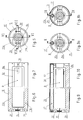
- the blanket cylinder 5 has a cylinder according to Figure 3.
- core 8 which according to FIG. 4 has a bearing 9 at its ends on the bearing plate 3 and with a bearing 10 on the bearing plate 2 is rotatably mounted.
- the circular cylindrical in cross section and cylinder core 8 provided with a feather key 8a has a peripheral surface 14 (Fig. 4) on which an interchangeable Part 11 is put on.
- This interchangeable part 11 is made from at least two half-shells 11a and 11b, which according to FIG with fasteners, for example clamping screws 15, releasable are interconnected. Connect the clamping screws 15 the two half-shells 11a and 11b such that these on the Cylinder core 8 are clamped.
- the key 8a engages in one Groove 31 of the half-shell 11b, so that the replaceable Part 11 is also positively connected to the cylinder core 8.
- the two half-shells turn 11a and 11b with. As FIG. 4 shows, this extends replaceable part 11 essentially over the entire length the circular cylindrical peripheral surface 14.
- the two half-shells 11a and 11b form an outer side 16, which is also circular in cross section according to FIG. 5 and to which a rubber blanket 13 is applied.
- the rubber blanket 13 is detachable in a known manner on the two half-shells 11a and 11b glued on.
- the blanket cylinder 26 according to FIGS. 8 to 10 has a partial shell 25a a clamping spindle 17 with which the rubber blanket 13 clamped onto a replaceable part 25 is, a longitudinal edge 13a of the blanket 13 in known Way is inserted into a groove 24.
- Such clamping spindles 17th are known per se.
- the half shells 11a and 11b can be loosened after loosening the clamping screws 15 removed from the cylinder core 8 and by others Half shells 11a 'and 11b' ( Figure 2) are replaced. These half shells According to FIG. 2, 11a 'and 11b' have a smaller one Scope.
- the larger scope according to FIG. 1 is, for example 24 "and the smaller circumference according to FIG. 2 17". But there are other sizes are also possible.
- the blanket 13 is of course also changed. With the half-shells 25a and 25b of the blanket cylinder 26 the blanket 13 is replaced by loosening or tensioning the clamping spindle 17.
- the two half-shells 11a and 11b and 25a and 25b exist preferably made of aluminum or a material that is similar has relatively low density.
- the weight of the half shells 11a and 11b and 25a and 25b can through recesses on the inside 32 can be reduced even further. So that the half-shells 11a and 11b as well as 25a and 25b particularly easily and safely by hand can be changed, they each face the front Grip recesses 22 and 23 on which they are gripped by hand can. Through these recessed grips 22 and 23 are also the clamping screws 15 used, the flanges 28 and 29 firmly together connect. The flanges 28 and 29 form a flat one Separation gap 33, as shown for example in FIG. 5.
- the shell 11b has a groove 31, which is interrupted by the recess 32 and for positive connection the key 8a of the cylinder 8 receives. With this groove 31 and the key 8a is simultaneously the interchangeable part 11 or 11 'positioned on the cylinder core 8 and thus the angular position of the interchangeable part 11 established.
- the key 8a can also by a radial, not shown here, positioning pin of the cylinder core 8 'to be replaced.
- the plate cylinder 4 is constructed essentially the same as the blanket cylinder 5 or 26 and has one according to Figure 1 circular cylindrical cylinder core 7, which essentially the same as the cylinder core 8 on the bearing plates 2 and 3 is.
- a replaceable part 12 is on the cylinder core 7 put on, which consists of two half-shells 12a and 12b, the also connected to each other with clamping screws 15 and with the cylinder core 7 is clamped and positive with key and groove are connected.
- the two half shells 12a and 12b form a circular cylindrical circumference 18, on which one here Pressure plate, not shown, is arranged. This pressure plate is in a known manner with a clamping spindle, not shown here attached.
- the two half shells 12a and 12b When changing the format, the two half shells 12a and 12b also replaced by half shells 12a 'and 12b'. This is done in the same way as with the blanket cylinder 5. Die Circumferences of the plate cylinder 4 and the blanket cylinder 5 are after the change of format mentioned above smaller as can be seen as previously. The scope of the impression cylinder 6 is one Format change is not changed and is therefore only postponed.
- the corresponding are for changing the center distance Bearings 9 and 10 in backdrop guides, not shown here, Swivel arms or eccentric bushes, which have the corresponding Allow repositioning.
- the impression cylinder 6 is preferably also adjustable the bearing plates 2 and 3 stored.
- the blanket 13 is placed on the blanket cylinder 4 ' glued or stretched on the blanket cylinder.
- the Printing plate is in a known manner on the plate cylinder 5 ' attached. If the diameter changes, the drive must also be adjusted become. Be the cylinder cores 7 and 8 with one here own motor, not shown, is driven accordingly adjusted the speed. If the drive takes place via not shown here Gears, they must also according to the format change. After adjusting the center distances, you can be printed in the new format.
Landscapes
- Engineering & Computer Science (AREA)
- Mechanical Engineering (AREA)
- Rotary Presses (AREA)
Priority Applications (1)
| Application Number | Priority Date | Filing Date | Title |
|---|---|---|---|
| EP03405096A EP1449656A1 (fr) | 2003-02-19 | 2003-02-19 | Groupe d'impression pour impression indirecte |
Applications Claiming Priority (1)
| Application Number | Priority Date | Filing Date | Title |
|---|---|---|---|
| EP03405096A EP1449656A1 (fr) | 2003-02-19 | 2003-02-19 | Groupe d'impression pour impression indirecte |
Publications (1)
| Publication Number | Publication Date |
|---|---|
| EP1449656A1 true EP1449656A1 (fr) | 2004-08-25 |
Family
ID=32731628
Family Applications (1)
| Application Number | Title | Priority Date | Filing Date |
|---|---|---|---|
| EP03405096A Withdrawn EP1449656A1 (fr) | 2003-02-19 | 2003-02-19 | Groupe d'impression pour impression indirecte |
Country Status (1)
| Country | Link |
|---|---|
| EP (1) | EP1449656A1 (fr) |
Cited By (4)
| Publication number | Priority date | Publication date | Assignee | Title |
|---|---|---|---|---|
| DE102006008348A1 (de) * | 2006-02-21 | 2007-08-30 | Windmöller & Hölscher Kg | Druckmaschine |
| DE102007017097A1 (de) * | 2006-09-15 | 2008-03-27 | Sdf Schnitt-Druck-Falz Spezialmaschinen Gmbh | Druckzylinder-Wechselsystem für drucklängenveränderbare Druckwerke in einer Vollrotations-Druckmaschine |
| DE102008021965A1 (de) * | 2008-05-02 | 2009-11-05 | Manroland Ag | Produktverlangsamungsstation und Gegenwalze dafür |
| DE102011055817A1 (de) | 2011-11-29 | 2013-05-29 | Sdf Schnitt-Druck-Falz Spezialmaschinen Gmbh | Druckwerk für den Nass-Offset-Druck |
Citations (9)
| Publication number | Priority date | Publication date | Assignee | Title |
|---|---|---|---|---|
| US1358843A (en) * | 1917-01-17 | 1920-11-16 | Grass William | Printing-press |
| US1868963A (en) * | 1930-02-07 | 1932-07-26 | Cottrell C B & Sons Co | Multicolor rotary printing press |
| US2659306A (en) * | 1951-03-08 | 1953-11-17 | Hamilton Tool Co | Means for varying the circumference of printing cylinders |
| GB827631A (en) * | 1957-07-25 | 1960-02-10 | Schnellpressenfab Heidelberg | Improvements in or relating to a curved cylinder for relief printing machines havinga removable stereotype plate carrying jacket |
| DE3543704A1 (de) | 1985-12-11 | 1987-06-19 | Md Papierfabrik Pasing Nicolau | Vorrichtung und verfahren zum bedrucken einer bahn |
| US4817527A (en) * | 1986-03-06 | 1989-04-04 | R.R. Donnelley & Sons Company | Printing blanket with carrier plate and method of assembly |
| DE19534651A1 (de) | 1995-09-19 | 1997-03-20 | Roland Man Druckmasch | Druckwerk für indirekten Druck |
| DE19955084A1 (de) | 1999-11-15 | 2001-05-23 | Giebeler Druckmaschinen Gmbh | Vollrotations-Nassoffset-Druckverfahren zur Herstellung veränderlicher Drucklängen |
| EP1101611A1 (fr) | 1999-11-19 | 2001-05-23 | Drent Holding B.V. | Dispositif pour supporter et positionner d'une manière échangeable des cylindres d'impression dans une machine d'impression offset |
-
2003
- 2003-02-19 EP EP03405096A patent/EP1449656A1/fr not_active Withdrawn
Patent Citations (9)
| Publication number | Priority date | Publication date | Assignee | Title |
|---|---|---|---|---|
| US1358843A (en) * | 1917-01-17 | 1920-11-16 | Grass William | Printing-press |
| US1868963A (en) * | 1930-02-07 | 1932-07-26 | Cottrell C B & Sons Co | Multicolor rotary printing press |
| US2659306A (en) * | 1951-03-08 | 1953-11-17 | Hamilton Tool Co | Means for varying the circumference of printing cylinders |
| GB827631A (en) * | 1957-07-25 | 1960-02-10 | Schnellpressenfab Heidelberg | Improvements in or relating to a curved cylinder for relief printing machines havinga removable stereotype plate carrying jacket |
| DE3543704A1 (de) | 1985-12-11 | 1987-06-19 | Md Papierfabrik Pasing Nicolau | Vorrichtung und verfahren zum bedrucken einer bahn |
| US4817527A (en) * | 1986-03-06 | 1989-04-04 | R.R. Donnelley & Sons Company | Printing blanket with carrier plate and method of assembly |
| DE19534651A1 (de) | 1995-09-19 | 1997-03-20 | Roland Man Druckmasch | Druckwerk für indirekten Druck |
| DE19955084A1 (de) | 1999-11-15 | 2001-05-23 | Giebeler Druckmaschinen Gmbh | Vollrotations-Nassoffset-Druckverfahren zur Herstellung veränderlicher Drucklängen |
| EP1101611A1 (fr) | 1999-11-19 | 2001-05-23 | Drent Holding B.V. | Dispositif pour supporter et positionner d'une manière échangeable des cylindres d'impression dans une machine d'impression offset |
Cited By (6)
| Publication number | Priority date | Publication date | Assignee | Title |
|---|---|---|---|---|
| DE102006008348A1 (de) * | 2006-02-21 | 2007-08-30 | Windmöller & Hölscher Kg | Druckmaschine |
| DE102006008348B4 (de) * | 2006-02-21 | 2008-08-07 | Windmöller & Hölscher Kg | Druckmaschine |
| DE102007017097A1 (de) * | 2006-09-15 | 2008-03-27 | Sdf Schnitt-Druck-Falz Spezialmaschinen Gmbh | Druckzylinder-Wechselsystem für drucklängenveränderbare Druckwerke in einer Vollrotations-Druckmaschine |
| DE102007017097B4 (de) * | 2006-09-15 | 2011-06-01 | Sdf Schnitt-Druck-Falz Spezialmaschinen Gmbh | Druckzylinder-Wechselvorrichtung für druckenlängenveränderbare Druckwerke in einer Vollrotations-Druckmaschine |
| DE102008021965A1 (de) * | 2008-05-02 | 2009-11-05 | Manroland Ag | Produktverlangsamungsstation und Gegenwalze dafür |
| DE102011055817A1 (de) | 2011-11-29 | 2013-05-29 | Sdf Schnitt-Druck-Falz Spezialmaschinen Gmbh | Druckwerk für den Nass-Offset-Druck |
Similar Documents
| Publication | Publication Date | Title |
|---|---|---|
| DE19740129C2 (de) | Rotationsdruckmaschine mit stirnseitig freilegbaren Zylindern | |
| DE69815115T2 (de) | Druckmaschine mit veränderlichem abstellmechanismus | |
| DE3203879A1 (de) | Offset-bogen-rotationsdruckmaschine | |
| EP0924067B1 (fr) | Cylindre d'impression pour une machine à imprimer des feuilles | |
| EP1568494B1 (fr) | Dispositif pour réaliser des impression à format variable dans des machines à imprimer offset | |
| DE2130278C3 (de) | Druckeinheit einer Rollenrotationsdruckmaschine zum wahlweisen Hoch- oder Flachdruck | |
| DE9116367U1 (de) | Zylinder für die Papierführung an Bogenrotationsdruckmaschinen | |
| DE102004051041B3 (de) | Druckplattenzylinder | |
| EP1449656A1 (fr) | Groupe d'impression pour impression indirecte | |
| DE10066162B4 (de) | Druckwerk einer Rotationsdruckmaschine | |
| EP1923214A2 (fr) | Unité d'impression d'une presse dotée de deux doubles groupes d'impressions agencés l'un sur l'autre | |
| EP1917142A1 (fr) | Systeme et procede pour changer une longueur d'impression | |
| DE102011100758A1 (de) | Verarbeitungsmaschine mit wenigstens einer Druckeinheit | |
| DE10046367B4 (de) | Antrieb einer Druckeinheit | |
| EP1572458B1 (fr) | Presse rotative a bobines | |
| DE3318316A1 (de) | Steuereinrichtung fuer die druckzylinder von druckmaschinen | |
| DE2949957C2 (de) | Druckeinheit für eine Rollen-Rotations-Offsetdruckmaschine | |
| DE471734C (de) | Formzylinder fuer Rotationsdruckmaschinen, insbesondere Rotationsgummidruckmaschinen | |
| DE10122227B4 (de) | Speichertrommel in Wendeeinrichtungen von Bogendruckmaschinen | |
| DE102009001083A1 (de) | Druck- oder Farbwerk | |
| DE20118941U1 (de) | Farbwerk für eine Rotationsdruckmaschine | |
| DE29601150U1 (de) | Drehbarer Körper | |
| DE10306196B3 (de) | Farbübertragungswalze | |
| CH656834A5 (de) | Vorrichtung zum diagonalverstellen eines plattenzylinders einer druckmaschine. | |
| EP1566269A1 (fr) | Cylindre pour l'impression avec un vide pour tendre |
Legal Events
| Date | Code | Title | Description |
|---|---|---|---|
| PUAI | Public reference made under article 153(3) epc to a published international application that has entered the european phase |
Free format text: ORIGINAL CODE: 0009012 |
|
| AK | Designated contracting states |
Kind code of ref document: A1 Designated state(s): AT BE BG CH CY CZ DE DK EE ES FI FR GB GR HU IE IT LI LU MC NL PT SE SI SK TR |
|
| AX | Request for extension of the european patent |
Extension state: AL LT LV MK RO |
|
| AKX | Designation fees paid | ||
| REG | Reference to a national code |
Ref country code: DE Ref legal event code: 8566 |
|
| STAA | Information on the status of an ep patent application or granted ep patent |
Free format text: STATUS: THE APPLICATION IS DEEMED TO BE WITHDRAWN |
|
| 18D | Application deemed to be withdrawn |
Effective date: 20050226 |