EP1449685A2 - Montage de suspension pour véhicule - Google Patents
Montage de suspension pour véhicule Download PDFInfo
- Publication number
- EP1449685A2 EP1449685A2 EP04250229A EP04250229A EP1449685A2 EP 1449685 A2 EP1449685 A2 EP 1449685A2 EP 04250229 A EP04250229 A EP 04250229A EP 04250229 A EP04250229 A EP 04250229A EP 1449685 A2 EP1449685 A2 EP 1449685A2
- Authority
- EP
- European Patent Office
- Prior art keywords
- plate
- web
- suspension assembly
- support
- springs
- Prior art date
- Legal status (The legal status is an assumption and is not a legal conclusion. Google has not performed a legal analysis and makes no representation as to the accuracy of the status listed.)
- Withdrawn
Links
Images
Classifications
-
- B—PERFORMING OPERATIONS; TRANSPORTING
- B60—VEHICLES IN GENERAL
- B60G—VEHICLE SUSPENSION ARRANGEMENTS
- B60G5/00—Resilient suspensions for a set of tandem wheels or axles having interrelated movements
-
- B—PERFORMING OPERATIONS; TRANSPORTING
- B60—VEHICLES IN GENERAL
- B60G—VEHICLE SUSPENSION ARRANGEMENTS
- B60G2200/00—Indexing codes relating to suspension types
- B60G2200/30—Rigid axle suspensions
-
- B—PERFORMING OPERATIONS; TRANSPORTING
- B60—VEHICLES IN GENERAL
- B60G—VEHICLE SUSPENSION ARRANGEMENTS
- B60G2204/00—Indexing codes related to suspensions per se or to auxiliary parts
- B60G2204/10—Mounting of suspension elements
- B60G2204/15—Mounting of subframes
-
- B—PERFORMING OPERATIONS; TRANSPORTING
- B60—VEHICLES IN GENERAL
- B60G—VEHICLE SUSPENSION ARRANGEMENTS
- B60G2300/00—Indexing codes relating to the type of vehicle
- B60G2300/02—Trucks; Load vehicles
-
- B—PERFORMING OPERATIONS; TRANSPORTING
- B60—VEHICLES IN GENERAL
- B60G—VEHICLE SUSPENSION ARRANGEMENTS
- B60G2300/00—Indexing codes relating to the type of vehicle
- B60G2300/04—Trailers
-
- B—PERFORMING OPERATIONS; TRANSPORTING
- B60—VEHICLES IN GENERAL
- B60G—VEHICLE SUSPENSION ARRANGEMENTS
- B60G2300/00—Indexing codes relating to the type of vehicle
- B60G2300/14—Buses
Definitions
- the present invention relates to a suspension assembly.
- Suspension assemblies for bus and coach rear drive axles typically comprise four air springs, also known as "bags," spaced at four separate locations to support the frame of the bus or coach on the axle.
- Such assemblies usually have two lateral tubes that connect the air springs from side-to-side and two fabricated I-beams, which connect the axle to these lateral tubes.
- the lateral tubes are welded to the I-beams. Welds are placed either on the top and/or bottom of the tubes at the intersection of the tubes and the I-beams.
- the intersection of the I-beams and the tubes is subject to significant stress as part of the vehicle suspension. Consequently, the welds in these areas are also subject to significant stress. Due to the difference in geometry between the tubes and the I-beam, welds at the top and/or bottom surfaces of the lateral tubes serve as stress risers. Moreover, heat from the welding process may change the material properties at the location of the weld, weakening the strength of the material. This combination of stress and weakened material may shorten part life.
- the inventive suspension assembly has four springs spaced at four different locations.
- a unitary plate is used. This plate is sized to support each spring at each location as well as to support a vehicle axle.
- the inventive suspension assembly eliminates the need for lateral tubes and I-beams and avoids unreceptive weld geometry. The inventive assembly accordingly leads to longer part life.
- the suspension assembly may have additional bracing.
- a second plate may be spaced from the first plate and serve to also support each spring at each location, like the first plate. Webbing may attach the first plate to the second plate and may extend across these plates. Webbing may be doubled to provide greater strength to areas that require such support.
- the suspension assembly may comprise four springs spaced at four different locations with a generally horizontal upper plate extending to support each spring at each location. Another generally horizontal plate may be spaced from the first plate by a vertical support to provide further strength to the assembly.
- the axle may be connected to the first plate.
- the inventive suspension assembly may be manufactured by spacing four springs at four different locations.
- a first and second plate may be sized to extend to each of the four different locations of the springs.
- the first plate is spaced from the second plate and mounted to the second plate.
- An axle may be attached to one of the plates.
- a support, such as webbing, may be sandwiched between these plates.
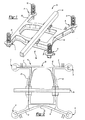
- FIG. 1 illustrates inventive suspension assembly 10.
- Suspension assembly 10 comprises four springs, such as air springs, spaced at locations A, B, C and D.
- Springs 10, 18, 22 and 26, such as air springs, are mounted as known to first plate 30, which is sized to extend to support each spring at locations A, B, C and D.
- plate 30 is of unibody or unitary construction so that stress may be distributed across first plate 30 without the weak points associated with joined pieces.
- second plate 38 Spaced from first plate 30 is second plate 38, which may mirror the size and shape of first plate 30 so as to provide additional support to springs 10, 18, 22 and 26 at locations A, B, C and D, respectively.
- Second plate 38 is also preferably of unibody or unitary form.
- First plate 30 is mounted to second plate 38 by support 42, which is sandwiched between each plate 30, 38.
- Axle 34 is attached to first plate 30 by known techniques.
- Figure 2 illustrates a plan view of suspension assembly 10.
- first plate 30 extends to each location A, B, C and D without the welding seams that are typically found at locations E, F, G and H when lateral tubes and I-beams are employed in known designs.
- First plate 30 may comprise first lateral portion 45 that extends from location A to location C and second lateral portion 43 that extends from location B to location D. Interconnecting these lateral portions 43, 45 to each other are first transverse portion 47 and second transverse portion 40.
- Portions 40, 43, 45 and 47 preferably form a single plate.
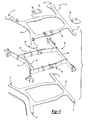
- Figure 3 illustrates an exploded view of the suspension assembly of Figures 1 and 2.
- First plate 30 is spaced from second plate 38.
- support 42 which serves to mount first plate 30 to second plate 38 in a sandwich-like manner.
- Support 42 may comprise webs that extend between first plate 30 and second plate 38.
- web 46 extends along the length of first lateral portion 45 from location A to location C.
- Web 60 may extend along the length of second lateral portion 43 from location B to location D.
- Spaced from web 60 is web 64, which serves as a rear brace that provides additional support to assembly 10.
- web 50 may extend along the length of transverse portion 40 while web 54 may extend along the length of transverse portion 47.
- Webs 46, 50, 54, 60 and 64 may comprise a single piece or multiple pieces that are welded together as known.
- support 42 is attached to first plate 30 and second plate 38 by welding. It is preferable that the welds be located inside of plates 30 and 38 and the oriented parallel to the bending axis of the anticipated load on assembly 10 instead of against it. In this way, welds are not placed at potential locations of cracking.
Landscapes
- Engineering & Computer Science (AREA)
- Mechanical Engineering (AREA)
- Vehicle Body Suspensions (AREA)
- Springs (AREA)
Applications Claiming Priority (2)
| Application Number | Priority Date | Filing Date | Title |
|---|---|---|---|
| US369414 | 2003-02-18 | ||
| US10/369,414 US7070177B2 (en) | 2003-02-18 | 2003-02-18 | Sandwich design of four bag suspension for bus and coach rear drive axles |
Publications (2)
| Publication Number | Publication Date |
|---|---|
| EP1449685A2 true EP1449685A2 (fr) | 2004-08-25 |
| EP1449685A3 EP1449685A3 (fr) | 2005-01-19 |
Family
ID=32736426
Family Applications (1)
| Application Number | Title | Priority Date | Filing Date |
|---|---|---|---|
| EP04250229A Withdrawn EP1449685A3 (fr) | 2003-02-18 | 2004-01-16 | Montage de suspension pour véhicule |
Country Status (3)
| Country | Link |
|---|---|
| US (1) | US7070177B2 (fr) |
| EP (1) | EP1449685A3 (fr) |
| BR (1) | BRPI0400185B1 (fr) |
Cited By (1)
| Publication number | Priority date | Publication date | Assignee | Title |
|---|---|---|---|---|
| WO2016154353A1 (fr) * | 2015-03-26 | 2016-09-29 | Hendrickson Usa, L.L.C. | Suspension de véhicule à quatre sacs |
Families Citing this family (11)
| Publication number | Priority date | Publication date | Assignee | Title |
|---|---|---|---|---|
| DE102004005571B4 (de) * | 2004-02-05 | 2008-07-10 | Daimler Ag | Verbindungsbereich zur Anbindung eines Anbauteils an eine Fahrzeugkarosserie |
| KR100764485B1 (ko) * | 2005-12-12 | 2007-10-08 | 현대자동차주식회사 | 자동차용 서포트 빔 |
| MX2010009035A (es) * | 2008-02-18 | 2011-03-04 | Stemco Lp | Dispositivo para aislar sensores de la vibracion. |
| KR101134763B1 (ko) * | 2010-05-14 | 2012-04-13 | 기아자동차주식회사 | 대형 버스의 리어서스펜션 |
| CN101982329A (zh) * | 2010-11-24 | 2011-03-02 | 力帆实业(集团)股份有限公司 | 轿车发动机悬置与前轮罩前板连接结构 |
| US8807633B2 (en) * | 2011-06-21 | 2014-08-19 | Cnh Industrial America Llc | Cab suspension system for an off-road vehicle |
| US8465036B2 (en) | 2011-08-02 | 2013-06-18 | Arvinmeritor Technology, Llc | Side mounted air spring trailing arm suspension |
| ES2872931T3 (es) * | 2013-12-06 | 2021-11-03 | Itt Mfg Enterprises Llc | Conjunto de aislamiento sísmico |
| EP3177850B1 (fr) | 2014-09-24 | 2019-07-24 | Siemens Aktiengesellschaft | Dispositif de support et d'amortissement pour équipements électriques |
| AT517179A3 (de) * | 2015-04-30 | 2018-03-15 | Siemens Ag Oesterreich | Vorrichtung zur Befestigung von Bremseinrichtungen an einem Fahrwerksrahmen eines Schienenfahrzeuges |
| CN109996417B (zh) * | 2019-02-20 | 2023-10-20 | 和信精密科技(吴江)有限公司 | 一种可拆式server |
Family Cites Families (21)
| Publication number | Priority date | Publication date | Assignee | Title |
|---|---|---|---|---|
| US880025A (en) * | 1905-12-15 | 1908-02-25 | Reinhold Herman | Running-gear or suspension-frame for vehicles. |
| US1495171A (en) * | 1923-04-06 | 1924-05-27 | Fraser John | Chassis for vehicles |
| US1708217A (en) * | 1927-09-29 | 1929-04-09 | Fraser John | Vehicle chassis |
| US2249212A (en) * | 1938-09-30 | 1941-07-15 | Kolbe Joachim | Vehicle body suspension means |
| DE976332C (de) * | 1940-08-02 | 1963-07-04 | Budd Co | Fahrzeugunterrahmen, insbesondere kombinierter Fahrgestell- und Wagenkasten-Unterrahmen |
| US2620742A (en) * | 1947-04-24 | 1952-12-09 | Budd Co | Railway truck |
| US2589043A (en) | 1947-08-06 | 1952-03-11 | William M Brewen | Frame for vehicles |
| US2901266A (en) * | 1954-06-21 | 1959-08-25 | Budd Co | Automobile chassis or underframe structure |
| US3565456A (en) | 1968-12-16 | 1971-02-23 | Motor Coach Ind Ltd | Rear suspension for vehicles |
| DE2256121A1 (de) * | 1972-11-16 | 1974-05-30 | Hamburger Hochbahn Ag | Achsanordnung fuer omnibusse |
| US3912295A (en) * | 1974-03-04 | 1975-10-14 | Budd Co | Crash energy-attenuating means for a vehicle frame construction |
| US4343375A (en) * | 1979-10-22 | 1982-08-10 | Manning Donald L | Vehicle drive wheel suspension |
| DE3030594A1 (de) * | 1980-08-11 | 1982-02-18 | Siemens AG, 1000 Berlin und 8000 München | Triebaggregat fuer die treibachsen von schienenfahrzeugen |
| DE3048754C2 (de) * | 1980-12-23 | 1988-07-07 | Daimler-Benz Ag, 7000 Stuttgart | Achsträger für Kraftfahrzeuge |
| US4941543A (en) * | 1988-12-23 | 1990-07-17 | Dlma Transportation Inc. | Rear wheel suspension and steering system |
| US5012885A (en) * | 1989-03-10 | 1991-05-07 | Dlma Transportation Inc. | Rear wheel suspension and steering system |
| US5188195A (en) * | 1991-11-12 | 1993-02-23 | Haustein Norman E | Vehicle driving wheel suspension system |
| US5749595A (en) * | 1995-02-22 | 1998-05-12 | Jhc Ventures, L.P. | Trailer suspension |
| US5599038A (en) * | 1995-03-14 | 1997-02-04 | German; Mark K. | Method and apparatus for lowering the suspension of a vehicle |
| DE19754427A1 (de) * | 1997-12-08 | 1999-06-17 | Daimler Chrysler Ag | Achsanordnung für eine selbsttragende Kraftfahrzeugkarosserie |
| WO2000047434A1 (fr) * | 1999-02-10 | 2000-08-17 | Erik Zapletal | Systeme de suspension equilibree |
-
2003
- 2003-02-18 US US10/369,414 patent/US7070177B2/en not_active Expired - Fee Related
-
2004
- 2004-01-16 EP EP04250229A patent/EP1449685A3/fr not_active Withdrawn
- 2004-02-11 BR BRPI0400185-0B1A patent/BRPI0400185B1/pt not_active IP Right Cessation
Cited By (1)
| Publication number | Priority date | Publication date | Assignee | Title |
|---|---|---|---|---|
| WO2016154353A1 (fr) * | 2015-03-26 | 2016-09-29 | Hendrickson Usa, L.L.C. | Suspension de véhicule à quatre sacs |
Also Published As
| Publication number | Publication date |
|---|---|
| US20040159995A1 (en) | 2004-08-19 |
| BRPI0400185A (pt) | 2004-12-28 |
| US7070177B2 (en) | 2006-07-04 |
| BRPI0400185B1 (pt) | 2013-07-09 |
| EP1449685A3 (fr) | 2005-01-19 |
Similar Documents
| Publication | Publication Date | Title |
|---|---|---|
| US4386792A (en) | Fabricated load support structural member | |
| US5725247A (en) | End section of frame member | |
| US7144040B2 (en) | Bi-metallic structural component for vehicle frame assembly | |
| US6189930B1 (en) | Joint between side rail and cross member in a vehicle frame assembly | |
| AU2001250043B2 (en) | Aluminum frame hanger for axle/suspension systems | |
| US20070137919A1 (en) | Assembly of a motor vehicle body and a power train and chassis module | |
| EP1449685A2 (fr) | Montage de suspension pour véhicule | |
| US6402172B1 (en) | Suspension frame construction | |
| ITRM970319A1 (it) | Struttura di montaggio per complesso di telaio di veicoli | |
| CA2206650A1 (fr) | Structure de montage pour cadre de vehicule | |
| US20130228993A1 (en) | I-beam axle suspension system | |
| US7980594B2 (en) | Chassis frame especially for a heavy vehicle | |
| EP1077818A1 (fr) | Montage d'ensemble traverse de cadre de remorque de vehicule/suspension | |
| US8006987B2 (en) | Cast trailing arm assembly for trailer suspension | |
| US5393096A (en) | Suspension frame bracket | |
| US10086874B2 (en) | Modular vehicle platform and related methods | |
| EP1447248A2 (fr) | Support pour un ressort à air | |
| US8006990B1 (en) | Spring hanger and method for attachment | |
| US7213825B2 (en) | Leaf spring retaining bracket | |
| US9868329B2 (en) | Spring bracket arm | |
| RU190782U1 (ru) | Рама железнодорожного транспортного средства | |
| EP1440820A2 (fr) | Ensemble de poutre d'essieu avant dirigeable | |
| US6890003B2 (en) | Suspension subframe assembly | |
| CN101263043B (zh) | 轴支架 | |
| US7461865B2 (en) | Aluminum hanger and hanger assembly |
Legal Events
| Date | Code | Title | Description |
|---|---|---|---|
| PUAI | Public reference made under article 153(3) epc to a published international application that has entered the european phase |
Free format text: ORIGINAL CODE: 0009012 |
|
| AK | Designated contracting states |
Kind code of ref document: A2 Designated state(s): AT BE BG CH CY CZ DE DK EE ES FI FR GB GR HU IE IT LI LU MC NL PT RO SE SI SK TR |
|
| AX | Request for extension of the european patent |
Extension state: AL LT LV MK |
|
| PUAL | Search report despatched |
Free format text: ORIGINAL CODE: 0009013 |
|
| AK | Designated contracting states |
Kind code of ref document: A3 Designated state(s): AT BE BG CH CY CZ DE DK EE ES FI FR GB GR HU IE IT LI LU MC NL PT RO SE SI SK TR |
|
| AX | Request for extension of the european patent |
Extension state: AL LT LV MK |
|
| 17P | Request for examination filed |
Effective date: 20050211 |
|
| AKX | Designation fees paid |
Designated state(s): DE FR GB IT SE |
|
| 17Q | First examination report despatched |
Effective date: 20071114 |
|
| STAA | Information on the status of an ep patent application or granted ep patent |
Free format text: STATUS: THE APPLICATION IS DEEMED TO BE WITHDRAWN |
|
| 18D | Application deemed to be withdrawn |
Effective date: 20080326 |