EP1449686A2 - Dispositif de verrouillage d'un essieu oscillant pour véhicules - Google Patents
Dispositif de verrouillage d'un essieu oscillant pour véhicules Download PDFInfo
- Publication number
- EP1449686A2 EP1449686A2 EP04003305A EP04003305A EP1449686A2 EP 1449686 A2 EP1449686 A2 EP 1449686A2 EP 04003305 A EP04003305 A EP 04003305A EP 04003305 A EP04003305 A EP 04003305A EP 1449686 A2 EP1449686 A2 EP 1449686A2
- Authority
- EP
- European Patent Office
- Prior art keywords
- axis
- angle
- chassis
- driving unit
- pendulum
- Prior art date
- Legal status (The legal status is an assumption and is not a legal conclusion. Google has not performed a legal analysis and makes no representation as to the accuracy of the status listed.)
- Granted
Links
- 238000010276 construction Methods 0.000 description 3
- 230000001419 dependent effect Effects 0.000 description 1
- 230000000694 effects Effects 0.000 description 1
Images


Classifications
-
- E—FIXED CONSTRUCTIONS
- E02—HYDRAULIC ENGINEERING; FOUNDATIONS; SOIL SHIFTING
- E02F—DREDGING; SOIL-SHIFTING
- E02F9/00—Component parts of dredgers or soil-shifting machines, not restricted to one of the kinds covered by groups E02F3/00 - E02F7/00
- E02F9/02—Travelling-gear, e.g. associated with slewing gears
- E02F9/028—Travelling-gear, e.g. associated with slewing gears with arrangements for levelling the machine
-
- B—PERFORMING OPERATIONS; TRANSPORTING
- B60—VEHICLES IN GENERAL
- B60G—VEHICLE SUSPENSION ARRANGEMENTS
- B60G17/00—Resilient suspensions having means for adjusting the spring or vibration-damper characteristics, for regulating the distance between a supporting surface and a sprung part of vehicle or for locking suspension during use to meet varying vehicular or surface conditions, e.g. due to speed or load
- B60G17/005—Suspension locking arrangements
-
- B—PERFORMING OPERATIONS; TRANSPORTING
- B60—VEHICLES IN GENERAL
- B60G—VEHICLE SUSPENSION ARRANGEMENTS
- B60G9/00—Resilient suspensions of a rigid axle or axle housing for two or more wheels
- B60G9/02—Resilient suspensions of a rigid axle or axle housing for two or more wheels the axle or housing being pivotally mounted on the vehicle, e.g. the pivotal axis being parallel to the longitudinal axis of the vehicle
-
- B—PERFORMING OPERATIONS; TRANSPORTING
- B60—VEHICLES IN GENERAL
- B60G—VEHICLE SUSPENSION ARRANGEMENTS
- B60G2200/00—Indexing codes relating to suspension types
- B60G2200/30—Rigid axle suspensions
- B60G2200/32—Rigid axle suspensions pivoted
- B60G2200/322—Rigid axle suspensions pivoted with a single pivot point and a straight axle
-
- B—PERFORMING OPERATIONS; TRANSPORTING
- B60—VEHICLES IN GENERAL
- B60G—VEHICLE SUSPENSION ARRANGEMENTS
- B60G2202/00—Indexing codes relating to the type of spring, damper or actuator
- B60G2202/40—Type of actuator
- B60G2202/41—Fluid actuator
-
- B—PERFORMING OPERATIONS; TRANSPORTING
- B60—VEHICLES IN GENERAL
- B60G—VEHICLE SUSPENSION ARRANGEMENTS
- B60G2202/00—Indexing codes relating to the type of spring, damper or actuator
- B60G2202/40—Type of actuator
- B60G2202/41—Fluid actuator
- B60G2202/413—Hydraulic actuator
-
- B—PERFORMING OPERATIONS; TRANSPORTING
- B60—VEHICLES IN GENERAL
- B60G—VEHICLE SUSPENSION ARRANGEMENTS
- B60G2300/00—Indexing codes relating to the type of vehicle
- B60G2300/06—Cranes
Definitions
- the invention relates to a driving unit for vehicles, in particular mobile excavators, with the features of the preamble of claim 1.
- the invention is based on the object of a generic driving unit improve that the hydraulic cylinders are less subject to wear and the driving unit absorbs large forces better despite simple construction.
- the traversing axis and the normal run at an angle to each other, the normal the center of the chassis is inclined closer.
- This angular course of the traversing axis and normal in the non-pivoted position of the pendulum axis leads to a lower one Angle between the traversing axis and the normal in relation to the chassis pivoted position of the pendulum axis.
- the Shear force component reduced that acts on the hydraulic cylinder. If with help force of the hydraulic cylinder between the swing axle and the chassis is to be transferred, the wear on the hydraulic cylinder is significantly reduced Lateral forces significantly reduced.
- the normal the support surface in the non-pivoted position of the pendulum axis at an angle to a vertical axis the pendulum axis can be that which occurs on the hydraulic cylinder Reduce wear effectively.
- the travel axis of the piston rod can be angled run to a vertical axis of the chassis.
- the movement axis of the piston rod and the normal can be particularly preferred the bearing surface in a swivel plane of the pendulum axis between include about 0 ° and 15 °, preferably between about 4 ° and 9 °, especially about 5 ° to 6 °.
- these angular ranges there is a clear reduction in the wide swung out position of the pendulum axis on the shear force component acting on the hydraulic cylinder possible.
- they are in the untilted or to that Chassis pivoted position of the pendulum axis occurring transverse forces low held.
- This has an angular range of approximately 4 ° to 9 °, in particular of about 5 ° to 6 °, found to be particularly ideal and easy to implement.
- Figure 1 shows a view of a front side of a mobile excavator 1 according to a first embodiment, with a driving unit 3 according to the invention of the first embodiment.
- the driving unit 3 can also in this embodiment of the invention be referred to as undercarriage.
- other vehicles with a swing axle such as Mobile cranes, industrial trucks, in particular forklift trucks, equipped with a driving unit according to the invention his.
- the mobile excavator 1 has a vehicle upper part 2, which is driven by the driving unit 3 first embodiment is included.
- the vehicle upper part 2 can in this Embodiment of the invention may also be referred to as superstructure.
- the driving unit 3 has a chassis 4 and a pendulum axis articulated thereon 5, on which wheels 6 are mounted on both sides. Swiveling the pendulum axis 5 takes place around a swivel center 16.
- Hydraulic cylinders 7 are on both sides of the chassis 4 along a travel axis 8 movable piston rods 9 are provided.
- the piston rods 9 are each independent of one another Extendable along the travel axis 8 to the pendulum axis 5.
- the pendulum axis 5 has support elements 11, each of which forms a flat support surface 12. Rounded, in this case spherical cap-shaped, come on the contact surfaces 12 Piston rod ends 10 of the piston rods 9 for contact.
- the pendulum axis 5 is shown in a non-pivoted position.
- the driving unit 3 is in the non-pivoted position Pendulum axis 5 to the vertical axes 13, 14 symmetrically.
- the Driving unit 3 can also be designed asymmetrically.
- the contact surfaces 12 are oriented inclined toward a chassis center 24. Normals 15 of the contact surfaces 12 each run at an angle to the corresponding Vertical axis 13 of the pendulum axis 5. The normals 15, in their illustrated, upper area, a chassis center 24 inclined closer than the respective Traversing axes 8.
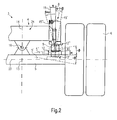
- FIG 2 is a partially enlarged view of a front side of a Driving unit 3 of the first embodiment of the invention shown. The following description refers to that shown in Figure 2 Part of the driving unit 3.
- Pendulum axis indicated in dashed lines.
- the pendulum axis is in a first position 5 'pivoted away from the chassis by a swivel angle - ⁇ and into a second position is the pendulum axis 5 "by a swivel angle + ⁇ to that Chassis 4 pivoted down.
- the swivel angles - ⁇ and + ⁇ have the same absolute amounts. If the pendulum axis 5 'is pivoted away by the swivel angle - ⁇ they are in a position that is pivoted out far relative to the chassis 4.
- the angle of inclination ⁇ has a size in the range between approximately 0 ° and 15 °.
- the angle of inclination ⁇ preferably has values between 4 ° and 9 °, in particular about 5 ° to 6 °.
- Position of the pendulum axis 5 'acting shear force component clearly reduced.
- 5 'occurring transverse forces kept sufficiently low.
- FIG. 3 shows a driving unit 40 of a second embodiment of the invention.
- the driving unit 40 is basically symmetrical.
- the drive unit can also be constructed asymmetrically. The following description relates to the part of the driving unit 40 shown in FIG. 3.
- the driving unit 40 has a chassis 41 on which a pendulum axis 48 is articulated is included.
- the pendulum axis 48 is pivoted about a pivot center 54.
- the pendulum axis 48 has a support element 49 with a support surface 50 on.
- a normal 52 of the contact surface 50 runs parallel to a vertical axis 53 of the pendulum axis 48.
- a hydraulic cylinder 42 which has a piston rod, is provided on the chassis 41 44 has.
- the construction of the hydraulic cylinder 42 itself is analogous to that Hydraulic cylinder 7 of the first embodiment.
- the hydraulic cylinder 42 the driving unit 40 of the second embodiment of the invention angularly on the chassis 41 arranged.
- a travel axis 43 of the piston rod 44 runs in the pivoting plane of the pendulum axis 48 at an angle ⁇ to an angle Edge 46 of the chassis 41.
- the edge 46 runs parallel to a vertical axis 45 of the chassis 41.
- the normal 52 of the bearing surface 50 is accordingly in a non-pivoted state of the pendulum axis 48 by the value of the angle of inclination ⁇ at an angle to the axis of travel 43.
- the upper part shown in Figure 3 the normal 52 runs closer to a chassis center 47 than that Travel axis 43 of the piston rod 44.
- FIG. 3 also shows two pivoted states of the pendulum axis 48 in dashed lines indicated.
- the pendulum axis is in a first swivel position 48 'about the pivot angle - ⁇ pivoted away from the chassis 41 and located himself in a swung out state.
- Pendulum axis 48 In a second swivel position Pendulum axis 48 "pivoted about the pivot angle + ⁇ to the chassis 41 and is therefore in a swiveled-in state.
- the angle of inclination ⁇ by which the axis of travel 43 of the piston rod 44 of the Chassis center 47 pivoted away from the vertical axis 45 of the chassis 41 has a value in the range between approximately 0 ° and 15 °.
- the angle of inclination ⁇ has the value between approximately 4 ° and 9 °, in particular approximately 5 ° up to 6 °.
- the swing-out state of the pendulum axis 48 'transverse forces acting on the hydraulic cylinder 42 are significantly reduced. simultaneously are those in the non-pivoted or swiveled-in state of the pendulum axis 48, 48 "transverse forces are kept low.
- both a travel axis a piston rod in a pivoting plane of a pendulum axis at an angle to a vertical axis of the chassis as well as a normal of a support surface a vertical axis of the pendulum axis.
Landscapes
- Engineering & Computer Science (AREA)
- Mechanical Engineering (AREA)
- Mining & Mineral Resources (AREA)
- Civil Engineering (AREA)
- General Engineering & Computer Science (AREA)
- Structural Engineering (AREA)
- Vehicle Body Suspensions (AREA)
- Transmission Devices (AREA)
- Actuator (AREA)
Applications Claiming Priority (2)
| Application Number | Priority Date | Filing Date | Title |
|---|---|---|---|
| DE20302870U | 2003-02-21 | ||
| DE20302870U DE20302870U1 (de) | 2003-02-21 | 2003-02-21 | Fahreinheit für Fahrzeuge |
Publications (3)
| Publication Number | Publication Date |
|---|---|
| EP1449686A2 true EP1449686A2 (fr) | 2004-08-25 |
| EP1449686A3 EP1449686A3 (fr) | 2004-11-24 |
| EP1449686B1 EP1449686B1 (fr) | 2006-09-20 |
Family
ID=32668181
Family Applications (1)
| Application Number | Title | Priority Date | Filing Date |
|---|---|---|---|
| EP04003305A Expired - Lifetime EP1449686B1 (fr) | 2003-02-21 | 2004-02-13 | Dispositif de verrouillage d'un essieu oscillant pour véhicules |
Country Status (3)
| Country | Link |
|---|---|
| EP (1) | EP1449686B1 (fr) |
| AT (1) | ATE340087T1 (fr) |
| DE (2) | DE20302870U1 (fr) |
Cited By (3)
| Publication number | Priority date | Publication date | Assignee | Title |
|---|---|---|---|---|
| CN103541385A (zh) * | 2013-09-30 | 2014-01-29 | 徐州徐工筑路机械有限公司 | 一种平地机后桥平衡箱锁定机构 |
| EP3213941A1 (fr) | 2016-03-02 | 2017-09-06 | Bucher Hydraulics Erding GmbH | Dispositif de commande d'un arbre oscillant, bloc d'arbre oscillant et machine de travail mobile comprenant au moins un arbre oscillant |
| EP3409514A1 (fr) | 2017-05-30 | 2018-12-05 | Bucher Hydraulics Erding GmbH | Unité de commande, ensemble cylindre et dispositif de commande d'un essieu oscillant pour une machine de travail mobile |
Families Citing this family (2)
| Publication number | Priority date | Publication date | Assignee | Title |
|---|---|---|---|---|
| NL2002109C2 (nl) * | 2008-07-15 | 2010-01-18 | Rene Prinsen Spoorwegmateriale | Rail/weg rupsvoertuig. |
| FI128209B (fi) | 2013-06-14 | 2019-12-31 | Metso Minerals Inc | Menetelmä ja järjestelmä mineraalimateriaalin murskaimen rungon kannattelemiseksi murskauslaitoksen rungolla sekä mineraalimateriaalin prosessointilaitos |
Citations (3)
| Publication number | Priority date | Publication date | Assignee | Title |
|---|---|---|---|---|
| DE1264963B (de) | 1961-11-16 | 1968-03-28 | Oelhydraulik Altenerding Dipl | Einrichtung zur Beeinflussung des Arbeitsmittels von hydraulischen Vorrichtungen |
| DE2625679C2 (de) | 1976-06-08 | 1981-08-27 | Liebherr-Hydraulikbagger Gmbh, 7951 Kirchdorf | Baumaschine, insbesondere Bagger |
| DE2058557C2 (de) | 1970-11-27 | 1983-01-13 | Ölhydraulik Altenerding Dipl.-Ing. Carl Dechamps, 8059 Altenerding | Hydraulische Pendelachs- oder Bodenabstützung eines fahrbaren Baggers oder Krans |
Family Cites Families (6)
| Publication number | Priority date | Publication date | Assignee | Title |
|---|---|---|---|---|
| US2381425A (en) * | 1942-11-10 | 1945-08-07 | Link Belt Speeder Corp | Stabilizer |
| DE1795099U (de) * | 1959-03-11 | 1959-09-03 | Kaspar Lochner | Automatisch-kraftschluessige hydraulische blockiervorrichtung von pendelnd aufgehaengten achsen. |
| US4264014A (en) * | 1978-11-06 | 1981-04-28 | Caterpillar Tractor Co. | Lock out means for pivotal axle suspension cylinders |
| EP0603394B1 (fr) * | 1991-09-09 | 1997-04-23 | Hitachi Construction Machinery Co., Ltd. | Systeme de suspension pour vehicule de chantier |
| US5639119A (en) * | 1992-12-04 | 1997-06-17 | Trak International, Inc. | Forklift stabilizing apparatus |
| JP3780639B2 (ja) * | 1997-06-27 | 2006-05-31 | 株式会社豊田自動織機 | ダンパーの取付構造 |
-
2003
- 2003-02-21 DE DE20302870U patent/DE20302870U1/de not_active Expired - Lifetime
-
2004
- 2004-02-13 AT AT04003305T patent/ATE340087T1/de not_active IP Right Cessation
- 2004-02-13 EP EP04003305A patent/EP1449686B1/fr not_active Expired - Lifetime
- 2004-02-13 DE DE502004001506T patent/DE502004001506D1/de not_active Expired - Lifetime
Patent Citations (3)
| Publication number | Priority date | Publication date | Assignee | Title |
|---|---|---|---|---|
| DE1264963B (de) | 1961-11-16 | 1968-03-28 | Oelhydraulik Altenerding Dipl | Einrichtung zur Beeinflussung des Arbeitsmittels von hydraulischen Vorrichtungen |
| DE2058557C2 (de) | 1970-11-27 | 1983-01-13 | Ölhydraulik Altenerding Dipl.-Ing. Carl Dechamps, 8059 Altenerding | Hydraulische Pendelachs- oder Bodenabstützung eines fahrbaren Baggers oder Krans |
| DE2625679C2 (de) | 1976-06-08 | 1981-08-27 | Liebherr-Hydraulikbagger Gmbh, 7951 Kirchdorf | Baumaschine, insbesondere Bagger |
Cited By (3)
| Publication number | Priority date | Publication date | Assignee | Title |
|---|---|---|---|---|
| CN103541385A (zh) * | 2013-09-30 | 2014-01-29 | 徐州徐工筑路机械有限公司 | 一种平地机后桥平衡箱锁定机构 |
| EP3213941A1 (fr) | 2016-03-02 | 2017-09-06 | Bucher Hydraulics Erding GmbH | Dispositif de commande d'un arbre oscillant, bloc d'arbre oscillant et machine de travail mobile comprenant au moins un arbre oscillant |
| EP3409514A1 (fr) | 2017-05-30 | 2018-12-05 | Bucher Hydraulics Erding GmbH | Unité de commande, ensemble cylindre et dispositif de commande d'un essieu oscillant pour une machine de travail mobile |
Also Published As
| Publication number | Publication date |
|---|---|
| DE502004001506D1 (de) | 2006-11-02 |
| ATE340087T1 (de) | 2006-10-15 |
| DE20302870U1 (de) | 2004-07-01 |
| EP1449686A3 (fr) | 2004-11-24 |
| EP1449686B1 (fr) | 2006-09-20 |
Similar Documents
| Publication | Publication Date | Title |
|---|---|---|
| EP3565778A1 (fr) | Grue permettant la compensation de couples de charge en fonction d'une charge de câble de levage | |
| DE2040687A1 (de) | Teleskopartig ein- und ausfahrbarer Kranausleger mit kastenfoermigen Auslegerteilen | |
| DE3515524C2 (de) | Vorbaugerät für einen Hublader, vorzugsweise Gabelstapler | |
| EP1449686B1 (fr) | Dispositif de verrouillage d'un essieu oscillant pour véhicules | |
| DE19525723A1 (de) | Flurförderzeug mit einem Hubgerüst | |
| DE3149411A1 (de) | Ausleger eines ladebaums fuer das verladen von guetern | |
| DE202006019421U1 (de) | Kranfahrzeug | |
| DE602004012397T2 (de) | Lenkbarer rahmen für ein arbeitsfahrzeug | |
| EP3477018B1 (fr) | Levier creux à deux points | |
| DE7930623U1 (fr) | ||
| EP0333066B1 (fr) | Engin de terrassement, notamment un chargeur | |
| DE3337445A1 (de) | Belastungswaechter mit momentkapazitaetsbegrenzer zur verwendung in einem hydraulikkreis | |
| DE102004042336A1 (de) | Flurförderzeug mit starr mit Lastverlagerungsvorrichtung verbundenem Zylinder | |
| DE102004006179B4 (de) | Laufkatze | |
| DE4331777C2 (de) | Weitwinkel-Schwenkantrieb für den Grundausleger einer Lademaschine | |
| DE3905994C2 (de) | Vorbaugerät mit zwei Greifarmen zum Aufnehmen zylindrischer Körper in horizontaler oder vertikaler Lage mit hydraulischem Antrieb und mit einer Schaltung zur Steuerung derselben | |
| DE2944395C2 (de) | Greif- und Ladevorrichtung | |
| DE202004016639U1 (de) | Mobilkran | |
| DE102004042126A1 (de) | Sicherheitsstütze für Hubzylinder | |
| DE2639621A1 (de) | Stuetzauslegeranordnung fuer einen fahrzeugkran | |
| EP1370732B1 (fr) | Excavateur a roues | |
| EP0006871B1 (fr) | Dispositif de levage et d'abaissement pour basculer une plateforme de chargement, notamment pour camions et remorques | |
| DE10020270B4 (de) | Raupenkran | |
| DE102018105853A1 (de) | Teleradlader | |
| DE202018103212U1 (de) | Vorrichtung zur Sicherung von Traggestellen in einem Innenlader |
Legal Events
| Date | Code | Title | Description |
|---|---|---|---|
| PUAI | Public reference made under article 153(3) epc to a published international application that has entered the european phase |
Free format text: ORIGINAL CODE: 0009012 |
|
| AK | Designated contracting states |
Kind code of ref document: A2 Designated state(s): AT BE BG CH CY CZ DE DK EE ES FI FR GB GR HU IE IT LI LU MC NL PT RO SE SI SK TR |
|
| AX | Request for extension of the european patent |
Extension state: AL LT LV MK |
|
| PUAL | Search report despatched |
Free format text: ORIGINAL CODE: 0009013 |
|
| AK | Designated contracting states |
Kind code of ref document: A3 Designated state(s): AT BE BG CH CY CZ DE DK EE ES FI FR GB GR HU IE IT LI LU MC NL PT RO SE SI SK TR |
|
| AX | Request for extension of the european patent |
Extension state: AL LT LV MK |
|
| RIC1 | Information provided on ipc code assigned before grant |
Ipc: 7B 60G 17/005 B Ipc: 7E 02F 9/22 B Ipc: 7B 60G 9/02 A Ipc: 7B 60B 35/00 B Ipc: 7E 02F 9/02 B |
|
| 17P | Request for examination filed |
Effective date: 20050520 |
|
| AKX | Designation fees paid |
Designated state(s): AT BE BG CH CY CZ DE DK EE ES FI FR GB GR HU IE IT LI LU MC NL PT RO SE SI SK TR |
|
| GRAP | Despatch of communication of intention to grant a patent |
Free format text: ORIGINAL CODE: EPIDOSNIGR1 |
|
| GRAS | Grant fee paid |
Free format text: ORIGINAL CODE: EPIDOSNIGR3 |
|
| GRAA | (expected) grant |
Free format text: ORIGINAL CODE: 0009210 |
|
| AK | Designated contracting states |
Kind code of ref document: B1 Designated state(s): AT BE BG CH CY CZ DE DK EE ES FI FR GB GR HU IE IT LI LU MC NL PT RO SE SI SK TR |
|
| PG25 | Lapsed in a contracting state [announced via postgrant information from national office to epo] |
Ref country code: IT Free format text: LAPSE BECAUSE OF FAILURE TO SUBMIT A TRANSLATION OF THE DESCRIPTION OR TO PAY THE FEE WITHIN THE PRESCRIBED TIME-LIMIT;WARNING: LAPSES OF ITALIAN PATENTS WITH EFFECTIVE DATE BEFORE 2007 MAY HAVE OCCURRED AT ANY TIME BEFORE 2007. THE CORRECT EFFECTIVE DATE MAY BE DIFFERENT FROM THE ONE RECORDED. Effective date: 20060920 Ref country code: FI Free format text: LAPSE BECAUSE OF FAILURE TO SUBMIT A TRANSLATION OF THE DESCRIPTION OR TO PAY THE FEE WITHIN THE PRESCRIBED TIME-LIMIT Effective date: 20060920 Ref country code: SK Free format text: LAPSE BECAUSE OF FAILURE TO SUBMIT A TRANSLATION OF THE DESCRIPTION OR TO PAY THE FEE WITHIN THE PRESCRIBED TIME-LIMIT Effective date: 20060920 Ref country code: SI Free format text: LAPSE BECAUSE OF FAILURE TO SUBMIT A TRANSLATION OF THE DESCRIPTION OR TO PAY THE FEE WITHIN THE PRESCRIBED TIME-LIMIT Effective date: 20060920 Ref country code: IE Free format text: LAPSE BECAUSE OF FAILURE TO SUBMIT A TRANSLATION OF THE DESCRIPTION OR TO PAY THE FEE WITHIN THE PRESCRIBED TIME-LIMIT Effective date: 20060920 Ref country code: CZ Free format text: LAPSE BECAUSE OF FAILURE TO SUBMIT A TRANSLATION OF THE DESCRIPTION OR TO PAY THE FEE WITHIN THE PRESCRIBED TIME-LIMIT Effective date: 20060920 Ref country code: RO Free format text: LAPSE BECAUSE OF FAILURE TO SUBMIT A TRANSLATION OF THE DESCRIPTION OR TO PAY THE FEE WITHIN THE PRESCRIBED TIME-LIMIT Effective date: 20060920 |
|
| REG | Reference to a national code |
Ref country code: GB Ref legal event code: FG4D Free format text: NOT ENGLISH |
|
| REG | Reference to a national code |
Ref country code: CH Ref legal event code: EP |
|
| REG | Reference to a national code |
Ref country code: IE Ref legal event code: FG4D Free format text: LANGUAGE OF EP DOCUMENT: GERMAN |
|
| REF | Corresponds to: |
Ref document number: 502004001506 Country of ref document: DE Date of ref document: 20061102 Kind code of ref document: P |
|
| GBT | Gb: translation of ep patent filed (gb section 77(6)(a)/1977) |
Effective date: 20061109 |
|
| PG25 | Lapsed in a contracting state [announced via postgrant information from national office to epo] |
Ref country code: DK Free format text: LAPSE BECAUSE OF FAILURE TO SUBMIT A TRANSLATION OF THE DESCRIPTION OR TO PAY THE FEE WITHIN THE PRESCRIBED TIME-LIMIT Effective date: 20061220 Ref country code: BG Free format text: LAPSE BECAUSE OF FAILURE TO SUBMIT A TRANSLATION OF THE DESCRIPTION OR TO PAY THE FEE WITHIN THE PRESCRIBED TIME-LIMIT Effective date: 20061220 |
|
| PG25 | Lapsed in a contracting state [announced via postgrant information from national office to epo] |
Ref country code: ES Free format text: LAPSE BECAUSE OF FAILURE TO SUBMIT A TRANSLATION OF THE DESCRIPTION OR TO PAY THE FEE WITHIN THE PRESCRIBED TIME-LIMIT Effective date: 20061231 |
|
| REG | Reference to a national code |
Ref country code: SE Ref legal event code: TRGR |
|
| PGFP | Annual fee paid to national office [announced via postgrant information from national office to epo] |
Ref country code: SE Payment date: 20070212 Year of fee payment: 4 |
|
| PGFP | Annual fee paid to national office [announced via postgrant information from national office to epo] |
Ref country code: BE Payment date: 20070213 Year of fee payment: 4 |
|
| PG25 | Lapsed in a contracting state [announced via postgrant information from national office to epo] |
Ref country code: MC Free format text: LAPSE BECAUSE OF NON-PAYMENT OF DUE FEES Effective date: 20070228 |
|
| PG25 | Lapsed in a contracting state [announced via postgrant information from national office to epo] |
Ref country code: PT Free format text: LAPSE BECAUSE OF FAILURE TO SUBMIT A TRANSLATION OF THE DESCRIPTION OR TO PAY THE FEE WITHIN THE PRESCRIBED TIME-LIMIT Effective date: 20070312 |
|
| ET | Fr: translation filed | ||
| REG | Reference to a national code |
Ref country code: IE Ref legal event code: FD4D |
|
| PLBE | No opposition filed within time limit |
Free format text: ORIGINAL CODE: 0009261 |
|
| STAA | Information on the status of an ep patent application or granted ep patent |
Free format text: STATUS: NO OPPOSITION FILED WITHIN TIME LIMIT |
|
| 26N | No opposition filed |
Effective date: 20070621 |
|
| PG25 | Lapsed in a contracting state [announced via postgrant information from national office to epo] |
Ref country code: GR Free format text: LAPSE BECAUSE OF FAILURE TO SUBMIT A TRANSLATION OF THE DESCRIPTION OR TO PAY THE FEE WITHIN THE PRESCRIBED TIME-LIMIT Effective date: 20061221 |
|
| PG25 | Lapsed in a contracting state [announced via postgrant information from national office to epo] |
Ref country code: AT Free format text: LAPSE BECAUSE OF NON-PAYMENT OF DUE FEES Effective date: 20070213 |
|
| PG25 | Lapsed in a contracting state [announced via postgrant information from national office to epo] |
Ref country code: EE Free format text: LAPSE BECAUSE OF FAILURE TO SUBMIT A TRANSLATION OF THE DESCRIPTION OR TO PAY THE FEE WITHIN THE PRESCRIBED TIME-LIMIT Effective date: 20060920 |
|
| BERE | Be: lapsed |
Owner name: OLHYDRAULIK ALTENERDING *DECHAMPS & KRETZ G.M.B.H. Effective date: 20080228 |
|
| REG | Reference to a national code |
Ref country code: CH Ref legal event code: PL |
|
| EUG | Se: european patent has lapsed | ||
| GBPC | Gb: european patent ceased through non-payment of renewal fee |
Effective date: 20080213 |
|
| PG25 | Lapsed in a contracting state [announced via postgrant information from national office to epo] |
Ref country code: CH Free format text: LAPSE BECAUSE OF NON-PAYMENT OF DUE FEES Effective date: 20080229 Ref country code: LI Free format text: LAPSE BECAUSE OF NON-PAYMENT OF DUE FEES Effective date: 20080229 |
|
| NLV4 | Nl: lapsed or anulled due to non-payment of the annual fee |
Effective date: 20080901 |
|
| PG25 | Lapsed in a contracting state [announced via postgrant information from national office to epo] |
Ref country code: NL Free format text: LAPSE BECAUSE OF NON-PAYMENT OF DUE FEES Effective date: 20080901 |
|
| PG25 | Lapsed in a contracting state [announced via postgrant information from national office to epo] |
Ref country code: SE Free format text: LAPSE BECAUSE OF NON-PAYMENT OF DUE FEES Effective date: 20080214 |
|
| PG25 | Lapsed in a contracting state [announced via postgrant information from national office to epo] |
Ref country code: BE Free format text: LAPSE BECAUSE OF NON-PAYMENT OF DUE FEES Effective date: 20080228 |
|
| PG25 | Lapsed in a contracting state [announced via postgrant information from national office to epo] |
Ref country code: GB Free format text: LAPSE BECAUSE OF NON-PAYMENT OF DUE FEES Effective date: 20080213 |
|
| PG25 | Lapsed in a contracting state [announced via postgrant information from national office to epo] |
Ref country code: CY Free format text: LAPSE BECAUSE OF FAILURE TO SUBMIT A TRANSLATION OF THE DESCRIPTION OR TO PAY THE FEE WITHIN THE PRESCRIBED TIME-LIMIT Effective date: 20060920 Ref country code: LU Free format text: LAPSE BECAUSE OF NON-PAYMENT OF DUE FEES Effective date: 20070213 |
|
| PG25 | Lapsed in a contracting state [announced via postgrant information from national office to epo] |
Ref country code: TR Free format text: LAPSE BECAUSE OF FAILURE TO SUBMIT A TRANSLATION OF THE DESCRIPTION OR TO PAY THE FEE WITHIN THE PRESCRIBED TIME-LIMIT Effective date: 20060920 Ref country code: HU Free format text: LAPSE BECAUSE OF FAILURE TO SUBMIT A TRANSLATION OF THE DESCRIPTION OR TO PAY THE FEE WITHIN THE PRESCRIBED TIME-LIMIT Effective date: 20070321 |
|
| PGFP | Annual fee paid to national office [announced via postgrant information from national office to epo] |
Ref country code: IT Payment date: 20120221 Year of fee payment: 9 |
|
| PGFP | Annual fee paid to national office [announced via postgrant information from national office to epo] |
Ref country code: DE Payment date: 20140225 Year of fee payment: 11 |
|
| PGFP | Annual fee paid to national office [announced via postgrant information from national office to epo] |
Ref country code: FR Payment date: 20140224 Year of fee payment: 11 |
|
| REG | Reference to a national code |
Ref country code: DE Ref legal event code: R119 Ref document number: 502004001506 Country of ref document: DE |
|
| REG | Reference to a national code |
Ref country code: FR Ref legal event code: ST Effective date: 20151030 |
|
| PG25 | Lapsed in a contracting state [announced via postgrant information from national office to epo] |
Ref country code: DE Free format text: LAPSE BECAUSE OF NON-PAYMENT OF DUE FEES Effective date: 20150901 |
|
| PG25 | Lapsed in a contracting state [announced via postgrant information from national office to epo] |
Ref country code: FR Free format text: LAPSE BECAUSE OF NON-PAYMENT OF DUE FEES Effective date: 20150302 |
|
| PG25 | Lapsed in a contracting state [announced via postgrant information from national office to epo] |
Ref country code: IT Free format text: LAPSE BECAUSE OF NON-PAYMENT OF DUE FEES Effective date: 20140213 |