EP1449700A2 - Steuerung des Bremsdrehmoments für ein Hybridfahrzeug - Google Patents
Steuerung des Bremsdrehmoments für ein Hybridfahrzeug Download PDFInfo
- Publication number
- EP1449700A2 EP1449700A2 EP04250771A EP04250771A EP1449700A2 EP 1449700 A2 EP1449700 A2 EP 1449700A2 EP 04250771 A EP04250771 A EP 04250771A EP 04250771 A EP04250771 A EP 04250771A EP 1449700 A2 EP1449700 A2 EP 1449700A2
- Authority
- EP
- European Patent Office
- Prior art keywords
- braking torque
- engine
- wheel
- generator
- section
- Prior art date
- Legal status (The legal status is an assumption and is not a legal conclusion. Google has not performed a legal analysis and makes no representation as to the accuracy of the status listed.)
- Withdrawn
Links
Images


Classifications
-
- B—PERFORMING OPERATIONS; TRANSPORTING
- B60—VEHICLES IN GENERAL
- B60K—ARRANGEMENT OR MOUNTING OF PROPULSION UNITS OR OF TRANSMISSIONS IN VEHICLES; ARRANGEMENT OR MOUNTING OF PLURAL DIVERSE PRIME-MOVERS IN VEHICLES; AUXILIARY DRIVES FOR VEHICLES; INSTRUMENTATION OR DASHBOARDS FOR VEHICLES; ARRANGEMENTS IN CONNECTION WITH COOLING, AIR INTAKE, GAS EXHAUST OR FUEL SUPPLY OF PROPULSION UNITS IN VEHICLES
- B60K6/00—Arrangement or mounting of plural diverse prime-movers for mutual or common propulsion, e.g. hybrid propulsion systems comprising electric motors and internal combustion engines
- B60K6/20—Arrangement or mounting of plural diverse prime-movers for mutual or common propulsion, e.g. hybrid propulsion systems comprising electric motors and internal combustion engines the prime-movers consisting of electric motors and internal combustion engines, e.g. HEVs
- B60K6/42—Arrangement or mounting of plural diverse prime-movers for mutual or common propulsion, e.g. hybrid propulsion systems comprising electric motors and internal combustion engines the prime-movers consisting of electric motors and internal combustion engines, e.g. HEVs characterised by the architecture of the hybrid electric vehicle
- B60K6/44—Series-parallel type
-
- B—PERFORMING OPERATIONS; TRANSPORTING
- B60—VEHICLES IN GENERAL
- B60W—CONJOINT CONTROL OF VEHICLE SUB-UNITS OF DIFFERENT TYPE OR DIFFERENT FUNCTION; CONTROL SYSTEMS SPECIALLY ADAPTED FOR HYBRID VEHICLES; ROAD VEHICLE DRIVE CONTROL SYSTEMS FOR PURPOSES NOT RELATED TO THE CONTROL OF A PARTICULAR SUB-UNIT
- B60W20/00—Control systems specially adapted for hybrid vehicles
- B60W20/10—Controlling the power contribution of each of the prime movers to meet required power demand
- B60W20/11—Controlling the power contribution of each of the prime movers to meet required power demand using model predictive control [MPC] strategies, i.e. control methods based on models predicting performance
-
- A—HUMAN NECESSITIES
- A23—FOODS OR FOODSTUFFS; TREATMENT THEREOF, NOT COVERED BY OTHER CLASSES
- A23L—FOODS, FOODSTUFFS OR NON-ALCOHOLIC BEVERAGES, NOT OTHERWISE PROVIDED FOR; PREPARATION OR TREATMENT THEREOF
- A23L11/00—Pulses, i.e. fruits of leguminous plants, for production of food; Products from legumes; Preparation or treatment thereof
- A23L11/05—Mashed or comminuted pulses or legumes; Products made therefrom
- A23L11/07—Soya beans, e.g. oil-extracted soya bean flakes
-
- A—HUMAN NECESSITIES
- A47—FURNITURE; DOMESTIC ARTICLES OR APPLIANCES; COFFEE MILLS; SPICE MILLS; SUCTION CLEANERS IN GENERAL
- A47J—KITCHEN EQUIPMENT; COFFEE MILLS; SPICE MILLS; APPARATUS FOR MAKING BEVERAGES
- A47J27/00—Cooking-vessels
- A47J27/56—Preventing boiling over, e.g. of milk
-
- A—HUMAN NECESSITIES
- A47—FURNITURE; DOMESTIC ARTICLES OR APPLIANCES; COFFEE MILLS; SPICE MILLS; SUCTION CLEANERS IN GENERAL
- A47J—KITCHEN EQUIPMENT; COFFEE MILLS; SPICE MILLS; APPARATUS FOR MAKING BEVERAGES
- A47J36/00—Parts, details or accessories of cooking-vessels
-
- B—PERFORMING OPERATIONS; TRANSPORTING
- B60—VEHICLES IN GENERAL
- B60K—ARRANGEMENT OR MOUNTING OF PROPULSION UNITS OR OF TRANSMISSIONS IN VEHICLES; ARRANGEMENT OR MOUNTING OF PLURAL DIVERSE PRIME-MOVERS IN VEHICLES; AUXILIARY DRIVES FOR VEHICLES; INSTRUMENTATION OR DASHBOARDS FOR VEHICLES; ARRANGEMENTS IN CONNECTION WITH COOLING, AIR INTAKE, GAS EXHAUST OR FUEL SUPPLY OF PROPULSION UNITS IN VEHICLES
- B60K6/00—Arrangement or mounting of plural diverse prime-movers for mutual or common propulsion, e.g. hybrid propulsion systems comprising electric motors and internal combustion engines
- B60K6/20—Arrangement or mounting of plural diverse prime-movers for mutual or common propulsion, e.g. hybrid propulsion systems comprising electric motors and internal combustion engines the prime-movers consisting of electric motors and internal combustion engines, e.g. HEVs
- B60K6/50—Architecture of the driveline characterised by arrangement or kind of transmission units
- B60K6/52—Driving a plurality of drive axles, e.g. four-wheel drive
-
- B—PERFORMING OPERATIONS; TRANSPORTING
- B60—VEHICLES IN GENERAL
- B60L—PROPULSION OF ELECTRICALLY-PROPELLED VEHICLES; SUPPLYING ELECTRIC POWER FOR AUXILIARY EQUIPMENT OF ELECTRICALLY-PROPELLED VEHICLES; ELECTRODYNAMIC BRAKE SYSTEMS FOR VEHICLES IN GENERAL; MAGNETIC SUSPENSION OR LEVITATION FOR VEHICLES; MONITORING OPERATING VARIABLES OF ELECTRICALLY-PROPELLED VEHICLES; ELECTRIC SAFETY DEVICES FOR ELECTRICALLY-PROPELLED VEHICLES
- B60L7/00—Electrodynamic brake systems for vehicles in general
- B60L7/24—Electrodynamic brake systems for vehicles in general with additional mechanical or electromagnetic braking
- B60L7/26—Controlling the braking effect
-
- B—PERFORMING OPERATIONS; TRANSPORTING
- B60—VEHICLES IN GENERAL
- B60W—CONJOINT CONTROL OF VEHICLE SUB-UNITS OF DIFFERENT TYPE OR DIFFERENT FUNCTION; CONTROL SYSTEMS SPECIALLY ADAPTED FOR HYBRID VEHICLES; ROAD VEHICLE DRIVE CONTROL SYSTEMS FOR PURPOSES NOT RELATED TO THE CONTROL OF A PARTICULAR SUB-UNIT
- B60W10/00—Conjoint control of vehicle sub-units of different type or different function
- B60W10/04—Conjoint control of vehicle sub-units of different type or different function including control of propulsion units
- B60W10/06—Conjoint control of vehicle sub-units of different type or different function including control of propulsion units including control of combustion engines
-
- B—PERFORMING OPERATIONS; TRANSPORTING
- B60—VEHICLES IN GENERAL
- B60W—CONJOINT CONTROL OF VEHICLE SUB-UNITS OF DIFFERENT TYPE OR DIFFERENT FUNCTION; CONTROL SYSTEMS SPECIALLY ADAPTED FOR HYBRID VEHICLES; ROAD VEHICLE DRIVE CONTROL SYSTEMS FOR PURPOSES NOT RELATED TO THE CONTROL OF A PARTICULAR SUB-UNIT
- B60W10/00—Conjoint control of vehicle sub-units of different type or different function
- B60W10/04—Conjoint control of vehicle sub-units of different type or different function including control of propulsion units
- B60W10/08—Conjoint control of vehicle sub-units of different type or different function including control of propulsion units including control of electric propulsion units, e.g. motors or generators
-
- B—PERFORMING OPERATIONS; TRANSPORTING
- B60—VEHICLES IN GENERAL
- B60W—CONJOINT CONTROL OF VEHICLE SUB-UNITS OF DIFFERENT TYPE OR DIFFERENT FUNCTION; CONTROL SYSTEMS SPECIALLY ADAPTED FOR HYBRID VEHICLES; ROAD VEHICLE DRIVE CONTROL SYSTEMS FOR PURPOSES NOT RELATED TO THE CONTROL OF A PARTICULAR SUB-UNIT
- B60W10/00—Conjoint control of vehicle sub-units of different type or different function
- B60W10/18—Conjoint control of vehicle sub-units of different type or different function including control of braking systems
-
- B—PERFORMING OPERATIONS; TRANSPORTING
- B60—VEHICLES IN GENERAL
- B60W—CONJOINT CONTROL OF VEHICLE SUB-UNITS OF DIFFERENT TYPE OR DIFFERENT FUNCTION; CONTROL SYSTEMS SPECIALLY ADAPTED FOR HYBRID VEHICLES; ROAD VEHICLE DRIVE CONTROL SYSTEMS FOR PURPOSES NOT RELATED TO THE CONTROL OF A PARTICULAR SUB-UNIT
- B60W20/00—Control systems specially adapted for hybrid vehicles
-
- A—HUMAN NECESSITIES
- A23—FOODS OR FOODSTUFFS; TREATMENT THEREOF, NOT COVERED BY OTHER CLASSES
- A23C—DAIRY PRODUCTS, e.g. MILK, BUTTER OR CHEESE; MILK OR CHEESE SUBSTITUTES; PREPARATION THEREOF
- A23C11/00—Milk substitutes, e.g. coffee whitener compositions
- A23C11/02—Milk substitutes, e.g. coffee whitener compositions containing at least one non-milk component as source of fats or proteins
- A23C11/10—Milk substitutes, e.g. coffee whitener compositions containing at least one non-milk component as source of fats or proteins containing or not lactose but no other milk components as source of fats, carbohydrates or proteins
- A23C11/103—Milk substitutes, e.g. coffee whitener compositions containing at least one non-milk component as source of fats or proteins containing or not lactose but no other milk components as source of fats, carbohydrates or proteins containing only proteins from pulses, oilseeds or nuts, e.g. nut milk
-
- A—HUMAN NECESSITIES
- A23—FOODS OR FOODSTUFFS; TREATMENT THEREOF, NOT COVERED BY OTHER CLASSES
- A23C—DAIRY PRODUCTS, e.g. MILK, BUTTER OR CHEESE; MILK OR CHEESE SUBSTITUTES; PREPARATION THEREOF
- A23C20/00—Cheese substitutes
- A23C20/02—Cheese substitutes containing neither milk components, nor caseinate, nor lactose, as sources of fats, proteins or carbohydrates
- A23C20/025—Cheese substitutes containing neither milk components, nor caseinate, nor lactose, as sources of fats, proteins or carbohydrates mainly containing proteins from pulses or oilseeds
-
- B—PERFORMING OPERATIONS; TRANSPORTING
- B60—VEHICLES IN GENERAL
- B60K—ARRANGEMENT OR MOUNTING OF PROPULSION UNITS OR OF TRANSMISSIONS IN VEHICLES; ARRANGEMENT OR MOUNTING OF PLURAL DIVERSE PRIME-MOVERS IN VEHICLES; AUXILIARY DRIVES FOR VEHICLES; INSTRUMENTATION OR DASHBOARDS FOR VEHICLES; ARRANGEMENTS IN CONNECTION WITH COOLING, AIR INTAKE, GAS EXHAUST OR FUEL SUPPLY OF PROPULSION UNITS IN VEHICLES
- B60K17/00—Arrangement or mounting of transmissions in vehicles
- B60K17/34—Arrangement or mounting of transmissions in vehicles for driving both front and rear wheels, e.g. four wheel drive vehicles
- B60K17/356—Arrangement or mounting of transmissions in vehicles for driving both front and rear wheels, e.g. four wheel drive vehicles having fluid or electric motor, for driving one or more wheels
-
- B—PERFORMING OPERATIONS; TRANSPORTING
- B60—VEHICLES IN GENERAL
- B60K—ARRANGEMENT OR MOUNTING OF PROPULSION UNITS OR OF TRANSMISSIONS IN VEHICLES; ARRANGEMENT OR MOUNTING OF PLURAL DIVERSE PRIME-MOVERS IN VEHICLES; AUXILIARY DRIVES FOR VEHICLES; INSTRUMENTATION OR DASHBOARDS FOR VEHICLES; ARRANGEMENTS IN CONNECTION WITH COOLING, AIR INTAKE, GAS EXHAUST OR FUEL SUPPLY OF PROPULSION UNITS IN VEHICLES
- B60K23/00—Arrangement or mounting of control devices for vehicle transmissions, or parts thereof, not otherwise provided for
- B60K23/08—Arrangement or mounting of control devices for vehicle transmissions, or parts thereof, not otherwise provided for for changing number of driven wheels, for switching from driving one axle to driving two or more axles
- B60K23/0808—Arrangement or mounting of control devices for vehicle transmissions, or parts thereof, not otherwise provided for for changing number of driven wheels, for switching from driving one axle to driving two or more axles for varying torque distribution between driven axles, e.g. by transfer clutch
-
- B—PERFORMING OPERATIONS; TRANSPORTING
- B60—VEHICLES IN GENERAL
- B60L—PROPULSION OF ELECTRICALLY-PROPELLED VEHICLES; SUPPLYING ELECTRIC POWER FOR AUXILIARY EQUIPMENT OF ELECTRICALLY-PROPELLED VEHICLES; ELECTRODYNAMIC BRAKE SYSTEMS FOR VEHICLES IN GENERAL; MAGNETIC SUSPENSION OR LEVITATION FOR VEHICLES; MONITORING OPERATING VARIABLES OF ELECTRICALLY-PROPELLED VEHICLES; ELECTRIC SAFETY DEVICES FOR ELECTRICALLY-PROPELLED VEHICLES
- B60L2240/00—Control parameters of input or output; Target parameters
- B60L2240/40—Drive Train control parameters
- B60L2240/42—Drive Train control parameters related to electric machines
- B60L2240/423—Torque
-
- B—PERFORMING OPERATIONS; TRANSPORTING
- B60—VEHICLES IN GENERAL
- B60L—PROPULSION OF ELECTRICALLY-PROPELLED VEHICLES; SUPPLYING ELECTRIC POWER FOR AUXILIARY EQUIPMENT OF ELECTRICALLY-PROPELLED VEHICLES; ELECTRODYNAMIC BRAKE SYSTEMS FOR VEHICLES IN GENERAL; MAGNETIC SUSPENSION OR LEVITATION FOR VEHICLES; MONITORING OPERATING VARIABLES OF ELECTRICALLY-PROPELLED VEHICLES; ELECTRIC SAFETY DEVICES FOR ELECTRICALLY-PROPELLED VEHICLES
- B60L2240/00—Control parameters of input or output; Target parameters
- B60L2240/40—Drive Train control parameters
- B60L2240/44—Drive Train control parameters related to combustion engines
- B60L2240/441—Speed
-
- B—PERFORMING OPERATIONS; TRANSPORTING
- B60—VEHICLES IN GENERAL
- B60T—VEHICLE BRAKE CONTROL SYSTEMS OR PARTS THEREOF; BRAKE CONTROL SYSTEMS OR PARTS THEREOF, IN GENERAL; ARRANGEMENT OF BRAKING ELEMENTS ON VEHICLES IN GENERAL; PORTABLE DEVICES FOR PREVENTING UNWANTED MOVEMENT OF VEHICLES; VEHICLE MODIFICATIONS TO FACILITATE COOLING OF BRAKES
- B60T2270/00—Further aspects of brake control systems not otherwise provided for
- B60T2270/60—Regenerative braking
- B60T2270/603—ASR features related thereto
-
- B—PERFORMING OPERATIONS; TRANSPORTING
- B60—VEHICLES IN GENERAL
- B60T—VEHICLE BRAKE CONTROL SYSTEMS OR PARTS THEREOF; BRAKE CONTROL SYSTEMS OR PARTS THEREOF, IN GENERAL; ARRANGEMENT OF BRAKING ELEMENTS ON VEHICLES IN GENERAL; PORTABLE DEVICES FOR PREVENTING UNWANTED MOVEMENT OF VEHICLES; VEHICLE MODIFICATIONS TO FACILITATE COOLING OF BRAKES
- B60T2270/00—Further aspects of brake control systems not otherwise provided for
- B60T2270/60—Regenerative braking
- B60T2270/611—Engine braking features related thereto
-
- B—PERFORMING OPERATIONS; TRANSPORTING
- B60—VEHICLES IN GENERAL
- B60W—CONJOINT CONTROL OF VEHICLE SUB-UNITS OF DIFFERENT TYPE OR DIFFERENT FUNCTION; CONTROL SYSTEMS SPECIALLY ADAPTED FOR HYBRID VEHICLES; ROAD VEHICLE DRIVE CONTROL SYSTEMS FOR PURPOSES NOT RELATED TO THE CONTROL OF A PARTICULAR SUB-UNIT
- B60W2510/00—Input parameters relating to a particular sub-units
- B60W2510/06—Combustion engines, Gas turbines
- B60W2510/0638—Engine speed
-
- B—PERFORMING OPERATIONS; TRANSPORTING
- B60—VEHICLES IN GENERAL
- B60W—CONJOINT CONTROL OF VEHICLE SUB-UNITS OF DIFFERENT TYPE OR DIFFERENT FUNCTION; CONTROL SYSTEMS SPECIALLY ADAPTED FOR HYBRID VEHICLES; ROAD VEHICLE DRIVE CONTROL SYSTEMS FOR PURPOSES NOT RELATED TO THE CONTROL OF A PARTICULAR SUB-UNIT
- B60W2540/00—Input parameters relating to occupants
- B60W2540/10—Accelerator pedal position
-
- B—PERFORMING OPERATIONS; TRANSPORTING
- B60—VEHICLES IN GENERAL
- B60W—CONJOINT CONTROL OF VEHICLE SUB-UNITS OF DIFFERENT TYPE OR DIFFERENT FUNCTION; CONTROL SYSTEMS SPECIALLY ADAPTED FOR HYBRID VEHICLES; ROAD VEHICLE DRIVE CONTROL SYSTEMS FOR PURPOSES NOT RELATED TO THE CONTROL OF A PARTICULAR SUB-UNIT
- B60W2710/00—Output or target parameters relating to a particular sub-units
- B60W2710/06—Combustion engines, Gas turbines
- B60W2710/0666—Engine torque
-
- B—PERFORMING OPERATIONS; TRANSPORTING
- B60—VEHICLES IN GENERAL
- B60W—CONJOINT CONTROL OF VEHICLE SUB-UNITS OF DIFFERENT TYPE OR DIFFERENT FUNCTION; CONTROL SYSTEMS SPECIALLY ADAPTED FOR HYBRID VEHICLES; ROAD VEHICLE DRIVE CONTROL SYSTEMS FOR PURPOSES NOT RELATED TO THE CONTROL OF A PARTICULAR SUB-UNIT
- B60W2710/00—Output or target parameters relating to a particular sub-units
- B60W2710/08—Electric propulsion units
- B60W2710/083—Torque
-
- B—PERFORMING OPERATIONS; TRANSPORTING
- B60—VEHICLES IN GENERAL
- B60Y—INDEXING SCHEME RELATING TO ASPECTS CROSS-CUTTING VEHICLE TECHNOLOGY
- B60Y2300/00—Purposes or special features of road vehicle drive control systems
- B60Y2300/89—Repartition of braking force, e.g. friction braking versus regenerative braking
-
- Y—GENERAL TAGGING OF NEW TECHNOLOGICAL DEVELOPMENTS; GENERAL TAGGING OF CROSS-SECTIONAL TECHNOLOGIES SPANNING OVER SEVERAL SECTIONS OF THE IPC; TECHNICAL SUBJECTS COVERED BY FORMER USPC CROSS-REFERENCE ART COLLECTIONS [XRACs] AND DIGESTS
- Y02—TECHNOLOGIES OR APPLICATIONS FOR MITIGATION OR ADAPTATION AGAINST CLIMATE CHANGE
- Y02T—CLIMATE CHANGE MITIGATION TECHNOLOGIES RELATED TO TRANSPORTATION
- Y02T10/00—Road transport of goods or passengers
- Y02T10/60—Other road transportation technologies with climate change mitigation effect
- Y02T10/62—Hybrid vehicles
-
- Y—GENERAL TAGGING OF NEW TECHNOLOGICAL DEVELOPMENTS; GENERAL TAGGING OF CROSS-SECTIONAL TECHNOLOGIES SPANNING OVER SEVERAL SECTIONS OF THE IPC; TECHNICAL SUBJECTS COVERED BY FORMER USPC CROSS-REFERENCE ART COLLECTIONS [XRACs] AND DIGESTS
- Y02—TECHNOLOGIES OR APPLICATIONS FOR MITIGATION OR ADAPTATION AGAINST CLIMATE CHANGE
- Y02T—CLIMATE CHANGE MITIGATION TECHNOLOGIES RELATED TO TRANSPORTATION
- Y02T10/00—Road transport of goods or passengers
- Y02T10/60—Other road transportation technologies with climate change mitigation effect
- Y02T10/64—Electric machine technologies in electromobility
Definitions
- the present invention relates to a brake control apparatus of a vehicle wherein one of either the front or rear wheels are driven by an engine and the other wheels are connected to a generator capable of regenerative (electrical) braking, and that is ideally suited to a four-wheel drive vehicle such as, for example, one wherein the main drive wheels are driven by an engine, and the subordinate drive wheels can be braked by a generator.
- a four-wheel drive vehicle there is a so-called motor four-wheel drive vehicle wherein one of either the front or rear wheels (referred to herein as the main drive wheels) are driven by an engine, and the other wheels (referred to herein as the subordinate drive wheels) are supplementarily driven by a generator, and wherein, during vehicle deceleration, the generator is regeneratively operated, and that regenerative (electrical) braking torque decelerates the vehicle (e.g., refer to the Japanese Laid Open Patent Application No. 11-240351.
- the present invention focuses on the aforementioned problems, and has an object to provide a brake control apparatus that can prevent the tendency for one of either the front or rear wheels to lock before the other wheels by not applying the large braking torque from the engine braking torque only to the main drive wheels.
- the brake control apparatus of the present invention is basically provided with an engine braking torque computing section and a generator braking torque controlling section.
- the engine braking torque computing section is configured and arranged to compute an engine braking torque of an engine that drives a first wheel.
- the generator braking torque controlling section is configured and arranged to control an electrical braking torque of a generator that is configured and arranged to electrically brake a second wheel so that a first to second target wheel braking torque distribution approaches an ideal braking torque distribution between the first and second wheels based on the engine braking torque computed by the engine braking torque computing section, when the engine applies the engine braking torque to the first wheel.
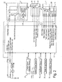
- a four wheel drive vehicle is diagrammatically illustrated that is equipped with a vehicle brake control apparatus in accordance with a first embodiment of the present invention.
- the vehicle in accordance with this embodiment has left and right front wheels 1L and 1R that are driven by an internal combustion engine or main drive source 2, and left and right rear wheels 3L and 3R that are driven by an electric motor or subordinate drive source 4.
- the front wheels 1L and 1R serve as the main drive wheels
- the rear wheels 3L and 3R serve as the subordinate drive wheels, which can be selectively driven by the electric motor 4.
- the engine output torque Te of the internal combustion engine 2 is transferred to the left and right front wheels 1L and 1R through an automatic transmission 30 and a differential gear 31.
- a portion of the engine output torque Te of the internal combustion engine 2 is transferred to a generator 7 that supplies electrical energy to the electric motor 4.
- the engine 2 is operatively attached to the generator 7, which supplies electrical energy to the electric motor 4.
- the generator 7 is directly coupled by a splined joint or the like to a rotary shaft inside the engine 2, such as a camshaft or a crankshaft, or to a gear shaft that rotates both of them.
- the generator 7 rotates at a speed Nh, which is the product of the speed Ne of the engine 2 and a prescribed reduction ratio (or speed increasing ratio).
- the load placed on the internal combustion engine 2 by the generator 7 is used to generate a voltage corresponding to the load torque.
- a four-wheel drive (4WD) controller 8 adjusts the field current Ifh of the generator 7 to control the voltage generated by the load torque.
- the electrical power or voltage generated by the generator 7 can be supplied to the motor 4 via an electric wire 9.
- a junction box 10 is provided an intermediate point in the electric wire 9 between the electric motor 4 and the generator 7.
- a drive shaft of the electric motor 4 is selectively connected to the rear wheels 3L and 3R via a reduction gear 11, a clutch 12,and a differential gear 13.
- the generator 7 in the present embodiment can also be used to supplement the drive torque from the engine 2.
- the electrical power obtained from the motor 4, when the motor 4 is operated regeneratively to function as a generator is supplied to the generator 7, thereby supplementing the drive torque of the engine 2.
- the generator 7 when the motor 4 is operated regeneratively, i.e., when the engine 2 is generating engine braking torque, the generator 7 functions as a motor that drives the engine 2.
- the generator 7 corresponds to a second motor of the present invention.
- the generated torque is also controlled by a field current Imf command value from the 4WD controller 8.
- a main throttle valve 15 is disposed inside the intake passage 14 (e.g., an intake manifold) of the internal combustion engine 2.
- the throttle opening of the main throttle valve 15 is adjusted/controlled in accordance with the amount of depression of the accelerator pedal 17, which also constitutes or functions as an accelerator position or sensor, or a throttle opening instructing device or sensor.
- the throttle valve 15 is not mechanically linked to the depression quantity of the accelerator pedal 17, but is rather a so-called accelerator by wire type, wherein a stepping motor 19 is an actuator, and the throttle opening is adjusted and controlled by the rotational angle corresponding to the step count thereof.
- the depression quantity of the accelerator pedal 17, i.e., the accelerator pedal position Acc 1 is detected by an accelerator pedal sensor 16, and the rotational angle of the stepping motor 19, i.e., the step count, is normally controlled so that the throttle opening is set corresponding to that detected accelerator pedal position Acc 1 .
- the rotational angle of the stepping motor 19 is feedback controlled by a drive signal from a motor controller 20 based on the throttle opening detection value detected by a throttle sensor 22.
- the output torque of the engine 2 can be controlled independent of the operation of the accelerator pedal by the driver.
- a throttle opening command value is output from an engine controller 18 or the 4WD controller 8
- the throttle opening is controlled so that it reaches the throttle opening command value.
- the depression amount detection value or the accelerator pedal position Acc 1 detected by the accelerator sensor 16 is outputted as a control signal to the 4WD controller 8.
- the throttle sensor 22 can also be used to the accelerator pedal position Acc 1 by detecting the throttle opening.
- either the accelerator sensor 16 or the throttle sensor 22 can be considered to constitute a throttle opening determining section.
- the accelerator sensor 16 also constitutes an acceleration instruction sensor.
- the phrase "accelerator position opening degree" as used herein refers to either a throttle opening amount of the main throttle valve 15 or a depression amount of the accelerator pedal 17 or similar accelerator device.
- the phrase “accelerator position opening degree” as used herein refers to either a throttle opening amount of the main throttle valve 15 or a depression amount of the accelerator pedal 17 or similar accelerator device.
- an engine speed sensor 21 is provided that detects the speed of the engine 2, and the engine speed sensor 21 outputs the detected signal to an engine controller 18 and the 4WD controller 8.
- the engine speed sensor 21 constitutes an engine speed detecting section.
- the engine controller 18 controls the operating state of the engine 2 so that it obtains a target rotational torque corresponding to, for example, the depression amount of the accelerator pedal 17 detected by the accelerator pedal sensor 16, i.e., the accelerator pedal position. However, if a prescribed engine torque is demanded by the 4WD controller 8, then the engine controller 18 controls the operating state of the engine by adjusting the throttle opening of the throttle valve 15, so that that engine torque is obtained.
- the transmission 30 is provided with a gear shift position detector or sensor 32 that is configured and arranged to detect the current gear shift range of the transmission 30.
- the shift position detecting sensor 32 is configured and arranged to output or send a detected shift position signal indicative of the current gear range of the transmission 30 to the 4WD controller 8.
- a brake pedal 34 is provided that constitutes a brake instructing/operating section.
- the stroke amount of the brake pedal 34 is detected by a brake stroke sensor 35, which constitutes a brake operation amount sensor outputs the brake stroke amount it detects to a brake controller 36 and the 4WD controller 8.
- the brake controller 36 controls the braking force or torque acting on the vehicle by controlling the braking devices (e.g., disc brakes) 37FL, 37FR, 37RL,and 37RR that are installed on the wheels 1L,1R, 3L,and 3R in response to the inputted brake stroke amount.
- the braking devices e.g., disc brakes
- the generator 7 is equipped with a voltage regulator 22 (regulator) for regulating an output voltage V.
- the 4WD controller 8 controls the generator load torque Th against the internal combustion engine 2 and the generated voltage V by adjusting the field current Ifh such as controlling a generator control command value (duty ratio or field current value).
- the voltage adjuster 22 receives the generator control command value (duty ratio or field current value) from the 4WD controller 8 and adjusts the field current Ifh of the generator 7 to a value corresponding to the generator control command value.
- the voltage adjuster 22 is also capable of detecting the output voltage V of the generator 7 and outputting the detected voltage value to the 4WD controller 8.
- a current sensor 23 is provided inside the junction box 10.
- the current sensor 23 detects the current value Ia of the electrical power supplied from the generator 7 to the electric motor 4 and outputs the detected armature current signal to the 4WD controller 8.
- the voltage value flowing through the electrical line 9 is detected by the 4WD controller 8 to produce a control signal indicative of the voltage across the electric motor 4.
- a relay 24 shuts off or connects the voltage (current) supplied to the electric motor 4 in accordance with a command from the 4WD controller 8.
- a command from the 4WD controller 8 controls the field current Ifm of the electric motor 4 and the adjustment of the field current Ifm adjusts the drive torque Tm.
- the vehicle brake control apparatus is also equipped with a motor rotational speed sensor 26 that detects the rotational speed Nm of the drive shaft of the electric motor 4.
- the motor rotational speed sensor 26 outputs a control signal indicative of the detected rotational speed of the electric motor 4 to the 4WD controller 8.
- the motor rotational speed sensor 26 constitutes an input shaft rotational speed detector or sensor.
- the motor 4 in the present embodiment operates regeneratively, and imparts the braking torque to the rear wheels 3L and 3R.
- the regenerative braking torque from the motor 4 is also controlled by adjustment of the field current Ifm.
- the clutch 12 is a hydraulic clutch or an electromagnetic clutch that connects and disconnects in response to a clutch control command issued from the 4WD controller 8.
- the clutch 12 transmits torque from the electric motor 4 to the rear wheels 3L and 3R at a torque transfer rate corresponding to the clutch control command from the 4WD controller 8.
- the wheels 1L, 1R, 3L, and 3R are provided with wheel speed sensors 27FL, 27FR, 27RL, and 27RR, respectively.
- Each speed sensor 27FL, 27FR, 27RL, and 27RR outputs a pulse signal corresponding to the rotational speed of the respective wheel 1L, 1R, 3L,and 3R to the 4WD controller 8.
- Each of the pulse signals serves as a wheel speed detection value that is indicative of the detected rotational speed of the respective wheel 1L, 1R, 3L,or 3R.
- the wheel speed sensors 27RL and 27RR constitute an output shaft rotational speed detector or sensor.
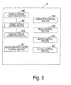
- the 4WD controller 8 is provided with a generator control section 8A, a relay control section 8B, a motor control section 8C, a clutch control section 8D, a surplus torque computing section 8E, a target torque limiting section 8F, a surplus torque converting section 8G, and an engine brake control section 8J.
- the generator control section 8A monitors the generated voltage V of the generator 7 and adjusts the generated voltage V of the generator 7 to the required voltage by adjusting the field current Ifh of the generator 7. Through the voltage regulator 22, the generator control section 8A also reduces the engine braking torque by driving the generator 7 as a motor, while monitoring the generated voltage V of the generator 7.
- the generator control section 8A constitutes the motor generator) drive torque controlling section of the present invention.
- the relay control section 8B controls shutting off and connecting the power supply from the generator 7 to the electric motor 4.
- the relay control section 8B also controls electric power supplied from the motor 4 to the generator 7 when the motor 4 is regeneratively operated and the generator 7 is functioning as a motor to drive the engine 2.
- the motor control section 8C adjusts the torque of the motor 4 to a required value, e.g., to a target motor regenerative braking torque Tbm* computed by calculation processing discussed later, by adjusting the field current Ifm of the motor 4. In other words, the motor control section 8C adjusts the field current Ifm of the electric motor 4 in order to adjust the torque of the electric motor 4 to the required value.
- the motor control section 8C constitutes the generator (motor) braking torque controlling section of the present invention.
- the clutch control section 8D controls the state of the clutch 12 by outputting a clutch control command to the clutch 12. Specifically, when, for example, a target motor regenerative braking torque Tbm* set by the motor control section 8C is greater than or equal to a prescribed motor torque value T TCL (value corresponding to the dead zone), or when there is a clutch engagement request from separate arithmetic processing, then the input side rotational speed and the output side rotational speed of the clutch are matched, and the clutch is engaged when both are rotationally matched. In addition, the clutch is released if, for example, the target motor regenerative braking torque Tbm* falls below the prescribed motor torque value T TCL ⁇
- looped processing is performed in the following sectional sequence: the surplus torque computing section 8E, the target torque limiting section 8F, and the surplus torque converting section 8G.
- the looped sequence is performed at a predetermined sampling interval, and is based on inputted signals.
- the slip speed (acceleration slippage) is computed by, for example, subtracting the average rear wheel speed of the rear wheels 3L and 3R from the average front wheel speed of the front wheels 1L and 1R, computing the absorbed torque needed to suppress acceleration slip of the front wheels 1L, 1R, computing the present load torque of the generator 7, and deriving the surplus torque, i.e., the target generation load torque that should be carried by the generator 7.
- the target torque limiting section 8F it is determined whether the target generation load torque is greater than the maximum load capacity of the generator 7. If, for example, it is determined that the target generation load torque is greater than the maximum load capacity of the generator 7, then the excess torque that exceeds the maximum load capacity is derived, the engine torque upper limit is computed by subtracting the excess torque from the present engine torque, that value is output to the engine controller 18, and the target generation load torque is set to the maximum load capacity.
- the target motor field current is computed in accordance with the speed of the motor 4 detected by the motor speed sensor 26, the target motor field current is output to the motor control section 8C, the induced voltage of the motor 4 is computed from the target motor field current and the speed of the motor 4, the target motor torque is computed based on the generation load torque computed by the surplus torque computing section 8E, the corresponding target armature current is computed using the target motor torque and the target motor field current as variables, the target voltage of the generator 7 is computed from the target armature current, the resistance, and the induced voltage, and the target voltage of the generator 7 is output to the generator control section 8A.
- the front wheels 1L an 1R which are the main drive wheels, undergo acceleration slip due to a small road surface ⁇ or due to the large depression quantity of the accelerator pedal 17 by the driver, then the drive torque transmitted to the front wheels 1L and 1R is adjusted by the generator 7 generating electric power with a generation load torque corresponding to that acceleration slippage. As a result, acceleration slip of the front wheels 1L and 1R, which are the main drive wheels, is suppressed.
- the motor 4 of the four-wheel drive vehicle of the present embodiment is also used to obtain a braking torque by regeneratively operating the motor 4 when the engine braking torque operates as previously discussed. It is the engine braking torque controlling section 8J that functions when the engine braking torque operates.
- the drive torque is treated as a positive value, and the braking torque is treated as a negative value.
- they are treated as torques simply having different directions, and both are treated as positive values (taking the absolute values, or evaluating their magnitudes).
- the engine braking torque controlling section 8J, the target throttle opening Acc 2 *, the target generator field current Ifh, and the target motor field current Ifm are computed for when the engine braking torque operates.
- This arithmetic processing is executed by a timer interrupt processing at a prescribed sampling interval ⁇ T, set on the order of, for example, 10 ms.
- this arithmetic processing is not particularly provided with a step for communication, but the information obtained by the arithmetic processing is updated in memory as needed, and information needed for arithmetic processing is read in from memory as needed, or from another controller.
- the 4WD controller 8 of the brake control apparatus of the present invention is constituted so that it sets the braking torques of the front and rear wheels 1L, 1R, 3L,and 3R by distributing the engine braking torque so that it is made an ideal braking torque distribution, and performs control so that that braking torque matches the electrical braking torque from the generator/motor 4. Consequently, the braking torques of the front and rear wheels 1L, 1R, 3L,and 3R approach the ideal braking torque distribution, even if only the engine braking torque acts upon only one of either the rear or front wheels.
- the brake control apparatus of the present invention is constituted so that it prevents the tendency for only one of either the front or rear wheels to lock before the other wheels.
- step S0 the 4WD controller 8 first determines whether the vehicle state is presently in a four-wheel drive state. If the vehicle is in a four-wheel drive state, then processing proceeds to step S1, otherwise processing returns to the main program.
- step S1 the accelerator pedal position Acc 1 detected by the accelerator pedal sensor 16 is read in by the 4WD controller 8.
- step S2 where the engine speed Ne detected by the engine speed sensor 21 is read in by the 4WD controller 8.
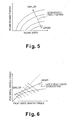
- step S3 processing proceeds to step S3, where the engine braking torque Tbe corresponding to the engine speed Ne and the accelerator pedal position Acc 1 is computed by the 4WD controller 8 from, for example, the control map shown in Figure 5.
- step S4 the 4WD controller 8 determines whether the friction state between the wheels and the road surface is in a low-friction state by using, for example, the operation of the windshield wipers, or the detection of acceleration slip of the front wheels 1L and 1R, which are the main drive wheels, by the immediately preceding arithmetic processing. If the friction state between the wheels and the road surface is a low-friction state, then processing proceeds to step S5. Otherwise, processing proceeds to step S20. Furthermore, any other method would also be acceptable for the technique for detecting whether the friction state between the wheels and the road surface is a low friction state.
- step S5 because, for example, the present state is a two-wheel drive state, the vehicle body deceleration G is computed from the time derivative of the average rear wheel speed detected by the wheel speed sensors 27RL and 27RR of the rear wheels 3L and 3R, which are the subordinate drive wheels. Processing subsequently proceeds to step S6.
- step S6 the ideal braking force distribution (easier to understand if thought of as a ratio) of the front and rear wheels 1L and 1R is derived in accordance with the vehicle body deceleration G computed in the previous step S5, in accordance with, for example, the ideal braking torque distribution map shown in Figure 6.
- the engine braking torque Tbe computed in step S3 is distributed between the front and rear wheels.
- the target front wheel braking torque Tbf* and the target rear wheel braking torque (in this case, the target motor regenerative braking torque Tbm*) for the corresponding to the ideal braking torque distribution are thereby calculated, for example, using the ideal braking torque distribution map shown in Figure 6. Processing by the 4WD controller 8 then proceeds to step S7.
- step S7 the standard throttle opening Acc 20 * needed to achieve the target front wheel braking torque Tbf* is computed by the 4WD controller 8, and processing then proceeds to step S8.
- step S8 the 4WD controller 8 determines whether the standard throttle opening Acc 20 * computed in step S7 is greater than or equal to the maximum throttle opening Acc MAX of the throttle valve 15. Namely, the 4WD controller 8 determines whether the target front wheel braking torque Tbf* can be achieved by controlling the throttle opening. If the standard throttle opening Acc 20 * is greater than or equal to the maximum throttle opening Acc MAX , then processing proceeds to step S9. Otherwise, processing proceeds to step S13.
- step S9 the maximum throttle opening Acc MAX is set to the target throttle opening Acc 2 *, and processing then proceeds to step S10.
- step S10 the value calculated by subtracting the maximum engine braking torque T ACCMAX , corresponding to the maximum throttle opening Acc MAX , from the target front wheel braking torque Tbf*, is assigned as the target generator drive torque Th*. Processing then proceeds to step S11.
- step S13 the standard throttle opening Acc 20 * computed in step S7 is set to the target throttle opening Acc 2 *, and processing then proceeds to step S15.
- step S15 the target generator drive torque Th* is set to zero, and processing then proceeds to step S11.
- step S11 the target generator field current Ifh to achieve the target generator drive torque Th* is computed by the 4WD controller 8. Processing then proceeds to step S16.
- step S16 the target motor field current Ifm to achieve the target motor regenerative braking torque Tbm* is computed by the 4WD controller 8, and processing then proceeds to step S17.
- step S17 the target throttle opening Acc 2 * set in step S9 or step S13 is output to the motor controller 20, the target generator field current Ifh computed in step S11 is output to the generator control section 8A, the target motor field current Ifm computed in step S16 is output to the motor control section 8C, and processing then returns to the main program.
- step S20 the 4WD controller 8 determines whether the engine braking torque Tbe computed in step S3 is less than the present generatable maximum motor regenerative braking torque Tbm MAX . If the engine braking torque Tbe is less than the maximum motor regenerative braking torque Tbm MAX , then processing proceeds to step S21. Otherwise processing proceeds to step S24.
- step S21 the engine braking torque Tbe is set as the target motor regenerative braking torque Tbm*, and processing then proceeds to step S22.
- step S22 the target engine braking torque Tbe* is set to zero, and processing then proceeds to step S23.
- step S24 the maximum motor regenerative braking torque Thm MAX is set as the target motor regenerative braking torque Tbm*, and processing then proceeds to step S25.
- step S25 the target engine braking torque Tbe* is set to a value computed by subtracting the maximum motor regenerative braking torque Thm MAX from the engine braking torque Tbe, and processing then proceeds to step S23.
- step S23 the target throttle opening Acc 2 * that achieves the target engine braking torque Tbe* is computed, and processing proceeds to step S26.
- step S26 the target motor field current Ifm that achieves the target motor regenerative braking torque Tbm* set in step S21 or step S24 is computed, and processing then proceeds to step S27.
- step S27 the target throttle opening Acc 2 * set in step S22 or step S25 is output to the motor controller 20, the target motor field current Ifm computed in step S26 is output to the motor control section 8C, and processing then returns to the main program.
- the engine braking torque Tbe is derived from the engine speed Ne and the accelerator pedal position Acc 1 . If the friction state between the wheels and the road surface is determined to be a low-friction state, then motor regenerative braking is performed so that the braking torque distribution between the front and rear wheels is made to approach the ideal braking torque distribution that avoids locking of the wheels.
- the target motor regenerative braking torque Tbm* is computed as a function of the target front wheel braking torque Tbf* and the target rear wheel braking torque so that the sum of the front wheel engine braking torque and the rear wheel regenerative braking torque matches the original engine braking torque Tbe.
- the standard throttle opening Acc 20 * that achieves the target front wheel braking torque Tbf* is less than the maximum throttle opening Acc MAX , then the standard throttle opening Acc 20 * is set to the target throttle opening Acc 2 *, the target generator drive torque Th* is set to zero, and the target motor field current Ifm and the target throttle opening Acc 2 * that achieve the target motor regenerative braking torque Tbm* are output.
- the braking torque of the front wheels 1L and 1R from the engine braking torque of the engine 2 is reduced by up to the target front wheel braking torque Tbf*, when the motor 4 is regeneratively operated.
- the target motor regenerative braking torque Tbm* acts upon the rear wheels 3L and 3R so that the braking torque distribution of the front and rear wheels is made to approach the ideal braking torque distribution. Consequently, the tendency for one of either the front or rear wheels to lock can be prevented even on road surfaces in a low-friction state.
- the target front wheel braking torque Tbf* and the target rear wheel braking torque i.e., the target motor regenerative braking torque Tbm*
- matches the engine braking torque Tbe in the accelerator pedal release state there is no discomfort because it matches the deceleration in the accelerator pedal release state.
- the maximum throttle opening Acc MAX is set to the target throttle opening Acc 2 *, but the target generator drive torque Th* is set to the value obtained by subtracting the maximum engine braking torque T AccMAX corresponding to the maximum throttle opening Acc MAX from the target front wheel braking torque Tbf*, and the target generator field current Ifh that achieves the target generator drive torque Th* is output to the generator control section 8A.
- the target front wheel braking torque Tbf* cannot be achieved by simply adjusting the throttle opening of the throttle valve 15, then that torque shortfall, i.e., the drive torque in this case, is added to the engine 2 by the generator 7.
- the braking torque that acts upon the front wheels 1L and 1R from the engine 2 is thereby decreased due to the addition of the drive torque from the generator 7.
- the braking torque distribution of the front and rear wheels more definitively approaches the ideal braking torque distribution, and vehicle safety can thereby be much more reliably maintained.
- the electrical power obtained by regeneratively operating the motor 4 can directly drive the generator 7, thus not wasting the electrical power.
- Controlling the engine braking torque in this manner is a control mode that is possible only in a vehicle in which one of either the front or rear wheels is driven by the engine and the other wheels can be regeneratively braked by a motor. Even in a typical hybrid vehicle, control is performed by, for example, opening the throttle valve and reducing the engine braking torque, but reducing the engine braking torque increases the motor regenerative braking torque, with the object to increase the amount that the battery is charged, and is not for the purpose of balancing the braking torque of the front and rear wheels so as to approach the ideal braking torque.
- the retarder installed on vehicles equipped with large displacement diesel engines is provided on main drive wheels, i.e., the wheels which the engine braking torque acts upon, and therefore does not distribute the overall braking torque corresponding to the engine braking torque to the front and rear wheels.
- the engine braking torque The is compared with the maximum regenerative braking torque Tbm MAX . If the engine braking torque Tbe is less than the maximum regenerative braking torque Tbm MAX , then the value of engine braking torque The is set to the target motor regenerative braking torque Tbm* without any adjustments, and the target engine braking torque Tbe* is set to zero.
- the maximum regenerative braking torque Tbm MAX is set to the target motor regenerative braking torque Tbm*, and the target engine braking torque Tbe* is set to the value computed by subtracting the maximum regenerative braking torque Tbm MAX from the engine braking torque Tbe.
- the portion of the engine braking torque that is supplemented by the regenerative braking torque is completely transferred to regenerative braking, and the regenerative braking acts in place of a part or all of the engine braking torque. Consequently, this control improves the kinetic energy recovery efficiency. Furthermore, this control does not tend to lock one of either the front or rear wheels because it is performed when the friction state between the wheels and the road surface is not a low friction state, as described earlier.
- the arithmetic processing in steps S1 through S3 shown in Figure 4 constitutes the engine braking torque computing section of the present invention.
- the arithmetic processing of step S6 in Figure 4 constitutes the braking torque distributing section.
- the engine controller 18 in Figure 1 and the arithmetic processing in steps S7 through S9, S13,and S17 in Figure 4 constitute the engine braking torque controlling section.
- the motor controller section 8C in Figure 3 and the arithmetic processing in steps S16, S17, S21, S24, S26, and S27 in Figure 4 constitute the generator (motor) braking torque controlling section.
- the generator control section 8A in Figure 3 and the arithmetic processing in steps S11 and S17 in Figure 4 constitute the motor (generator) drive torque controlling section.
- the arithmetic processing in step S4 in Figure 4 constitutes the low road surface friction state detecting section.
- the electrical braking of the present invention adds to the regenerative braking, as discussed earlier, and includes the case in which the electrical generation load from the generator 7 front-rear wheel braking distribution is used in braking.
- the abovementioned embodiment illustrates the case of a four wheel drive vehicle, but is also applicable to a two-wheel drive vehicle that uses the motor 4 as a drive source.
- the generator 7 it is also acceptable for the generator 7 to be coupled to the engine 2 by a belt or chain and the like. However, it is necessary in that case to take into consideration stretching and slipping of the belt or chain.
- the abovementioned embodiment is arranged so that the actual front-rear wheel braking distribution approximately matches the ideal front-rear wheel braking distribution. However, as long as it approaches the ideal front-rear wheel braking distribution, it is acceptable even if the actual front-rear wheel braking distribution does not necessarily match the ideal front-rear wheel braking distribution.
- the regenerative braking torque can also simply be added so that the ideal braking torque distribution corresponding to the regularly generated engine braking is obtained.
- a mode is also acceptable wherein the engine drives the rear wheels.
Landscapes
- Engineering & Computer Science (AREA)
- Chemical & Material Sciences (AREA)
- Combustion & Propulsion (AREA)
- Transportation (AREA)
- Mechanical Engineering (AREA)
- Food Science & Technology (AREA)
- Automation & Control Theory (AREA)
- Electromagnetism (AREA)
- Life Sciences & Earth Sciences (AREA)
- Physics & Mathematics (AREA)
- Power Engineering (AREA)
- Botany (AREA)
- Nutrition Science (AREA)
- Health & Medical Sciences (AREA)
- Polymers & Plastics (AREA)
- Agronomy & Crop Science (AREA)
- Electric Propulsion And Braking For Vehicles (AREA)
- Hybrid Electric Vehicles (AREA)
- Arrangement And Driving Of Transmission Devices (AREA)
- Arrangement Of Transmissions (AREA)
- Regulating Braking Force (AREA)
Applications Claiming Priority (4)
| Application Number | Priority Date | Filing Date | Title |
|---|---|---|---|
| JP2003039168 | 2003-02-18 | ||
| JP2003039168 | 2003-02-18 | ||
| JP2003399507 | 2003-11-28 | ||
| JP2003399507A JP2004268901A (ja) | 2003-02-18 | 2003-11-28 | 制動制御装置 |
Publications (2)
| Publication Number | Publication Date |
|---|---|
| EP1449700A2 true EP1449700A2 (de) | 2004-08-25 |
| EP1449700A3 EP1449700A3 (de) | 2006-05-10 |
Family
ID=32737729
Family Applications (1)
| Application Number | Title | Priority Date | Filing Date |
|---|---|---|---|
| EP04250771A Withdrawn EP1449700A3 (de) | 2003-02-18 | 2004-02-12 | Steuerung des Bremsdrehmoments für ein Hybridfahrzeug |
Country Status (5)
| Country | Link |
|---|---|
| US (1) | US7001306B2 (de) |
| EP (1) | EP1449700A3 (de) |
| JP (1) | JP2004268901A (de) |
| KR (1) | KR20040074946A (de) |
| CN (1) | CN1522911A (de) |
Cited By (6)
| Publication number | Priority date | Publication date | Assignee | Title |
|---|---|---|---|---|
| EP1555184A3 (de) * | 2004-01-15 | 2006-04-26 | Nissan Motor Co., Ltd. | Bremsregelvorrichtung für Kraftfahrzeuge |
| WO2007074120A1 (de) * | 2005-12-29 | 2007-07-05 | Robert Bosch Gmbh | Verfahren zur überwachung negativer momente bei hybridfahrzeugen |
| WO2007091144A3 (en) * | 2006-02-08 | 2007-10-18 | Toyota Motor Co Ltd | Control apparatus and control method for vehicle |
| FR2907380A1 (fr) * | 2006-10-20 | 2008-04-25 | Peugeot Citroen Automobiles Sa | Vehicule hybride et son procede de pilotage. |
| WO2009144064A1 (de) * | 2008-05-26 | 2009-12-03 | Robert Bosch Gmbh | Verfahren zum regeln eines schleppmomentes eines elektromotorisch angetriebenen kraftfahrzeuges unter berücksichtigung des auf der fahrbahnoberfläche vorliegenden reibwertes und vorrichtung zum durchführen eines solchen verfahrens |
| US20210070266A1 (en) * | 2019-09-09 | 2021-03-11 | Toyota Jidosha Kabushiki Kaisha | Electric vehicle and method for controlling electric vehicle |
Families Citing this family (54)
| Publication number | Priority date | Publication date | Assignee | Title |
|---|---|---|---|---|
| JP4376589B2 (ja) * | 2003-10-29 | 2009-12-02 | 日産自動車株式会社 | 四輪駆動車両 |
| US7222013B2 (en) * | 2004-02-14 | 2007-05-22 | General Motors Corporation | Throttle phase out control |
| US8380416B2 (en) * | 2004-03-18 | 2013-02-19 | Ford Global Technologies | Method and apparatus for controlling brake-steer in an automotive vehicle in reverse |
| US7131708B2 (en) * | 2004-05-14 | 2006-11-07 | General Motors Corporation | Coordinated regenerative and engine retard braking for a hybrid vehicle |
| US7163487B2 (en) * | 2004-05-14 | 2007-01-16 | General Motors Corporation | Engine retard operation scheduling and management in a hybrid vehicle |
| US7493205B2 (en) * | 2004-06-17 | 2009-02-17 | Caterpillar Inc. | Brake control system for an electric drive vehicle |
| GB0515105D0 (en) * | 2004-08-02 | 2005-08-31 | Ford Global Tech Llc | System and method for braking a vehicle |
| JP4002279B2 (ja) * | 2005-06-27 | 2007-10-31 | 本田技研工業株式会社 | 車両のトラクション制御装置 |
| JP2007085405A (ja) * | 2005-09-20 | 2007-04-05 | Kobelco Cranes Co Ltd | 油圧駆動式作業車両の走行安定装置 |
| JP4265592B2 (ja) * | 2005-10-05 | 2009-05-20 | トヨタ自動車株式会社 | 車両の減速制御装置 |
| US20070179681A1 (en) * | 2006-01-31 | 2007-08-02 | Ford Global Technologies, Llc | System and method for operating a vehicle |
| JP4776435B2 (ja) * | 2006-05-24 | 2011-09-21 | 本田技研工業株式会社 | 自走式作業機の走行駆動機構 |
| EP2084043B1 (de) * | 2006-11-29 | 2015-01-14 | Continental Teves AG & Co. oHG | Vorrichtung zur bestimmung eines fahrzustandes und verfahren zum fahrzustandabhängigen betrieb einer kombinierten fahrzeugbremsanlage |
| JP5187479B2 (ja) * | 2007-02-22 | 2013-04-24 | 株式会社アドヴィックス | 車両挙動制御装置 |
| JP4974766B2 (ja) * | 2007-05-30 | 2012-07-11 | 本田技研工業株式会社 | 車両用ブレーキ液圧制御装置 |
| JP5064920B2 (ja) * | 2007-07-20 | 2012-10-31 | トヨタ自動車株式会社 | 車輌の制動装置 |
| KR100946492B1 (ko) | 2007-10-29 | 2010-03-10 | 현대자동차주식회사 | 4륜 구동 하이브리드 차량의 후륜 구동장치 |
| US8793002B2 (en) * | 2008-06-20 | 2014-07-29 | Caterpillar Inc. | Torque load control system and method |
| ES2429105T3 (es) * | 2008-05-27 | 2013-11-13 | Iveco S.P.A. | Método y dispositivo de frenado con recuperación energética en particular para un vehículo equipado con sistema de tracción híbrida |
| US8214113B2 (en) * | 2008-06-30 | 2012-07-03 | Caterpillar Inc. | Retarding system that retards motion of power source |
| EP2172378B1 (de) | 2008-10-06 | 2019-07-03 | Volvo Car Corporation | Verfahren und Vorrichtung zum regenerativen Bremsen in einem Fahrzeug |
| US8924120B2 (en) * | 2009-06-06 | 2014-12-30 | Ford Global Technologies, Llc | Regenerative brake control system and method |
| KR101048142B1 (ko) * | 2009-10-23 | 2011-07-08 | 기아자동차주식회사 | 하이브리드 차량의 회생제동토크 제어장치 및 방법 |
| KR101048149B1 (ko) * | 2009-11-17 | 2011-07-08 | 기아자동차주식회사 | 하이브리드 차량의 회생제동토크 보상장치 및 방법 |
| WO2011117994A1 (ja) * | 2010-03-25 | 2011-09-29 | トヨタ自動車株式会社 | 車両の回生制御システム |
| DE102011076640A1 (de) | 2010-09-14 | 2012-03-15 | Robert Bosch Gmbh | Verfahren zur Bremsmomentenregelung in einem Zweiradfahrzeug bei Schräglagenfahrt |
| DE102010062947A1 (de) * | 2010-12-13 | 2012-06-14 | Zf Friedrichshafen Ag | Verfahren zur Ansteuerung eines Retarders eines Kraftfahrzeuges |
| CN102390271A (zh) * | 2011-08-29 | 2012-03-28 | 徐工集团工程机械股份有限公司江苏徐州工程机械研究院 | 一种电动轮矿用卡车反拖动制动方法 |
| CN102505622A (zh) * | 2011-10-10 | 2012-06-20 | 同济大学 | 基于fwd无损检测路面状况的方法 |
| US9650036B2 (en) | 2012-05-04 | 2017-05-16 | Ford Global Technologies, Llc | Methods and systems for adjusting cylinder air charge |
| US8813881B2 (en) | 2012-05-04 | 2014-08-26 | Ford Global Technologies, Llc | Methods and systems for a vehicle driveline power take off |
| US9656665B2 (en) | 2012-05-04 | 2017-05-23 | Ford Global Technologies, Llc | Methods and systems for a driveline dual mass flywheel |
| US8998771B2 (en) | 2012-05-04 | 2015-04-07 | Ford Global Technologies, Llc | Methods and systems for a vehicle driveline |
| US9827975B2 (en) | 2012-05-04 | 2017-11-28 | Ford Global Technologies, Llc | Methods and systems for improving transmission shifting |
| KR101405754B1 (ko) | 2012-09-07 | 2014-06-10 | 성균관대학교산학협력단 | 노면 조건을 고려한 차량의 제동 제어 방법 |
| CN103723141B (zh) * | 2012-10-15 | 2018-04-13 | 福特环球技术公司 | 用于变化的行驶状况期间车辆传动系控制的方法和系统 |
| KR20140079156A (ko) * | 2012-12-18 | 2014-06-26 | 현대자동차주식회사 | 하이브리드 차량의 모터의 토크 결정 방법 및 시스템 |
| CN105683009B (zh) * | 2013-11-08 | 2018-01-26 | 本田技研工业株式会社 | 制动力控制系统 |
| US9358890B2 (en) * | 2014-01-17 | 2016-06-07 | Ford Global Technologies, Llc | Hybrid vehicle braking system and method |
| CN103935251B (zh) * | 2014-04-30 | 2016-06-29 | 杭州明果教育咨询有限公司 | 一种电动汽车制动时最大能量回收的控制方法 |
| CN104631292B (zh) * | 2014-12-17 | 2016-05-04 | 山西省交通科学研究院 | 一种基于双后轴检测车的路基回弹模量测试方法 |
| DE102015209245A1 (de) | 2015-05-20 | 2016-11-24 | Avl Commercial Driveline & Tractor Engineering Gmbh | Verfahren zum Betrieb eines Fahrzeuggespanns, Fahrzeuggespann, Zugfahrzeug und Arbeitsgerät |
| CN106427601B (zh) | 2015-08-11 | 2019-02-26 | 比亚迪股份有限公司 | 基于四轮驱动的电动汽车的制动系统及方法及电动汽车 |
| KR20170029344A (ko) * | 2015-09-07 | 2017-03-15 | 현대자동차주식회사 | 회생제동 협조제어시 제동력 제어방법 |
| DE102015223504A1 (de) * | 2015-11-27 | 2017-06-01 | Robert Bosch Gmbh | Verfahren und Vorrichtung zum Betreiben eines Kraftfahrzeugs |
| EP3406499B1 (de) * | 2016-03-30 | 2020-02-12 | Komatsu Ltd. | Hybrides arbeitsfahrzeug und verfahren zur steuerung des hybriden arbeitsfahrzeugs |
| US10513265B2 (en) * | 2017-03-13 | 2019-12-24 | Ford Global Technologies, Llc | Methods and system for hybrid vehicle regenerative braking |
| US20220194232A1 (en) * | 2019-05-06 | 2022-06-23 | Aikar Technology Inc. | A vehicle braking method and system |
| JP2021017194A (ja) * | 2019-07-23 | 2021-02-15 | トヨタ自動車株式会社 | 操作部制御装置及び車両制御システム |
| CN110562227B (zh) * | 2019-08-22 | 2021-04-02 | 中国第一汽车股份有限公司 | 一种电液耦合制动系统及车辆 |
| KR102885166B1 (ko) * | 2019-10-29 | 2025-11-18 | 현대자동차주식회사 | 친환경 자동차 및 그를 위한 제동 제어 보정 방법 |
| GB2598151B (en) * | 2020-08-21 | 2022-11-09 | Jaguar Land Rover Ltd | A control system for controlling torque distribution |
| KR102845700B1 (ko) * | 2020-12-07 | 2025-08-12 | 현대자동차주식회사 | 전기차의 제동 제어 방법 |
| DE102021208582A1 (de) * | 2021-08-06 | 2023-02-09 | Robert Bosch Gesellschaft mit beschränkter Haftung | Verfahren zum Betreiben eines Bremsunterstützungssystems für ein Elektromotorrad |
Family Cites Families (13)
| Publication number | Priority date | Publication date | Assignee | Title |
|---|---|---|---|---|
| JPH05161216A (ja) * | 1991-12-05 | 1993-06-25 | Honda Motor Co Ltd | 電動車両の変速制御装置 |
| JP3189981B2 (ja) * | 1991-12-05 | 2001-07-16 | 本田技研工業株式会社 | 電動車両の制動装置 |
| JPH1118208A (ja) | 1997-06-19 | 1999-01-22 | Toyota Motor Corp | 車 輌 |
| JP3683405B2 (ja) | 1998-02-24 | 2005-08-17 | 本田技研工業株式会社 | 車両の発進アシスト装置 |
| DE19810656A1 (de) * | 1998-03-12 | 1999-09-16 | Itt Mfg Enterprises Inc | Verfahren und Vorrichtung zum statischen oder dynamischen Ermitteln von Sollwerten für Bremskräfte oder Bremsmomente |
| WO1999056011A1 (fr) * | 1998-04-28 | 1999-11-04 | Hitachi, Ltd. | Voiture hybride, et procede et dispositif d'entrainement pour ladite voiture |
| JP2000094979A (ja) * | 1998-09-28 | 2000-04-04 | Hitachi Ltd | ハイブリッド車両の駆動方法 |
| JP3763231B2 (ja) | 1999-06-04 | 2006-04-05 | トヨタ自動車株式会社 | 制動装置 |
| DE10049567B4 (de) * | 1999-10-08 | 2017-12-14 | Toyota Jidosha Kabushiki Kaisha | Fahrzeugsteuergerät zum Steuern eines allradgetriebenen Kraftfahrzeugs |
| JP3915391B2 (ja) * | 2000-09-14 | 2007-05-16 | トヨタ自動車株式会社 | 車輌の制動力制御装置 |
| EP1205331B1 (de) | 2000-11-14 | 2005-09-07 | Nissan Motor Company, Limited | Antriebskraftsteuerungsvorrichtung |
| JP3593983B2 (ja) * | 2001-01-16 | 2004-11-24 | 日産自動車株式会社 | 車両の駆動力制御装置 |
| JP4029592B2 (ja) * | 2001-09-05 | 2008-01-09 | 株式会社日立製作所 | 補助駆動装置およびこれを搭載した自動車 |
-
2003
- 2003-11-28 JP JP2003399507A patent/JP2004268901A/ja active Pending
-
2004
- 2004-01-16 US US10/758,542 patent/US7001306B2/en not_active Expired - Fee Related
- 2004-02-12 EP EP04250771A patent/EP1449700A3/de not_active Withdrawn
- 2004-02-17 KR KR1020040010231A patent/KR20040074946A/ko not_active Ceased
- 2004-02-18 CN CNA2004100055655A patent/CN1522911A/zh active Pending
Cited By (9)
| Publication number | Priority date | Publication date | Assignee | Title |
|---|---|---|---|---|
| EP1555184A3 (de) * | 2004-01-15 | 2006-04-26 | Nissan Motor Co., Ltd. | Bremsregelvorrichtung für Kraftfahrzeuge |
| US7409280B2 (en) | 2004-01-15 | 2008-08-05 | Nissan Motor Co., Ltd. | Vehicle braking control apparatus |
| WO2007074120A1 (de) * | 2005-12-29 | 2007-07-05 | Robert Bosch Gmbh | Verfahren zur überwachung negativer momente bei hybridfahrzeugen |
| WO2007091144A3 (en) * | 2006-02-08 | 2007-10-18 | Toyota Motor Co Ltd | Control apparatus and control method for vehicle |
| FR2907380A1 (fr) * | 2006-10-20 | 2008-04-25 | Peugeot Citroen Automobiles Sa | Vehicule hybride et son procede de pilotage. |
| WO2008047029A3 (fr) * | 2006-10-20 | 2008-06-19 | Peugeot Citroen Automobiles Sa | Procede de gestion du fonctionnement d'un vehicule hybride |
| WO2009144064A1 (de) * | 2008-05-26 | 2009-12-03 | Robert Bosch Gmbh | Verfahren zum regeln eines schleppmomentes eines elektromotorisch angetriebenen kraftfahrzeuges unter berücksichtigung des auf der fahrbahnoberfläche vorliegenden reibwertes und vorrichtung zum durchführen eines solchen verfahrens |
| US20210070266A1 (en) * | 2019-09-09 | 2021-03-11 | Toyota Jidosha Kabushiki Kaisha | Electric vehicle and method for controlling electric vehicle |
| US11447110B2 (en) * | 2019-09-09 | 2022-09-20 | Toyota Jidosha Kabushiki Kaisha | Electric vehicle and method for controlling electric vehicle |
Also Published As
| Publication number | Publication date |
|---|---|
| CN1522911A (zh) | 2004-08-25 |
| EP1449700A3 (de) | 2006-05-10 |
| JP2004268901A (ja) | 2004-09-30 |
| US7001306B2 (en) | 2006-02-21 |
| KR20040074946A (ko) | 2004-08-26 |
| US20040162187A1 (en) | 2004-08-19 |
Similar Documents
| Publication | Publication Date | Title |
|---|---|---|
| US7001306B2 (en) | Brake control apparatus | |
| US6902511B2 (en) | Vehicle driving force control apparatus | |
| US6930405B2 (en) | Vehicle control apparatus | |
| US7104617B2 (en) | Independent braking and controllability control method and system for a vehicle with regenerative braking | |
| US6691013B1 (en) | Braking and controllability control method and system for a vehicle with regenerative braking | |
| US7234553B2 (en) | Vehicle driving force control apparatus | |
| EP1527928B1 (de) | Antriebskraftsteuerung eines Hybridfahrzeugs | |
| US8082089B2 (en) | Vehicle speed control in a cruise mode using vehicle brakes | |
| US6898504B2 (en) | Vehicle driving force control apparatus | |
| US7140460B2 (en) | Vehicle driving force control apparatus | |
| US7634344B2 (en) | Driving force control apparatus for automotive vehicles | |
| US7957881B2 (en) | Vehicle and method of controlling driving force for the vehicle based on detected slip of the drive wheel | |
| US8277365B2 (en) | Vehicular braking apparatus | |
| US7140459B2 (en) | Vehicle driving force control apparatus | |
| US7072756B2 (en) | Vehicle driving force control apparatus | |
| US20070102208A1 (en) | Hybrid vehicle control system | |
| EP1393964A2 (de) | Vorrichtung zur Regelung der Antriebskraft eines Fahrzeugs | |
| US7109596B2 (en) | Vehicle drive system with generator control | |
| US20030037977A1 (en) | Drive force distribution apparatus for hybrid vehicle | |
| US7204332B2 (en) | Vehicle driving force control apparatus | |
| US7407027B2 (en) | Driving force control apparatus and method for automotive vehicle | |
| US7182168B2 (en) | Vehicle drive force control apparatus | |
| JP3791525B2 (ja) | 四輪駆動車両 |
Legal Events
| Date | Code | Title | Description |
|---|---|---|---|
| PUAI | Public reference made under article 153(3) epc to a published international application that has entered the european phase |
Free format text: ORIGINAL CODE: 0009012 |
|
| 17P | Request for examination filed |
Effective date: 20040303 |
|
| AK | Designated contracting states |
Kind code of ref document: A2 Designated state(s): AT BE BG CH CY CZ DE DK EE ES FI FR GB GR HU IE IT LI LU MC NL PT RO SE SI SK TR |
|
| AX | Request for extension of the european patent |
Extension state: AL LT LV MK |
|
| PUAL | Search report despatched |
Free format text: ORIGINAL CODE: 0009013 |
|
| AK | Designated contracting states |
Kind code of ref document: A3 Designated state(s): AT BE BG CH CY CZ DE DK EE ES FI FR GB GR HU IE IT LI LU MC NL PT RO SE SI SK TR |
|
| AX | Request for extension of the european patent |
Extension state: AL LT LV MK |
|
| STAA | Information on the status of an ep patent application or granted ep patent |
Free format text: STATUS: THE APPLICATION HAS BEEN WITHDRAWN |
|
| 18W | Application withdrawn |
Effective date: 20060602 |