EP1449701A1 - Kupplungsvorrichtung zwischen der Motorwelle eines Verbrennungsmotors eines Hybridfahrzeugantriebssystem und der Eingangswelle des Fahrzeugschaltgetriebes - Google Patents
Kupplungsvorrichtung zwischen der Motorwelle eines Verbrennungsmotors eines Hybridfahrzeugantriebssystem und der Eingangswelle des Fahrzeugschaltgetriebes Download PDFInfo
- Publication number
- EP1449701A1 EP1449701A1 EP04290483A EP04290483A EP1449701A1 EP 1449701 A1 EP1449701 A1 EP 1449701A1 EP 04290483 A EP04290483 A EP 04290483A EP 04290483 A EP04290483 A EP 04290483A EP 1449701 A1 EP1449701 A1 EP 1449701A1
- Authority
- EP
- European Patent Office
- Prior art keywords
- shaft
- intermediate plate
- plates
- downstream
- freewheel
- Prior art date
- Legal status (The legal status is an assumption and is not a legal conclusion. Google has not performed a legal analysis and makes no representation as to the accuracy of the status listed.)
- Withdrawn
Links
Images

Classifications
-
- B—PERFORMING OPERATIONS; TRANSPORTING
- B60—VEHICLES IN GENERAL
- B60K—ARRANGEMENT OR MOUNTING OF PROPULSION UNITS OR OF TRANSMISSIONS IN VEHICLES; ARRANGEMENT OR MOUNTING OF PLURAL DIVERSE PRIME-MOVERS IN VEHICLES; AUXILIARY DRIVES FOR VEHICLES; INSTRUMENTATION OR DASHBOARDS FOR VEHICLES; ARRANGEMENTS IN CONNECTION WITH COOLING, AIR INTAKE, GAS EXHAUST OR FUEL SUPPLY OF PROPULSION UNITS IN VEHICLES
- B60K6/00—Arrangement or mounting of plural diverse prime-movers for mutual or common propulsion, e.g. hybrid propulsion systems comprising electric motors and internal combustion engines
- B60K6/20—Arrangement or mounting of plural diverse prime-movers for mutual or common propulsion, e.g. hybrid propulsion systems comprising electric motors and internal combustion engines the prime-movers consisting of electric motors and internal combustion engines, e.g. HEVs
- B60K6/22—Arrangement or mounting of plural diverse prime-movers for mutual or common propulsion, e.g. hybrid propulsion systems comprising electric motors and internal combustion engines the prime-movers consisting of electric motors and internal combustion engines, e.g. HEVs characterised by apparatus, components or means specially adapted for HEVs
- B60K6/38—Arrangement or mounting of plural diverse prime-movers for mutual or common propulsion, e.g. hybrid propulsion systems comprising electric motors and internal combustion engines the prime-movers consisting of electric motors and internal combustion engines, e.g. HEVs characterised by apparatus, components or means specially adapted for HEVs characterised by the driveline clutches
- B60K6/387—Actuated clutches, i.e. clutches engaged or disengaged by electric, hydraulic or mechanical actuating means
-
- B—PERFORMING OPERATIONS; TRANSPORTING
- B60—VEHICLES IN GENERAL
- B60K—ARRANGEMENT OR MOUNTING OF PROPULSION UNITS OR OF TRANSMISSIONS IN VEHICLES; ARRANGEMENT OR MOUNTING OF PLURAL DIVERSE PRIME-MOVERS IN VEHICLES; AUXILIARY DRIVES FOR VEHICLES; INSTRUMENTATION OR DASHBOARDS FOR VEHICLES; ARRANGEMENTS IN CONNECTION WITH COOLING, AIR INTAKE, GAS EXHAUST OR FUEL SUPPLY OF PROPULSION UNITS IN VEHICLES
- B60K17/00—Arrangement or mounting of transmissions in vehicles
- B60K17/02—Arrangement or mounting of transmissions in vehicles characterised by arrangement, location, or kind of clutch
-
- B—PERFORMING OPERATIONS; TRANSPORTING
- B60—VEHICLES IN GENERAL
- B60K—ARRANGEMENT OR MOUNTING OF PROPULSION UNITS OR OF TRANSMISSIONS IN VEHICLES; ARRANGEMENT OR MOUNTING OF PLURAL DIVERSE PRIME-MOVERS IN VEHICLES; AUXILIARY DRIVES FOR VEHICLES; INSTRUMENTATION OR DASHBOARDS FOR VEHICLES; ARRANGEMENTS IN CONNECTION WITH COOLING, AIR INTAKE, GAS EXHAUST OR FUEL SUPPLY OF PROPULSION UNITS IN VEHICLES
- B60K17/00—Arrangement or mounting of transmissions in vehicles
- B60K17/26—Arrangement or mounting of transmissions in vehicles characterised by arrangement, location, or type of freewheel device
-
- B—PERFORMING OPERATIONS; TRANSPORTING
- B60—VEHICLES IN GENERAL
- B60K—ARRANGEMENT OR MOUNTING OF PROPULSION UNITS OR OF TRANSMISSIONS IN VEHICLES; ARRANGEMENT OR MOUNTING OF PLURAL DIVERSE PRIME-MOVERS IN VEHICLES; AUXILIARY DRIVES FOR VEHICLES; INSTRUMENTATION OR DASHBOARDS FOR VEHICLES; ARRANGEMENTS IN CONNECTION WITH COOLING, AIR INTAKE, GAS EXHAUST OR FUEL SUPPLY OF PROPULSION UNITS IN VEHICLES
- B60K6/00—Arrangement or mounting of plural diverse prime-movers for mutual or common propulsion, e.g. hybrid propulsion systems comprising electric motors and internal combustion engines
- B60K6/20—Arrangement or mounting of plural diverse prime-movers for mutual or common propulsion, e.g. hybrid propulsion systems comprising electric motors and internal combustion engines the prime-movers consisting of electric motors and internal combustion engines, e.g. HEVs
- B60K6/22—Arrangement or mounting of plural diverse prime-movers for mutual or common propulsion, e.g. hybrid propulsion systems comprising electric motors and internal combustion engines the prime-movers consisting of electric motors and internal combustion engines, e.g. HEVs characterised by apparatus, components or means specially adapted for HEVs
- B60K6/38—Arrangement or mounting of plural diverse prime-movers for mutual or common propulsion, e.g. hybrid propulsion systems comprising electric motors and internal combustion engines the prime-movers consisting of electric motors and internal combustion engines, e.g. HEVs characterised by apparatus, components or means specially adapted for HEVs characterised by the driveline clutches
- B60K6/383—One-way clutches or freewheel devices
-
- B—PERFORMING OPERATIONS; TRANSPORTING
- B60—VEHICLES IN GENERAL
- B60K—ARRANGEMENT OR MOUNTING OF PROPULSION UNITS OR OF TRANSMISSIONS IN VEHICLES; ARRANGEMENT OR MOUNTING OF PLURAL DIVERSE PRIME-MOVERS IN VEHICLES; AUXILIARY DRIVES FOR VEHICLES; INSTRUMENTATION OR DASHBOARDS FOR VEHICLES; ARRANGEMENTS IN CONNECTION WITH COOLING, AIR INTAKE, GAS EXHAUST OR FUEL SUPPLY OF PROPULSION UNITS IN VEHICLES
- B60K6/00—Arrangement or mounting of plural diverse prime-movers for mutual or common propulsion, e.g. hybrid propulsion systems comprising electric motors and internal combustion engines
- B60K6/20—Arrangement or mounting of plural diverse prime-movers for mutual or common propulsion, e.g. hybrid propulsion systems comprising electric motors and internal combustion engines the prime-movers consisting of electric motors and internal combustion engines, e.g. HEVs
- B60K6/22—Arrangement or mounting of plural diverse prime-movers for mutual or common propulsion, e.g. hybrid propulsion systems comprising electric motors and internal combustion engines the prime-movers consisting of electric motors and internal combustion engines, e.g. HEVs characterised by apparatus, components or means specially adapted for HEVs
- B60K6/40—Arrangement or mounting of plural diverse prime-movers for mutual or common propulsion, e.g. hybrid propulsion systems comprising electric motors and internal combustion engines the prime-movers consisting of electric motors and internal combustion engines, e.g. HEVs characterised by apparatus, components or means specially adapted for HEVs characterised by the assembly or relative disposition of components
- B60K6/405—Housings
-
- B—PERFORMING OPERATIONS; TRANSPORTING
- B60—VEHICLES IN GENERAL
- B60K—ARRANGEMENT OR MOUNTING OF PROPULSION UNITS OR OF TRANSMISSIONS IN VEHICLES; ARRANGEMENT OR MOUNTING OF PLURAL DIVERSE PRIME-MOVERS IN VEHICLES; AUXILIARY DRIVES FOR VEHICLES; INSTRUMENTATION OR DASHBOARDS FOR VEHICLES; ARRANGEMENTS IN CONNECTION WITH COOLING, AIR INTAKE, GAS EXHAUST OR FUEL SUPPLY OF PROPULSION UNITS IN VEHICLES
- B60K6/00—Arrangement or mounting of plural diverse prime-movers for mutual or common propulsion, e.g. hybrid propulsion systems comprising electric motors and internal combustion engines
- B60K6/20—Arrangement or mounting of plural diverse prime-movers for mutual or common propulsion, e.g. hybrid propulsion systems comprising electric motors and internal combustion engines the prime-movers consisting of electric motors and internal combustion engines, e.g. HEVs
- B60K6/42—Arrangement or mounting of plural diverse prime-movers for mutual or common propulsion, e.g. hybrid propulsion systems comprising electric motors and internal combustion engines the prime-movers consisting of electric motors and internal combustion engines, e.g. HEVs characterised by the architecture of the hybrid electric vehicle
- B60K6/48—Parallel type
-
- F—MECHANICAL ENGINEERING; LIGHTING; HEATING; WEAPONS; BLASTING
- F16—ENGINEERING ELEMENTS AND UNITS; GENERAL MEASURES FOR PRODUCING AND MAINTAINING EFFECTIVE FUNCTIONING OF MACHINES OR INSTALLATIONS; THERMAL INSULATION IN GENERAL
- F16D—COUPLINGS FOR TRANSMITTING ROTATION; CLUTCHES; BRAKES
- F16D41/00—Freewheels or freewheel clutches
-
- B—PERFORMING OPERATIONS; TRANSPORTING
- B60—VEHICLES IN GENERAL
- B60K—ARRANGEMENT OR MOUNTING OF PROPULSION UNITS OR OF TRANSMISSIONS IN VEHICLES; ARRANGEMENT OR MOUNTING OF PLURAL DIVERSE PRIME-MOVERS IN VEHICLES; AUXILIARY DRIVES FOR VEHICLES; INSTRUMENTATION OR DASHBOARDS FOR VEHICLES; ARRANGEMENTS IN CONNECTION WITH COOLING, AIR INTAKE, GAS EXHAUST OR FUEL SUPPLY OF PROPULSION UNITS IN VEHICLES
- B60K6/00—Arrangement or mounting of plural diverse prime-movers for mutual or common propulsion, e.g. hybrid propulsion systems comprising electric motors and internal combustion engines
- B60K6/20—Arrangement or mounting of plural diverse prime-movers for mutual or common propulsion, e.g. hybrid propulsion systems comprising electric motors and internal combustion engines the prime-movers consisting of electric motors and internal combustion engines, e.g. HEVs
- B60K6/22—Arrangement or mounting of plural diverse prime-movers for mutual or common propulsion, e.g. hybrid propulsion systems comprising electric motors and internal combustion engines the prime-movers consisting of electric motors and internal combustion engines, e.g. HEVs characterised by apparatus, components or means specially adapted for HEVs
- B60K6/26—Arrangement or mounting of plural diverse prime-movers for mutual or common propulsion, e.g. hybrid propulsion systems comprising electric motors and internal combustion engines the prime-movers consisting of electric motors and internal combustion engines, e.g. HEVs characterised by apparatus, components or means specially adapted for HEVs characterised by the motors or the generators
- B60K2006/268—Electric drive motor starts the engine, i.e. used as starter motor
-
- Y—GENERAL TAGGING OF NEW TECHNOLOGICAL DEVELOPMENTS; GENERAL TAGGING OF CROSS-SECTIONAL TECHNOLOGIES SPANNING OVER SEVERAL SECTIONS OF THE IPC; TECHNICAL SUBJECTS COVERED BY FORMER USPC CROSS-REFERENCE ART COLLECTIONS [XRACs] AND DIGESTS
- Y02—TECHNOLOGIES OR APPLICATIONS FOR MITIGATION OR ADAPTATION AGAINST CLIMATE CHANGE
- Y02T—CLIMATE CHANGE MITIGATION TECHNOLOGIES RELATED TO TRANSPORTATION
- Y02T10/00—Road transport of goods or passengers
- Y02T10/60—Other road transportation technologies with climate change mitigation effect
- Y02T10/62—Hybrid vehicles
Definitions
- the present invention relates to a device coupling between the engine shaft of a heat engine being part of a hybrid powertrain of a motor vehicle and the primary shaft of the gearbox speeds associated with the heat engine.
- a hybrid powertrain requires transmission automation (gearbox controlled or automatic) and coupling (clutch driven or converter) between the motor shaft or engine crankshaft and the primary shaft of the gearbox.
- Such automation requires therefore the addition of actuators, electronics control and power for steering the gearbox and clutch. he is also necessary to provide a supervisor of the chain traction ensuring coordination of steering of the gearbox and clutch.
- the lack of space in the volume allocated to the powertrain of the vehicle and the presence as well as the complexity of many components in this group, namely the reversible rotating electric machine or alternator-starter, the gearbox, the heat engine, the clutch, the clutch control, etc. downgrade the sizing of these components, in particular of the reversible rotating electric machine whose performance is linked to its useful volume.
- the invention aims to eliminate the drawbacks above by proposing a coupling device between the drive shaft of a heat engine being part of a hybrid powertrain of a motor vehicle and a shaft downstream of the drive shaft, such as the shaft primary of the gearbox associated with the engine which is characterized in that it comprises a free wheel interposed between the motor shaft and the shaft downstream and able to occupy a free state in which both shafts are not coupled to each other if the speed rotation of the motor shaft is less than that of the downstream tree or a blocked state in which the two trees are coupled to each other if the speed of rotation of the drive shaft is equal to that of the downstream shaft and if the motor force torque is positive.
- the freewheel is used instead of the traditional piloted clutch, which allocates powertrain greater volume other components, including the reversible rotating electric machine, and allows significantly reduce the costs of such a group while simplifying the control of the traction chain.
- the coupling device also includes a cyclic engine irregularity filtration stage which is interposed between the freewheel and the drive shaft.
- the filtration stage comprises two twin annular plates concentrically surrounding the freewheel extending perpendicular to the shaft primary, one of the annular plates being integral with the flywheel fixed to the motor shaft, a plate intermediate ring disposed between the two plates twinned by being integral in rotation with the freewheel and substantially parallel to the twin plates, and to minus two elastic plate coupling members intermediate to the two twin plates, integral with the intermediate plate being diametrically opposite and allowing twin plates to apply on both elastic organs a couple of forces in the direction of their elasticity which is transmitted to the plate intermediate and freewheeling when the two shafts downstream and motor are coupled to each other.
- the two elastic members are constituted by helical compression springs housed respectively in two diametrically opposite rectangular windows of the intermediate plate and oriented so that the longitudinal axes of the two springs are parallel and tangential to a plate circle intermediate, each spring being prestressed by its extreme turns resting on both edges of its window corresponding transverse to the longitudinal axis of the spring and protruding symmetrically on each side of the intermediate plate to engage in two windows respectively of the two twin plates opposite the window in the middle plate so that the two extreme turns of the spring are also supported on the corresponding edges of the windows of the two plates twinned.
- Each spring is kept in its window corresponding by a tab secured to one of the transverse edges of the window extending perpendicular to it in the plane of the plate intermediate and crossing substantially coaxially the spring until its free end is located at the near the opposite transverse edge of the window.
- four springs are provided two to two diametrically opposed coupling and housed respectively in four plate windows intermediate.
- the intermediate plate is secured in rotation to the freewheel by domed grooves allowing slight radial movements between the intermediate plate and the freewheel and a movement of the plate intermediate relative to the freewheeling share and other than its position perpendicular to the downstream shaft.
- the two twin plates are secured one to the other by rivets transverse to the plates and crossing with clearance respectively holes of the intermediate plate.
- One of the twin plates is attached to the steering wheel of inertia by fixing screws.
- the freewheel can be of the cam type or front pawls.
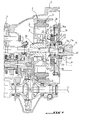
- reference 1 designates a reversible rotating electric machine or alternator-starter, housed in a clutch housing 2 which is fixed between the casing 3 of the gearbox and the casing 4 of the heat engine of a motor vehicle.
- Electric machine 1 is part of a group hybrid powertrain.
- This machine basically includes a stator annular 5 which is fixed relative to the casing clutch 2 and an annular rotor 6 housed in the stator fixes 5 by defining with respect to the latter a gap.
- the rotor 6 is mounted integrally on a support hub 7 which is rotatably mounted relatively to an independent casing 8 via a bearing 9, for example of the ball bearing type.
- the assembly constituted by the stator 5, the rotor 6, the hub 7 and the bearing 9 is housed in the casing independent 8 which is fixed to the clutch housing 2 by fixing screws (not shown) so that the housing 8 is housed in the clutch housing 2 while being spaced from the latter.
- the support hub 7 is arranged concentrically around a primary tree or input tree 10 of the gearbox 3 located downstream of the motor shaft 11 of the thermal motor.
- the primary shaft 10 is mounted at rotation, at its end opposite to the gearbox 3, in a blind bore 11a made at the end of the shaft engine or crankshaft 11 of the heat engine.
- the tree primary 10 can be taken up in the nose of the tree crankshaft 11a by means of bearing 11b.
- the rotor 6 of the electric machine 1 is coupled to the primary shaft 10 via a part coupling 12 comprising a sleeve 13 arranged concentrically between the hub 7 of the rotor 6 and the shaft primary 10 by being linked in rotation to the latter by splines, and a circular plate 14 integral with the sleeve 13 at one end thereof and fixed to the hub 7 for example by screws (not shown).
- the sleeve 13 and the plate 14 are preferably made in one piece.
- a flywheel 16 is fixed to the shaft of crankshaft 11 by fixing screws 17.
- a coupling device is provided in place of the traditional piloted clutch between the crankshaft 11 and the primary shaft 10 of the gearbox.
- This coupling device comprises a wheel free 18 interposed between the crankshaft 11 and the primary shaft 10 so as to occupy either a state free to which the two shafts 10, 11 are not coupled to each other if the speed of rotation of the shaft of crankshaft 11 is less than the rotation speed of the primary shaft 10, a blocked state in which both shafts 10, 11 are coupled to each other if the speed of rotation of the crankshaft 11 is equal to that of the primary shaft 10 and if the force torque of the engine is positive.
- the freewheel 18 which will be described is of the type rollers or cams known per se but it's fine understood that it can be of any other type, such as freewheel with front pawls.
- the freewheel 18 comprises a ring inner 19 linked in rotation to the primary shaft 10 by grooves 20, an outer ring 21 centered relative to the inner ring 20 by two bearings axially distant from each other 22 and rollers or cylindrical rollers 23 regularly interposed between the two inner 19 and outer 21.
- the freewheel 18 can be coupled to the shaft of crankshaft 11 through a stage of filtration of cyclic engine irregularities thermal.
- This filtration stage includes two plates twin annulars 24, 25 concentrically surrounding with radial clearance the outer ring 21 of the freewheel 18 extending perpendicular to the primary shaft 10.
- the 24 larger diameter twin plates is secured by fixing screws 26 to the steering wheel of inertia 16 while being pressed against the face upright 16a of this flywheel and the two annular plates 24, 25 are twinned to each other by rivets 27 extending parallel to the longitudinal axis of the tree primary 10 and evenly spaced from each other so as to keep apart from one another distance determined by the two plates 24, 25.
- the plate 25 is shown in Figure 2 which shows two sets of holes 28 allowing the passage of the rivets 27 and located respectively on two separate circumferences of plate 25, each of the series comprising four 28 regularly spaced holes.
- the plate 24 also has two series of holes identical to those of plate 25 for the passage of rivets 27.
- the filtration stage also includes a plate intermediate annular 29, better visible in FIG. 3, disposed between the two plates 24, 25 substantially parallel to these and which is united in rotation of the outer ring 21 of the freewheel 18 by means of domed grooves 30 in the plate 29 cooperating with domed teeth of the ring exterior 21.
- This spline connection has a clearance sufficient to allow radial movements between the intermediate plate 29 and the outer ring 21 of the wheel free 18 as well as relative share deflections and else from its transverse position to the shaft 10 of the intermediate plate 29 relative to the ring outer 21.
- the grooves are curved in the direction where their generatrices are not parallel lines to the axis of the outer ring 21, but arcs of a circle of large radius.
- Figure 3 shows that the grooves 30 are made in an intermediate annular ring 31 coaxially secured to the circular central opening of the intermediate plate 29, but such grooves can be made directly in plate 29 depending on the material of the latter. Rivets 27 joining the annular plates 24, 25 through holes 32 of plate 29 and a diameter greater than the diameter of the rivets and therefore at diameter of the holes 28 in the plate 25.
- the filtration stage finally comprises at least two elastic members 33, preferably four in number, allowing the coupling of the intermediate plate 29 to the two twin plates 24, 25.
- These elastic members 33 are constituted by helical compression springs integral with the intermediate plate 29 so as to allow the twin plates 24, 25 to apply to the springs 33 a couple of forces headed in the direction elasticity of springs 33, torque which is transmitted to the intermediate plate 29 and the primary shaft 10 when the freewheel 18 is in the locked state coupling the crankshaft 11 to the shaft primary 10.
- the springs 33 are held respectively in diametrically opposed rectangular windows 34 of the intermediate plate 29 overflowing with their turns symmetrically adjacent on either side of the plate 29 so that each spring 33 can also be housed respectively in two rectangular windows 35 of the two plates 24, 25, identical to the window 34 comprising the spring 33 and located on either side of window 34 opposite the latter. More specifically, the rectangular windows 34 will oriented so that their main axes geometrically merged respectively with the axes longitudinal springs 33 are two by two parallel and tangential to a plate circle intermediate 29 and each spring 33 is mounted prestressed in its window 34 by its two turns extremes 33a bearing respectively on the two edges 34a of window 34 extending transversely to the axis longitudinal of the spring 33.
- Each spring 33 is held in the corresponding window 34 by a tongue 36 integral with one of the transverse edges 34a window 34 extending perpendicularly to this one in the plane of the intermediate plate 29 and passing substantially coaxially through the spring 33 until its free end is located at the near the opposite transverse edge 34a of the window 34.
- Window arrangements 35 plates 24 and 25 are identical to those of the windows 34 of plate 29 and each spring 33, overflowing symmetrically from window 34 on either side of the intermediate plate 29 also has its extreme turns 33a resting on the corresponding transverse edges 35a of the two windows 35 of the plates 24, 25 located on each side of window 34 opposite it.
- hybrid powertrain including the choice of engine and engine power ratings reversible rotating electric machine, it is imperative to couple and transmit the engine torque thermal to the primary shaft 10 of the gearbox as soon as a potential contribution is requested from thermal motor.
- the freewheel 18 is in the free state so that the primary shaft 10 is uncoupled from the crankshaft 11 and therefore no torque is transmitted.
- the two shafts 10, 11 are coupled to each other and the entire engine torque is transmitted to the shaft primary.
- the two twin plates 24, 25 exert tangential forces on the springs 33 which transmit these forces to the intermediate plate 29 by their extreme turns 33a resting on the edges corresponding transverse 34a of the windows 34 and, by Consequently, to the outer ring 21 of the freewheel 18.
- the springs 33 filter cyclic irregularities in the engine and ensuring protection of the freewheel.
- the coupling device of the invention can be inserted between any type of motor, except petrol or diesel, regardless of the number of cylinders of it and any type of transmission.
- this coupling device allows use an electric motor capable of driving all conditions the vehicle, the most severe being hill start of the vehicle, up to a speed which corresponds to the minimum regime of operation of the heat engine, corresponding to about 10 km / hour.
- the coupling device also makes it possible to remove the clutch close control as well as the actuator necessary to control it. he allows you to delete or simplify part of the power and control electronics of the transmission.
- This coupling device allows also to simplify the overall control of the chain traction (strategies, electronic architecture, interfaces, software, etc.). Finally, it allows a gain of place in the clutch or converter housing since the freewheel is less bulky than the clutch, so the space gained can be allocated to the reversible rotating electric machine.
- the number of springs, rivets and teeth / splines is given and shown only as indicative and may vary.
Landscapes
- Engineering & Computer Science (AREA)
- Mechanical Engineering (AREA)
- Chemical & Material Sciences (AREA)
- Combustion & Propulsion (AREA)
- Transportation (AREA)
- General Engineering & Computer Science (AREA)
- Hybrid Electric Vehicles (AREA)
Applications Claiming Priority (2)
| Application Number | Priority Date | Filing Date | Title |
|---|---|---|---|
| FR0302228 | 2003-02-24 | ||
| FR0302228A FR2851518B1 (fr) | 2003-02-24 | 2003-02-24 | Dispositif d'accouplement entre l'arbre moteur d'un moteur thermique d'un groupe motopropulseur hybride d'un vehicule automobile et l'arbre primaire de la boite de vitesses de ce vehicule |
Publications (1)
| Publication Number | Publication Date |
|---|---|
| EP1449701A1 true EP1449701A1 (de) | 2004-08-25 |
Family
ID=32732060
Family Applications (1)
| Application Number | Title | Priority Date | Filing Date |
|---|---|---|---|
| EP04290483A Withdrawn EP1449701A1 (de) | 2003-02-24 | 2004-02-23 | Kupplungsvorrichtung zwischen der Motorwelle eines Verbrennungsmotors eines Hybridfahrzeugantriebssystem und der Eingangswelle des Fahrzeugschaltgetriebes |
Country Status (2)
| Country | Link |
|---|---|
| EP (1) | EP1449701A1 (de) |
| FR (1) | FR2851518B1 (de) |
Cited By (2)
| Publication number | Priority date | Publication date | Assignee | Title |
|---|---|---|---|---|
| CN101394119B (zh) * | 2007-09-17 | 2011-06-22 | 襄樊特种电机有限公司 | 一种客车用发电机 |
| GB2572172A (en) * | 2018-03-21 | 2019-09-25 | Ashwoods Electric Motors Ltd | Radial flux electrical machines |
Citations (4)
| Publication number | Priority date | Publication date | Assignee | Title |
|---|---|---|---|---|
| EP0724978A1 (de) * | 1995-02-03 | 1996-08-07 | FICHTEL & SACHS AG | Parallelhybridantrieb für ein Kraftfahrzeug |
| US5931271A (en) * | 1997-09-19 | 1999-08-03 | General Motors Corporation | Hybrid drive with one-way drive connections |
| DE10015912A1 (de) * | 2000-03-30 | 2001-10-31 | Mannesmann Sachs Ag | Kupplung und Antriebsanordnung |
| EP1281557A1 (de) * | 2001-07-31 | 2003-02-05 | Renault s.a.s. | Hybridantrieb mit sperrbarem Planetengetriebe und Freilaufkupplung |
-
2003
- 2003-02-24 FR FR0302228A patent/FR2851518B1/fr not_active Expired - Fee Related
-
2004
- 2004-02-23 EP EP04290483A patent/EP1449701A1/de not_active Withdrawn
Patent Citations (4)
| Publication number | Priority date | Publication date | Assignee | Title |
|---|---|---|---|---|
| EP0724978A1 (de) * | 1995-02-03 | 1996-08-07 | FICHTEL & SACHS AG | Parallelhybridantrieb für ein Kraftfahrzeug |
| US5931271A (en) * | 1997-09-19 | 1999-08-03 | General Motors Corporation | Hybrid drive with one-way drive connections |
| DE10015912A1 (de) * | 2000-03-30 | 2001-10-31 | Mannesmann Sachs Ag | Kupplung und Antriebsanordnung |
| EP1281557A1 (de) * | 2001-07-31 | 2003-02-05 | Renault s.a.s. | Hybridantrieb mit sperrbarem Planetengetriebe und Freilaufkupplung |
Cited By (2)
| Publication number | Priority date | Publication date | Assignee | Title |
|---|---|---|---|---|
| CN101394119B (zh) * | 2007-09-17 | 2011-06-22 | 襄樊特种电机有限公司 | 一种客车用发电机 |
| GB2572172A (en) * | 2018-03-21 | 2019-09-25 | Ashwoods Electric Motors Ltd | Radial flux electrical machines |
Also Published As
| Publication number | Publication date |
|---|---|
| FR2851518A1 (fr) | 2004-08-27 |
| FR2851518B1 (fr) | 2006-02-10 |
Similar Documents
| Publication | Publication Date | Title |
|---|---|---|
| EP1232891B1 (de) | Bewegungsübertragungsvorrichtung für Hybridfahrzeuge | |
| EP1567766B1 (de) | Antriebssystem für verbrennungsmotor und starter-generator | |
| FR2959547A1 (fr) | Poulie de decouplage. | |
| EP0148664A1 (de) | Durch elektrischen Motor unterstützte Kraftfahrzeuglenkung | |
| EP0237373A1 (de) | Fahrzeug-Schwungrad | |
| EP0172100A1 (de) | Drehschwingungsdämpfer mit grossem Winkelbereich, insbesondere Kupplungsscheibe, z.B. für Brennkraftmaschinen | |
| EP4247657A1 (de) | Elektrische antriebsvorrichtung für eine fahrzeugachse | |
| EP1232890B1 (de) | Schaltgetriebe für ein Hybridfahrzeug | |
| EP0824641A1 (de) | Stufenloses getriebe mit hohem wirkungsgrad für brennkraftmaschinen, besonders von fahrzeugen | |
| EP1279828B1 (de) | Nachgiebige Kupplung zur Verbindung des Rotors einer elektischen Maschine mit der Kurbelwelle des Verbrennungsmotors eines Kraftfahrzeugs | |
| FR2550508A1 (fr) | Dispositif moteur pour vehicule leger | |
| FR2660038A1 (fr) | Double volant amortisseur, notamment pour vehicule automobile. | |
| FR2728040A1 (fr) | Amortisseur de torsion a mecanisme de transmission intermediaire, notamment pour un embrayage | |
| EP0631070B1 (de) | Kupplungslose Getriebevorrichtung für Kraftfahrzeuge | |
| FR2609132A1 (fr) | Volant amortisseur pour transmission, notamment pour vehicule automobile | |
| FR2851518A1 (fr) | Dispositif d'accouplement entre l'arbre moteur d'un moteur thermique d'un groupe motopropulseur hybride d'un vehicule automobile et l'arbre primaire de la boite de vitesses de ce vehicule | |
| EP4380810B1 (de) | Antriebsstrang für ein hybrid-antriebs- oder zugkraftfahrzeug mit einem mechanismus zum blockieren des verbrennungsmotors | |
| FR3071576B1 (fr) | Dispositif de transmission de vitesse avec marche arriere pour le deplacement d'un vehicule automobile, notamment d'un vehicule motorise a au moins deux-roues | |
| FR2875883A1 (fr) | Demarreur equipe d'un mecanisme de boite de reduction de vitesse a deux etapes | |
| FR2859006A1 (fr) | Dispositif de changement de vitesse, ensemble et vehicule automobile correpondants | |
| FR2498392A1 (fr) | Perfectionnements aux demarreurs electriques pour moteurs a combustion interne comportant un reducteur insere entre son moteur electrique et son lanceur | |
| FR3071889B1 (fr) | Systeme d'embrayage comportant un plateau de reaction supporte par un organe d'entree | |
| FR2714950A1 (fr) | Réducteur-variateur. | |
| FR2798328A1 (fr) | Systeme de transmission de mouvement pour vehicule a propulsion hybride | |
| FR2864592A1 (fr) | Poulie a embrayage a roue libre pour l'entrainement en rotation d'un alternateur de vehicule automobile |
Legal Events
| Date | Code | Title | Description |
|---|---|---|---|
| PUAI | Public reference made under article 153(3) epc to a published international application that has entered the european phase |
Free format text: ORIGINAL CODE: 0009012 |
|
| AK | Designated contracting states |
Kind code of ref document: A1 Designated state(s): AT BE BG CH CY CZ DE DK EE ES FI FR GB GR HU IE IT LI LU MC NL PT RO SE SI SK TR |
|
| AX | Request for extension of the european patent |
Extension state: AL HR LT LV MK |
|
| 17P | Request for examination filed |
Effective date: 20041230 |
|
| AKX | Designation fees paid |
Designated state(s): AT BE BG CH CY CZ DE DK EE ES FI FR GB GR HU IE IT LI LU MC NL PT RO SE SI SK TR |
|
| STAA | Information on the status of an ep patent application or granted ep patent |
Free format text: STATUS: THE APPLICATION HAS BEEN WITHDRAWN |
|
| 18W | Application withdrawn |
Effective date: 20090504 |