EP1449713B1 - Appui-tête avec support de tête coulissant et coussins latéraux de confort - Google Patents
Appui-tête avec support de tête coulissant et coussins latéraux de confort Download PDFInfo
- Publication number
- EP1449713B1 EP1449713B1 EP04090055A EP04090055A EP1449713B1 EP 1449713 B1 EP1449713 B1 EP 1449713B1 EP 04090055 A EP04090055 A EP 04090055A EP 04090055 A EP04090055 A EP 04090055A EP 1449713 B1 EP1449713 B1 EP 1449713B1
- Authority
- EP
- European Patent Office
- Prior art keywords
- headrest
- supporting part
- comfort
- comport
- wing
- Prior art date
- Legal status (The legal status is an assumption and is not a legal conclusion. Google has not performed a legal analysis and makes no representation as to the accuracy of the status listed.)
- Expired - Lifetime
Links
- 125000006850 spacer group Chemical group 0.000 claims description 5
- ATJFFYVFTNAWJD-UHFFFAOYSA-N Tin Chemical compound [Sn] ATJFFYVFTNAWJD-UHFFFAOYSA-N 0.000 claims 2
- 239000004576 sand Substances 0.000 claims 1
- 238000006073 displacement reaction Methods 0.000 description 19
- 238000000926 separation method Methods 0.000 description 11
- 230000008878 coupling Effects 0.000 description 3
- 238000010168 coupling process Methods 0.000 description 3
- 238000005859 coupling reaction Methods 0.000 description 3
- 101100465000 Mus musculus Prag1 gene Proteins 0.000 description 1
- 230000001154 acute effect Effects 0.000 description 1
- 230000036461 convulsion Effects 0.000 description 1
- 230000003287 optical effect Effects 0.000 description 1
- 230000006641 stabilisation Effects 0.000 description 1
- 238000011105 stabilization Methods 0.000 description 1
Images



Classifications
-
- B—PERFORMING OPERATIONS; TRANSPORTING
- B60—VEHICLES IN GENERAL
- B60N—SEATS SPECIALLY ADAPTED FOR VEHICLES; VEHICLE PASSENGER ACCOMMODATION NOT OTHERWISE PROVIDED FOR
- B60N2/00—Seats specially adapted for vehicles; Arrangement or mounting of seats in vehicles
- B60N2/80—Head-rests
- B60N2/806—Head-rests movable or adjustable
- B60N2/865—Head-rests movable or adjustable providing a fore-and-aft movement with respect to the occupant's head
-
- B—PERFORMING OPERATIONS; TRANSPORTING
- B60—VEHICLES IN GENERAL
- B60N—SEATS SPECIALLY ADAPTED FOR VEHICLES; VEHICLE PASSENGER ACCOMMODATION NOT OTHERWISE PROVIDED FOR
- B60N2/00—Seats specially adapted for vehicles; Arrangement or mounting of seats in vehicles
- B60N2/80—Head-rests
- B60N2/806—Head-rests movable or adjustable
- B60N2/809—Head-rests movable or adjustable vertically slidable
-
- B—PERFORMING OPERATIONS; TRANSPORTING
- B60—VEHICLES IN GENERAL
- B60N—SEATS SPECIALLY ADAPTED FOR VEHICLES; VEHICLE PASSENGER ACCOMMODATION NOT OTHERWISE PROVIDED FOR
- B60N2/00—Seats specially adapted for vehicles; Arrangement or mounting of seats in vehicles
- B60N2/80—Head-rests
- B60N2/806—Head-rests movable or adjustable
- B60N2/809—Head-rests movable or adjustable vertically slidable
- B60N2/812—Head-rests movable or adjustable vertically slidable characterised by their locking devices
- B60N2/821—Head-rests movable or adjustable vertically slidable characterised by their locking devices with continuous positioning
-
- B—PERFORMING OPERATIONS; TRANSPORTING
- B60—VEHICLES IN GENERAL
- B60N—SEATS SPECIALLY ADAPTED FOR VEHICLES; VEHICLE PASSENGER ACCOMMODATION NOT OTHERWISE PROVIDED FOR
- B60N2/00—Seats specially adapted for vehicles; Arrangement or mounting of seats in vehicles
- B60N2/80—Head-rests
- B60N2/806—Head-rests movable or adjustable
- B60N2/868—Head-rests movable or adjustable providing a lateral movement parallel to the occupant's shoulder line
-
- B—PERFORMING OPERATIONS; TRANSPORTING
- B60—VEHICLES IN GENERAL
- B60N—SEATS SPECIALLY ADAPTED FOR VEHICLES; VEHICLE PASSENGER ACCOMMODATION NOT OTHERWISE PROVIDED FOR
- B60N2/00—Seats specially adapted for vehicles; Arrangement or mounting of seats in vehicles
- B60N2/80—Head-rests
- B60N2/885—Head-rests provided with side-rests
Definitions
- the present invention relates to a headrest for a vehicle seat with the features mentioned in the preamble of claim 1.
- the patent DE 196 02 909 C2 describes a headrest for vehicle seats, on which at its front a contact surface for the head of the seat occupant is formed, which is adjustable in at least one lying laterally from the vertical center plane of the headrest portion in different positions. As a result, different sized acute angle with the vertical center plane of the backrest are formed.
- the publication DE 202 05 348 U1 teaches a headrest for seats, which consists of two independently pivotable and height-adjustable parts. The back of these parts offer the head of a seat occupant swung out a contact surface and thus a lateral support, the front only serves as a contact surface for the head of the seat occupant intientschwenktem state.
- the publication WO 95/09742 A1 describes a headrest nack the preamble of claim 1, which has a good adjustability.
- a trained as a headrest support member structure is reversibly displaceable horizontally and vertically relative to a frame of a seat part via an adjusting mechanism. The structure is arranged obliquely relative to the frame so that it can be displaced not only vertically upwards and downwards or horizontally to the left and right, but also forward or backward by its oblique position during the vertical movement of the structure.
- the invention has the object, in a vehicle seat of the type mentioned in the comfort and safety of the seated vehicle occupant to continue to improve.
- an adjusting mechanism has at least one vertical guide means and at least one horizontal guide means which are interconnected via a connecting means, whereby a Kopf spanauflageteil on the adjusting mechanism relative to a headrest base both in a first horizontal spatial direction in the x-direction and in a second vertical spatial direction in the y-direction and the at least one lateral first and second headrest comfort wings relative to the headrest base body by means of a first and second adjustment in addition in a third spatial direction in the z-direction reversibly displaced is.
- the headrest support part is thus reversibly displaceable in the x-direction and y-direction relative to the headrest main body, the first and second headrest comfort wings also being reversibly displaceable in the z-direction, whereby comfortable lateral contact surfaces form for the head of the seat user.
- a preferred embodiment is to shift the lateral first headrest comfort wing or second headrest comfort wing in the z-direction so that in an upright sitting position of the seat occupant, a central, central support area on the at least one head rest support part for the back of the head or neck of the seat occupant formed.
- an adjusting mechanism is arranged in various embodiments between the headrest base body and the at least one headrest support part or essentially in the headrest base body or substantially in the at least one headrest support part.
- the adjustment mechanism of the headrest has the at least one vertical guide means and the at least one horizontal guide means for the head restraint part.
- the at least one vertical guide means comprises the connection means for connection to the at least one horizontal guide means.
- the horizontal guide means further comprises a first adjusting element and a second adjusting element, which also comprises a first and a second joint or the like, which connects the at least one horizontal guide means with the first adjusting element or the second adjusting element.
- the first and second adjusting elements are in contact with the first and second headrest comfort wings, respectively, whereby an adjustment of the first or second headrest comfort wing in the z-direction can be carried out.
- the displacement of the at least one headrest support part in the x-direction and / or y-direction and the displacement of the at least one first headrest comfort wing and / or the second headrest comfort wing in the z-direction manually and / or via actuators feasible.
- These actuators are according to the invention electrically, pneumatically and hydraulically driven or in any combination.
- a particular adjustment of the actuating forces, which are selectable for the displacement of the at least one headrest support part and / or the first and second headrest comfort wing in the Ausstellposition the spatial directions (x, y, z), allows the initial position on the one hand by manual operation or by a nakedness Kopfbeetzschung the head of a vehicle occupant can be restored.
- the setting of the actuating forces for displacement of the at least one headrest support part and / or the first and second headrest comfort wing in the Ausstelipositiow the spatial directions selectable according to the viewpoints that in a vehicle crash sensor controlled via the actuators or the like, the starting position can be restored.
- a rearward displacement of the at least one headrest support member may be carried out with his, that both by the mere application of the head as well as sensor-controlled a jerk-bearing in the starting position can be performed.
- FIG. 1 shows first in a perspective view a headrest 10 in a starting position.
- the headrest 10 has a headrest main body 18 and a headrest rest 12. Between the headrest base body 18 and the head restraint support part 12 there is formed an in-plane continuous separation joint 20. Between the headrest base body 18 and the headrest support part 12, an adjusting mechanism 22 is further arranged.
- FIG. 1 shows a known headrest bracket 24 of the headrest 10th
- FIG. 2 shows the headrest 10 with the head support brackets 24 with the same designated elements, the headrest base 18, the headrest support member 12, the separating gap 20 arranged therebetween in a deployed position.
- the headrest support member 12 is displaced in a z-space direction in this perspective view. This displacement relates to a first headrest comfort wing 14 and a second headrest comfort wing 16 Based on the spatial directions (x, y, z), the further features in the following exemplary embodiments are described in more detail below.
- the same components are always assigned the same reference numerals, wherein in the FIGS. 3 to 10 already described components and functions will not be explained again in each case.
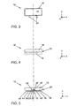
- FIG. 3 shows a schematic front view of the headrest 10, which represents the headrest support member 12 in the starting position in front of the headrest base body 18 together with the headrest brackets 24.
- the headrest support member 12 is not displaced in the x-direction x in the y-direction y nor in the z-direction z.
- FIG. 4 First, a simplified schematic plan view of the headrest 10th
- FIG. 4 shows the headrest 10 in plan view and illustrates the separation gap 20 between the headrest body 18 and headrest support member 12th
- FIG. 5 added FIG. 4 in that the headrest 10, consisting of the headrest base body 18 and the headrest support member 12, the adjusting mechanism 22 in a further plan view shows.
- the adjusting mechanism 22 is in FIG. 5 arranged in the separation joint 20.
- the adjusting mechanism 22 has a vertical guide means 26 and a horizontal guide means 28. These guide means 26, 28 can be designed both as rail and locking systems or the like.
- the vertical guide means 26 and the horizontal guide means 28 are connected to each other via a connecting means 30.
- the horizontal guide means 28 in the y-direction in the vertical guide means 26 is displaced. This displacement in the y-direction y, which is possible into the plane of the page or out of the plane of the page, is in FIG. 4 can not be displayed.
- the horizontal guide means 28 comprises a first joint 38 and a second joint 40, to each of which a first adjustment element 34 and a second adjustment element 36 connect along the x-axis.
- the horizontal guide means 28 further comprises a fastening means 32 which is connected to the headrest support part 12.
- the adjusting elements 34, 36 allow in the in FIG. 5 shown arrangement an additional stabilization of the head restraint part 12th
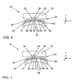
- FIG. 6 shows the displacement of the headrest support member 12 from the in FIG. 5 shown starting position in an exemplary desired deployment position.
- the headrest support part 12 is made deformable or flexible.
- FIG. 6 shows in the schematic plan view of the arrangement of the adjusting mechanism 22 in the parting line 20 in the raised position.
- the first adjusting element 34 and the second adjusting element 36 are displaced via the first joint 38 and the second joint 40 in the z-direction z, respectively.
- the contact between the first adjusting element 34 and the second adjusting element 36 is produced by a respective spacer 42 or the like.
- the dashed lines show the The central position along an imaginary center line of the horizontal guide means 28 is formed on the headrest support member 12, a central support portion 46 from.
- This support area 46 allows the seat occupant to lean against the headrest 10 in an average normal position.
- the first and second headrest comfort wings 14 and 16 formed by adjustment at the starting position into the deployed position now also allow a comfortable leaning in the lateral area of the head of the seat occupant.
- FIG. 7 shows the headrest 10 in a schematic plan view in another display position.
- the headrest support member 12 is displaced in both the x-direction x and the z-direction z. Due to the two-dimensional representation, a displacement in the y-direction can not be represented. It is visible that the support area 46 is displaced out of an imaginary center line by displacement in the x-direction x for the back of the head of the seat occupant.
- FIG. 8 shows the schematic plan view of the headrest 10 with the arranged in the headrest body 18 adjustment mechanism 22 already in another exemplary display position. This embodiment is based on the idea of forming the separation gap 20 as small as possible for reasons of optical design.
- FIG. 8 shows in a further preferred embodiment, that a connection between the adjusting elements 34, 36 to the first and second headrest comfort wings 14, 16 via spacer arm 44 is executable.
- the distance control arms 44 in FIG. 8 not shown
- the dashed each The illustrated lines again show the headrest support part 12 and the adjusting elements 34, 36 in their starting position.
- FIG. 9 shows a headrest 10 in principle similar executed according to FIG. 8 as a schematic plan view, but in a different Ausstellposition.
- This deployment position is similar FIG. 7 a displaced in the x direction x headrest support member 12 with simultaneous displacement of the first and second headrest comfort wing 14, 16 in the z-direction.
- a displacement of the entire headrest support member 12 in the opposite x-direction x is possible.
- FIG. 10 finally shows such a displacement of the headrest support member 12 in the opposite x-direction x with a further possibility of variable Ausstellpositionen.
- the first headrest comfort wing 14 is displayed in a deployed position in the z-direction z.
- the adjustment mechanism 22 can also be arranged essentially in the head restraint support part 12.
- a corresponding locking means similar to the described connecting means 30 between the head restraint support part 12 and the headrest main body 18 then necessarily represents the connection between the components.
- the actuating forces for displacement of the at least one head restraint part 12 and / or the first and second headrest comfort wing 14, 16 are selected in the Ausstellposition such that by manual operation or by a mere head of a head Vehicle occupants the starting position is reversibly restored.
- the actuating forces for displacing the at least one head restraint support part 12 and / or the first and second headrest comfort vanes 14, 16 into the deployed position and back are selected in such a way that, in the event of an event Vehicle crash sensor-controlled, a return adjustment to the starting position of the actuators in a very short time is feasible.
- a three-dimensional adjustability of the head restraint support part 12 on a continuous separation gap 20 lying in one plane is thus possible.
- the additional comfort features also make it possible to further improve occupant protection in event of an accident.
Landscapes
- Engineering & Computer Science (AREA)
- Aviation & Aerospace Engineering (AREA)
- Transportation (AREA)
- Mechanical Engineering (AREA)
- Seats For Vehicles (AREA)
- Chair Legs, Seat Parts, And Backrests (AREA)
Claims (11)
- Appuie-tête (10) pour un siège, notamment pour un siège de véhicule automobile, avec au moines un support d'appuie-tête (12) mobile comprenait au moines un premier coussin latéral de confort d'appuie-tête (14) et un deuxième coussin latéral de confort d'appuie-tête (16) pouvant être amenées d'une positron de départ s'étendant pour l'essentiel parallèlement à un corps de base d'appuie-tête (18) dans au moins une position de réglage, l'au moins un support d/appuie-tête (12) et le corps de base d'appuie-tête (18) étant reliés entré eux par le biais d'au moins un mécanisé de réglage (22) et un joint de séparation (20) traversait reposant dans un plan pétant réalise entré eux, caractérisé sen ce que le mécanisme de réglage (22) comporté au moins un moyen de guidage vertical (26) et au moins un moyen de guidage horizontal (28) reliés enture eux par le biais d'un moyen de liaison (30), faisant que le support d'appuie-tête (12) peut être déplacé de façon réversible par le mécanisme de réglage (22) par rapport au corps de base d'appuie-tête (18) tant dans une première direction horizontales dans l'espace dans la direction x (x) que dans une deuxième dilection verticale dans l'espace dans la direction y (y) et que l'au moins un premier et un deuxième coussin latéral de consort d'appuie-tête (14, 16) peuvent en outré être déplacés de façon réversible par rapport au corps de base d'appuie-tête (18) par le biais d'un premier et d'un deuxième élément de réglage (34, 36) dans unie troisième dilection dans l'espace dans la direction z (z).
- Appuie-tête selon la revendication 1, caractérisé en ce qu'une zone d'appui (46) centrale pouvant être déplacée tant dans la première direction horizontale dans l'espace dans la direction x (x) que dans la deuxième direction verticale dans l'espace dans la direction y (y) est réalisée entre l'au moines un premier et un deuxième coussin latéral de confort d'appuie-tête (14, 16) de l'au moines un support d'appuie-tête (12).
- Appuie-tête selon la revendication 1, caractérisé sen ce que l'au moines un mécanisme de réglage (22) est dispose pour l'essentiel entre le corpus de base d'appuie-tête (18) et l'au moins un support d'appuie-tête (12) ou dans lue corpus de base d'appuie-tête (18) ou dans le support d'appuie-tête (12).
- Appuie-tête selon la revendication 1, caractérisé sen ce que l'au moines un premier est deuxième élément de réglage (34, 36) est dispose au niveau du moyen de guidage horizontal (28).
- Appuie-tête selon la revendication 4, caractérisé sen ce que l'au moines un moyen de guidage horizontal (28) comprend une première articulation (38) et unie deuxième articulation (40) par le bilais desquelles le premier élément de réglage (34) et le deuxième élément de réglage (36) sont reliés à l'au moines un moyen de guidage horizontal (28).
- Appuie-tête selon la revendication 1, caractérisé en ce que le premier coussin latéral de consort d'appuie-tête (14) et/ou le deuxième coussin latéral de confort d'appuie-tête (16) comprennent au moins une entretoise (42) et/ou au moins un bras d'écartement (44) en contact avec le premier et/ou le deuxième élément de réglage (34, 36) respectif.
- Appuie-tête selon la revendication 1, caractérisé en ce que le déplacement de l'au moins un support d'appuie-tête (12) dans la dilection x (x) et/ou dans la dilection (y) et le déplacement de l'au moines un premier et/ou un deuxième coussin de confort d"appuie-tête (14, 16) dans la direction z (z) peut être réalisé manuellement et/ou par le biais d'entraînements de réglage.
- Appuie-tête selon la revendication 7, caractérisé en ce que les entraînements de réglage peuvent être entraînées de façon électrique, pneumatique ainsi qu'hydraulique ou selon une combinaison quelconque de ces modes de fonctionnement.
- Appuie-tête selon la revendication 1, caractérisé en ce que les forces de réglage permettant de déplacer l'au moins un support d"appuie-tête (12) et/ou le premier et le deuxième coussin de confort d'appuie-tête (14, 16) dans la position de réglage sont choisies de façon à ce que la position de départ puisse être retrouvée de façon réversible par lue biais d'un actionnement manuel ou d'un simple coup de tête appliqué contre l'au moins un support d'appuie-tête (12) et/ou contre le premier et/ou le deuxième coussin latéral de confort d'appuie-tête (14, 16).
- Appuie-tête selon la revendication 1, caractérisé en ce que les forces de réglage servant à déplacer l'au moins un support d'appuie-tête (12) et/ou le premier et le deuxième coussin de confort d'appuie-tête (14, 16) dans la position de réglage sont choisi de façon à ce que la position de départ puisse être retrouvée de façon réversible par le biais d'entraînements de réglage commandées par capteurs sen cas de choc du véhicule.
- Appuie-tête selon la revendication 9 et 10, caractérisé sen ce que le déplacement vers l'arrière du support d'appuie-tête (12) ou des coussins latéraux de confort d'appuie-tête (14, 16) de la position de réglage dans la position de départ peut être réalise en combinant actionnement manuel est actionnement commande par capteur.
Applications Claiming Priority (2)
| Application Number | Priority Date | Filing Date | Title |
|---|---|---|---|
| DE10308569 | 2003-02-24 | ||
| DE10308569 | 2003-02-24 |
Publications (3)
| Publication Number | Publication Date |
|---|---|
| EP1449713A2 EP1449713A2 (fr) | 2004-08-25 |
| EP1449713A3 EP1449713A3 (fr) | 2005-12-28 |
| EP1449713B1 true EP1449713B1 (fr) | 2012-01-18 |
Family
ID=32731141
Family Applications (1)
| Application Number | Title | Priority Date | Filing Date |
|---|---|---|---|
| EP04090055A Expired - Lifetime EP1449713B1 (fr) | 2003-02-24 | 2004-02-17 | Appui-tête avec support de tête coulissant et coussins latéraux de confort |
Country Status (3)
| Country | Link |
|---|---|
| EP (1) | EP1449713B1 (fr) |
| AT (1) | ATE541742T1 (fr) |
| DE (1) | DE10361958A1 (fr) |
Cited By (2)
| Publication number | Priority date | Publication date | Assignee | Title |
|---|---|---|---|---|
| US10252657B2 (en) | 2014-12-12 | 2019-04-09 | Bombardier Inc. | Headrest with adjustable side elements |
| US10773626B2 (en) | 2015-03-31 | 2020-09-15 | Safran Seats Usa Llc | Adjustable headrest enabling sideward leaning and seclusion |
Families Citing this family (10)
| Publication number | Priority date | Publication date | Assignee | Title |
|---|---|---|---|---|
| FR2897312B1 (fr) * | 2006-02-13 | 2008-04-18 | Peugeot Citroen Automobiles Sa | Appui-tete reglable pour siege de vehicule automobile ou analogue |
| CN102795133A (zh) * | 2012-07-21 | 2012-11-28 | 长春富维-江森自控汽车饰件系统有限公司 | 用于前后与侧翼角度调节的汽车座椅头枕调节机构 |
| CN102795135A (zh) * | 2012-07-21 | 2012-11-28 | 长春富维-江森自控汽车饰件系统有限公司 | 汽车座椅头枕的六向电动调节机构 |
| FR3008043B1 (fr) * | 2013-07-02 | 2015-07-17 | Peugeot Citroen Automobiles Sa | Dispositif amovible d'appui d'une tete et/ou d'un cou, pour un appui-tete d'un dossier de siege |
| DE102014110051B4 (de) * | 2014-07-17 | 2017-11-23 | Faurecia Autositze Gmbh | Stützstruktur, insbesondere Kopfstützenstruktur für einen Fahrzeugsitz |
| US20200282888A1 (en) * | 2017-09-12 | 2020-09-10 | Adient Engineering and IP GmbH | Head restraint for a seat back of a vehicle seat and vehicle seat |
| DE102018109419A1 (de) * | 2018-04-19 | 2019-10-24 | Faurecia Autositze Gmbh | Verstellbare Kopfstütze für einen Kraftfahrzeugsitz |
| DE102019200991B4 (de) | 2019-01-28 | 2023-12-14 | Audi Ag | In Querrichtung bewegliche Kopfstütze mit einseitigem Verbindungsabschnitt, Sitz mit einer Kopfstütze und Kraftfahrzeug mit Sitz |
| DE102019117990A1 (de) * | 2019-07-03 | 2021-01-07 | Bayerische Motoren Werke Aktiengesellschaft | Sitz mit Kopfstütze für ein Fortbewegungsmittel und Fortbewegungsmittel |
| DE102020123924B4 (de) | 2020-09-15 | 2024-07-25 | Audi Aktiengesellschaft | Kopfstütze |
Family Cites Families (5)
| Publication number | Priority date | Publication date | Assignee | Title |
|---|---|---|---|---|
| GB9320322D0 (en) * | 1993-10-01 | 1993-11-17 | Aircraft Furnishing Ltd | Coupling apparatus and seat structure |
| DE19602909C2 (de) * | 1996-01-27 | 2001-05-31 | Recaro Aircraft Seating Gmbh | Kopfstütze für Fahrzeugsitze |
| US5586810A (en) * | 1996-02-12 | 1996-12-24 | Liu; Yang-Ting | Adjustable headrest |
| DE10066239B4 (de) * | 2000-02-05 | 2006-07-27 | Bayerische Motoren Werke Ag | Kopfstütze an einem Fahrzeugsitz |
| DE20205348U1 (de) * | 2002-04-06 | 2002-08-29 | TriCon Design AG, 72138 Kirchentellinsfurt | Bifunktionale Kopfstütze für Sitze im öffentlichen Verkehr |
-
2003
- 2003-12-23 DE DE10361958A patent/DE10361958A1/de not_active Ceased
-
2004
- 2004-02-17 AT AT04090055T patent/ATE541742T1/de active
- 2004-02-17 EP EP04090055A patent/EP1449713B1/fr not_active Expired - Lifetime
Cited By (2)
| Publication number | Priority date | Publication date | Assignee | Title |
|---|---|---|---|---|
| US10252657B2 (en) | 2014-12-12 | 2019-04-09 | Bombardier Inc. | Headrest with adjustable side elements |
| US10773626B2 (en) | 2015-03-31 | 2020-09-15 | Safran Seats Usa Llc | Adjustable headrest enabling sideward leaning and seclusion |
Also Published As
| Publication number | Publication date |
|---|---|
| DE10361958A1 (de) | 2004-10-14 |
| EP1449713A3 (fr) | 2005-12-28 |
| EP1449713A2 (fr) | 2004-08-25 |
| ATE541742T1 (de) | 2012-02-15 |
Similar Documents
| Publication | Publication Date | Title |
|---|---|---|
| DE102009021267B4 (de) | Kopfstütze mit Kopfstützen-Komfortflügeln | |
| DE10045474C1 (de) | Fahrzeugsitz mit Packagestellung | |
| DE69304145T2 (de) | Sitz und seine Verwendung in einem Fahrzeug | |
| DE102008004232B3 (de) | Sitzanordnung mit zwei Fahrzeugsitzen in einer Sitzreihe | |
| DE102004057471B4 (de) | Fahrzeugsitz, insbesondere Kraftfahrzeugsitz | |
| DE69616679T2 (de) | In eine Liege veränderbarer Sitz für Flugzeuge | |
| DE102006041915A1 (de) | Fahrzeugsitz, insbesondere Kraftfahrzeugsitz | |
| DE102014200996A1 (de) | Gelenk-Kopfstützeinheit | |
| EP1492703A1 (fr) | Siege, notamment siege pour passager de vol | |
| DE69305716T2 (de) | Kinderrückhaltesitz mit einer Schaum- und einer biegsamen Schicht | |
| EP1449713B1 (fr) | Appui-tête avec support de tête coulissant et coussins latéraux de confort | |
| DE102015116463A1 (de) | Manuelle stütze für obere sitzlehne | |
| DE2911027A1 (de) | Sitz, insbesondere fuer oeffentliche transportfahrzeuge | |
| DE102022120164A1 (de) | Unterschenkelstützvorrichtung für einen fahrzeugsitz sowie fahrzeugsitz | |
| EP1932713A1 (fr) | Siège central pour une banquette arrière de véhicule automobile | |
| DE102005032382B4 (de) | Fahrzeugsitz, insbesondere Kraftfahrzeugsitz | |
| EP0943483A2 (fr) | Agencement d'au moins deux sièges adjacents | |
| DE102018108374A1 (de) | Zusammenklappbarer hebemechanismus zur h-punkt-hebung | |
| DE4432874B4 (de) | Sitz für Eisenbahnwagen oder Straßenbahnwagen | |
| DE102019125035B4 (de) | Fahrzeugsitz mit verstellbarer Armlehne | |
| DE102018108488B4 (de) | Kraftfahrzeug mit einer Pedalkonsole und einem Sitz | |
| DE10311870B4 (de) | Mehrfachsitz für Kraftfahrzeuge, insbesondere Doppelsitzbank | |
| DE102004027900B4 (de) | Fahrzeugsitz | |
| WO2007082686A2 (fr) | Siège de véhicule à siège pour enfant intégré | |
| DE10034441A1 (de) | Fahrzeugsitz |
Legal Events
| Date | Code | Title | Description |
|---|---|---|---|
| PUAI | Public reference made under article 153(3) epc to a published international application that has entered the european phase |
Free format text: ORIGINAL CODE: 0009012 |
|
| AK | Designated contracting states |
Kind code of ref document: A2 Designated state(s): AT BE BG CH CY CZ DE DK EE ES FI FR GB GR HU IE IT LI LU MC NL PT RO SE SI SK TR |
|
| AX | Request for extension of the european patent |
Extension state: AL LT LV MK |
|
| PUAL | Search report despatched |
Free format text: ORIGINAL CODE: 0009013 |
|
| AK | Designated contracting states |
Kind code of ref document: A3 Designated state(s): AT BE BG CH CY CZ DE DK EE ES FI FR GB GR HU IE IT LI LU MC NL PT RO SE SI SK TR |
|
| AX | Request for extension of the european patent |
Extension state: AL LT LV MK |
|
| RIC1 | Information provided on ipc code assigned before grant |
Ipc: 7B 60N 2/48 A Ipc: 7A 47C 7/38 B |
|
| 17P | Request for examination filed |
Effective date: 20060628 |
|
| AKX | Designation fees paid |
Designated state(s): AT BE BG CH CY CZ DE DK EE ES FI FR GB GR HU IE IT LI LU MC NL PT RO SE SI SK TR |
|
| 17Q | First examination report despatched |
Effective date: 20071109 |
|
| GRAP | Despatch of communication of intention to grant a patent |
Free format text: ORIGINAL CODE: EPIDOSNIGR1 |
|
| GRAS | Grant fee paid |
Free format text: ORIGINAL CODE: EPIDOSNIGR3 |
|
| GRAA | (expected) grant |
Free format text: ORIGINAL CODE: 0009210 |
|
| AK | Designated contracting states |
Kind code of ref document: B1 Designated state(s): AT BE BG CH CY CZ DE DK EE ES FI FR GB GR HU IE IT LI LU MC NL PT RO SE SI SK TR |
|
| REG | Reference to a national code |
Ref country code: GB Ref legal event code: FG4D Free format text: NOT ENGLISH |
|
| REG | Reference to a national code |
Ref country code: CH Ref legal event code: EP |
|
| REG | Reference to a national code |
Ref country code: AT Ref legal event code: REF Ref document number: 541742 Country of ref document: AT Kind code of ref document: T Effective date: 20120215 Ref country code: IE Ref legal event code: FG4D Free format text: LANGUAGE OF EP DOCUMENT: GERMAN |
|
| REG | Reference to a national code |
Ref country code: DE Ref legal event code: R096 Ref document number: 502004013241 Country of ref document: DE Effective date: 20120315 |
|
| REG | Reference to a national code |
Ref country code: NL Ref legal event code: VDEP Effective date: 20120118 |
|
| RAP2 | Party data changed (patent owner data changed or rights of a patent transferred) |
Owner name: VOLKSWAGEN AKTIENGESELLSCHAFT |
|
| PG25 | Lapsed in a contracting state [announced via postgrant information from national office to epo] |
Ref country code: NL Free format text: LAPSE BECAUSE OF FAILURE TO SUBMIT A TRANSLATION OF THE DESCRIPTION OR TO PAY THE FEE WITHIN THE PRESCRIBED TIME-LIMIT Effective date: 20120118 Ref country code: BG Free format text: LAPSE BECAUSE OF FAILURE TO SUBMIT A TRANSLATION OF THE DESCRIPTION OR TO PAY THE FEE WITHIN THE PRESCRIBED TIME-LIMIT Effective date: 20120418 |
|
| REG | Reference to a national code |
Ref country code: IE Ref legal event code: FD4D |
|
| BERE | Be: lapsed |
Owner name: VOLKSWAGEN A.G. Effective date: 20120228 |
|
| PG25 | Lapsed in a contracting state [announced via postgrant information from national office to epo] |
Ref country code: GR Free format text: LAPSE BECAUSE OF FAILURE TO SUBMIT A TRANSLATION OF THE DESCRIPTION OR TO PAY THE FEE WITHIN THE PRESCRIBED TIME-LIMIT Effective date: 20120419 Ref country code: PT Free format text: LAPSE BECAUSE OF FAILURE TO SUBMIT A TRANSLATION OF THE DESCRIPTION OR TO PAY THE FEE WITHIN THE PRESCRIBED TIME-LIMIT Effective date: 20120518 Ref country code: FI Free format text: LAPSE BECAUSE OF FAILURE TO SUBMIT A TRANSLATION OF THE DESCRIPTION OR TO PAY THE FEE WITHIN THE PRESCRIBED TIME-LIMIT Effective date: 20120118 |
|
| PG25 | Lapsed in a contracting state [announced via postgrant information from national office to epo] |
Ref country code: MC Free format text: LAPSE BECAUSE OF NON-PAYMENT OF DUE FEES Effective date: 20120229 Ref country code: CY Free format text: LAPSE BECAUSE OF FAILURE TO SUBMIT A TRANSLATION OF THE DESCRIPTION OR TO PAY THE FEE WITHIN THE PRESCRIBED TIME-LIMIT Effective date: 20120118 |
|
| REG | Reference to a national code |
Ref country code: CH Ref legal event code: PL |
|
| PG25 | Lapsed in a contracting state [announced via postgrant information from national office to epo] |
Ref country code: SI Free format text: LAPSE BECAUSE OF FAILURE TO SUBMIT A TRANSLATION OF THE DESCRIPTION OR TO PAY THE FEE WITHIN THE PRESCRIBED TIME-LIMIT Effective date: 20120118 Ref country code: DK Free format text: LAPSE BECAUSE OF FAILURE TO SUBMIT A TRANSLATION OF THE DESCRIPTION OR TO PAY THE FEE WITHIN THE PRESCRIBED TIME-LIMIT Effective date: 20120118 Ref country code: IE Free format text: LAPSE BECAUSE OF FAILURE TO SUBMIT A TRANSLATION OF THE DESCRIPTION OR TO PAY THE FEE WITHIN THE PRESCRIBED TIME-LIMIT Effective date: 20120118 Ref country code: CZ Free format text: LAPSE BECAUSE OF FAILURE TO SUBMIT A TRANSLATION OF THE DESCRIPTION OR TO PAY THE FEE WITHIN THE PRESCRIBED TIME-LIMIT Effective date: 20120118 Ref country code: RO Free format text: LAPSE BECAUSE OF FAILURE TO SUBMIT A TRANSLATION OF THE DESCRIPTION OR TO PAY THE FEE WITHIN THE PRESCRIBED TIME-LIMIT Effective date: 20120118 Ref country code: LI Free format text: LAPSE BECAUSE OF NON-PAYMENT OF DUE FEES Effective date: 20120229 Ref country code: SE Free format text: LAPSE BECAUSE OF FAILURE TO SUBMIT A TRANSLATION OF THE DESCRIPTION OR TO PAY THE FEE WITHIN THE PRESCRIBED TIME-LIMIT Effective date: 20120118 Ref country code: EE Free format text: LAPSE BECAUSE OF FAILURE TO SUBMIT A TRANSLATION OF THE DESCRIPTION OR TO PAY THE FEE WITHIN THE PRESCRIBED TIME-LIMIT Effective date: 20120118 Ref country code: CH Free format text: LAPSE BECAUSE OF NON-PAYMENT OF DUE FEES Effective date: 20120229 |
|
| PLBE | No opposition filed within time limit |
Free format text: ORIGINAL CODE: 0009261 |
|
| REG | Reference to a national code |
Ref country code: FR Ref legal event code: ST Effective date: 20121031 |
|
| STAA | Information on the status of an ep patent application or granted ep patent |
Free format text: STATUS: NO OPPOSITION FILED WITHIN TIME LIMIT |
|
| REG | Reference to a national code |
Ref country code: DE Ref legal event code: R082 Ref document number: 502004013241 Country of ref document: DE |
|
| PG25 | Lapsed in a contracting state [announced via postgrant information from national office to epo] |
Ref country code: SK Free format text: LAPSE BECAUSE OF FAILURE TO SUBMIT A TRANSLATION OF THE DESCRIPTION OR TO PAY THE FEE WITHIN THE PRESCRIBED TIME-LIMIT Effective date: 20120118 Ref country code: IT Free format text: LAPSE BECAUSE OF FAILURE TO SUBMIT A TRANSLATION OF THE DESCRIPTION OR TO PAY THE FEE WITHIN THE PRESCRIBED TIME-LIMIT Effective date: 20120118 |
|
| 26N | No opposition filed |
Effective date: 20121019 |
|
| GBPC | Gb: european patent ceased through non-payment of renewal fee |
Effective date: 20120418 |
|
| PG25 | Lapsed in a contracting state [announced via postgrant information from national office to epo] |
Ref country code: BE Free format text: LAPSE BECAUSE OF NON-PAYMENT OF DUE FEES Effective date: 20120228 |
|
| PG25 | Lapsed in a contracting state [announced via postgrant information from national office to epo] |
Ref country code: FR Free format text: LAPSE BECAUSE OF NON-PAYMENT OF DUE FEES Effective date: 20120319 Ref country code: GB Free format text: LAPSE BECAUSE OF NON-PAYMENT OF DUE FEES Effective date: 20120418 |
|
| REG | Reference to a national code |
Ref country code: DE Ref legal event code: R097 Ref document number: 502004013241 Country of ref document: DE Effective date: 20121019 |
|
| REG | Reference to a national code |
Ref country code: AT Ref legal event code: MM01 Ref document number: 541742 Country of ref document: AT Kind code of ref document: T Effective date: 20120217 |
|
| PG25 | Lapsed in a contracting state [announced via postgrant information from national office to epo] |
Ref country code: ES Free format text: LAPSE BECAUSE OF FAILURE TO SUBMIT A TRANSLATION OF THE DESCRIPTION OR TO PAY THE FEE WITHIN THE PRESCRIBED TIME-LIMIT Effective date: 20120429 |
|
| PG25 | Lapsed in a contracting state [announced via postgrant information from national office to epo] |
Ref country code: AT Free format text: LAPSE BECAUSE OF NON-PAYMENT OF DUE FEES Effective date: 20120217 |
|
| PG25 | Lapsed in a contracting state [announced via postgrant information from national office to epo] |
Ref country code: TR Free format text: LAPSE BECAUSE OF FAILURE TO SUBMIT A TRANSLATION OF THE DESCRIPTION OR TO PAY THE FEE WITHIN THE PRESCRIBED TIME-LIMIT Effective date: 20120118 |
|
| PG25 | Lapsed in a contracting state [announced via postgrant information from national office to epo] |
Ref country code: LU Free format text: LAPSE BECAUSE OF NON-PAYMENT OF DUE FEES Effective date: 20120217 |
|
| PG25 | Lapsed in a contracting state [announced via postgrant information from national office to epo] |
Ref country code: HU Free format text: LAPSE BECAUSE OF FAILURE TO SUBMIT A TRANSLATION OF THE DESCRIPTION OR TO PAY THE FEE WITHIN THE PRESCRIBED TIME-LIMIT Effective date: 20040217 |
|
| REG | Reference to a national code |
Ref country code: DE Ref legal event code: R079 Ref document number: 502004013241 Country of ref document: DE Free format text: PREVIOUS MAIN CLASS: B60N0002480000 Ipc: B60N0002800000 |
|
| PGFP | Annual fee paid to national office [announced via postgrant information from national office to epo] |
Ref country code: DE Payment date: 20200229 Year of fee payment: 17 |
|
| REG | Reference to a national code |
Ref country code: DE Ref legal event code: R119 Ref document number: 502004013241 Country of ref document: DE |
|
| PG25 | Lapsed in a contracting state [announced via postgrant information from national office to epo] |
Ref country code: DE Free format text: LAPSE BECAUSE OF NON-PAYMENT OF DUE FEES Effective date: 20210901 |