EP1449729A1 - Master-Zylinder für Kraftfahrzeuge mit einer Vorrichtung zur Ermittlung der Bremsbetätigung, insbesondere der Position des Kolbens - Google Patents
Master-Zylinder für Kraftfahrzeuge mit einer Vorrichtung zur Ermittlung der Bremsbetätigung, insbesondere der Position des Kolbens Download PDFInfo
- Publication number
- EP1449729A1 EP1449729A1 EP04003360A EP04003360A EP1449729A1 EP 1449729 A1 EP1449729 A1 EP 1449729A1 EP 04003360 A EP04003360 A EP 04003360A EP 04003360 A EP04003360 A EP 04003360A EP 1449729 A1 EP1449729 A1 EP 1449729A1
- Authority
- EP
- European Patent Office
- Prior art keywords
- master cylinder
- magnetic
- piston
- magnetic circuit
- circuit
- Prior art date
- Legal status (The legal status is an assumption and is not a legal conclusion. Google has not performed a legal analysis and makes no representation as to the accuracy of the status listed.)
- Granted
Links
- 230000005291 magnetic effect Effects 0.000 claims abstract description 113
- 238000001514 detection method Methods 0.000 claims abstract description 22
- 230000004907 flux Effects 0.000 claims description 10
- 239000000696 magnetic material Substances 0.000 claims description 4
- 235000014676 Phragmites communis Nutrition 0.000 claims description 2
- 239000003302 ferromagnetic material Substances 0.000 claims description 2
- 238000006073 displacement reaction Methods 0.000 description 7
- 239000012530 fluid Substances 0.000 description 4
- 208000031968 Cadaver Diseases 0.000 description 3
- 238000007789 sealing Methods 0.000 description 3
- 229910000831 Steel Inorganic materials 0.000 description 2
- XAGFODPZIPBFFR-UHFFFAOYSA-N aluminium Chemical compound [Al] XAGFODPZIPBFFR-UHFFFAOYSA-N 0.000 description 2
- 229910052782 aluminium Inorganic materials 0.000 description 2
- 238000013459 approach Methods 0.000 description 2
- 239000010959 steel Substances 0.000 description 2
- 230000005355 Hall effect Effects 0.000 description 1
- 230000004913 activation Effects 0.000 description 1
- 229910000828 alnico Inorganic materials 0.000 description 1
- 230000008033 biological extinction Effects 0.000 description 1
- KPLQYGBQNPPQGA-UHFFFAOYSA-N cobalt samarium Chemical compound [Co].[Sm] KPLQYGBQNPPQGA-UHFFFAOYSA-N 0.000 description 1
- 239000004020 conductor Substances 0.000 description 1
- 230000000881 depressing effect Effects 0.000 description 1
- 230000000994 depressogenic effect Effects 0.000 description 1
- 230000010339 dilation Effects 0.000 description 1
- 230000005294 ferromagnetic effect Effects 0.000 description 1
- 230000007257 malfunction Effects 0.000 description 1
- 239000000463 material Substances 0.000 description 1
- 230000000284 resting effect Effects 0.000 description 1
- 229910000938 samarium–cobalt magnet Inorganic materials 0.000 description 1
- 239000002436 steel type Substances 0.000 description 1
Images


Classifications
-
- B—PERFORMING OPERATIONS; TRANSPORTING
- B60—VEHICLES IN GENERAL
- B60Q—ARRANGEMENT OF SIGNALLING OR LIGHTING DEVICES, THE MOUNTING OR SUPPORTING THEREOF OR CIRCUITS THEREFOR, FOR VEHICLES IN GENERAL
- B60Q1/00—Arrangement of optical signalling or lighting devices, the mounting or supporting thereof or circuits therefor
- B60Q1/26—Arrangement of optical signalling or lighting devices, the mounting or supporting thereof or circuits therefor the devices being primarily intended to indicate the vehicle, or parts thereof, or to give signals, to other traffic
- B60Q1/44—Arrangement of optical signalling or lighting devices, the mounting or supporting thereof or circuits therefor the devices being primarily intended to indicate the vehicle, or parts thereof, or to give signals, to other traffic for indicating braking action or preparation for braking, e.g. by detection of the foot approaching the brake pedal
- B60Q1/441—Electric switches operable by the driver's pedals
-
- B—PERFORMING OPERATIONS; TRANSPORTING
- B60—VEHICLES IN GENERAL
- B60T—VEHICLE BRAKE CONTROL SYSTEMS OR PARTS THEREOF; BRAKE CONTROL SYSTEMS OR PARTS THEREOF, IN GENERAL; ARRANGEMENT OF BRAKING ELEMENTS ON VEHICLES IN GENERAL; PORTABLE DEVICES FOR PREVENTING UNWANTED MOVEMENT OF VEHICLES; VEHICLE MODIFICATIONS TO FACILITATE COOLING OF BRAKES
- B60T11/00—Transmitting braking action from initiating means to ultimate brake actuator without power assistance or drive or where such assistance or drive is irrelevant
- B60T11/10—Transmitting braking action from initiating means to ultimate brake actuator without power assistance or drive or where such assistance or drive is irrelevant transmitting by fluid means, e.g. hydraulic
- B60T11/16—Master control, e.g. master cylinders
-
- B—PERFORMING OPERATIONS; TRANSPORTING
- B60—VEHICLES IN GENERAL
- B60T—VEHICLE BRAKE CONTROL SYSTEMS OR PARTS THEREOF; BRAKE CONTROL SYSTEMS OR PARTS THEREOF, IN GENERAL; ARRANGEMENT OF BRAKING ELEMENTS ON VEHICLES IN GENERAL; PORTABLE DEVICES FOR PREVENTING UNWANTED MOVEMENT OF VEHICLES; VEHICLE MODIFICATIONS TO FACILITATE COOLING OF BRAKES
- B60T17/00—Component parts, details, or accessories of power brake systems not covered by groups B60T8/00, B60T13/00 or B60T15/00, or presenting other characteristic features
- B60T17/18—Safety devices; Monitoring
- B60T17/22—Devices for monitoring or checking brake systems; Signal devices
-
- B—PERFORMING OPERATIONS; TRANSPORTING
- B60—VEHICLES IN GENERAL
- B60T—VEHICLE BRAKE CONTROL SYSTEMS OR PARTS THEREOF; BRAKE CONTROL SYSTEMS OR PARTS THEREOF, IN GENERAL; ARRANGEMENT OF BRAKING ELEMENTS ON VEHICLES IN GENERAL; PORTABLE DEVICES FOR PREVENTING UNWANTED MOVEMENT OF VEHICLES; VEHICLE MODIFICATIONS TO FACILITATE COOLING OF BRAKES
- B60T7/00—Brake-action initiating means
- B60T7/02—Brake-action initiating means for personal initiation
- B60T7/04—Brake-action initiating means for personal initiation foot actuated
- B60T7/042—Brake-action initiating means for personal initiation foot actuated by electrical means, e.g. using travel or force sensors
-
- F—MECHANICAL ENGINEERING; LIGHTING; HEATING; WEAPONS; BLASTING
- F15—FLUID-PRESSURE ACTUATORS; HYDRAULICS OR PNEUMATICS IN GENERAL
- F15B—SYSTEMS ACTING BY MEANS OF FLUIDS IN GENERAL; FLUID-PRESSURE ACTUATORS, e.g. SERVOMOTORS; DETAILS OF FLUID-PRESSURE SYSTEMS, NOT OTHERWISE PROVIDED FOR
- F15B15/00—Fluid-actuated devices for displacing a member from one position to another; Gearing associated therewith
- F15B15/20—Other details, e.g. assembly with regulating devices
- F15B15/28—Means for indicating the position, e.g. end of stroke
- F15B15/2807—Position switches, i.e. means for sensing of discrete positions only, e.g. limit switches
-
- G—PHYSICS
- G01—MEASURING; TESTING
- G01D—MEASURING NOT SPECIALLY ADAPTED FOR A SPECIFIC VARIABLE; ARRANGEMENTS FOR MEASURING TWO OR MORE VARIABLES NOT COVERED IN A SINGLE OTHER SUBCLASS; TARIFF METERING APPARATUS; MEASURING OR TESTING NOT OTHERWISE PROVIDED FOR
- G01D5/00—Mechanical means for transferring the output of a sensing member; Means for converting the output of a sensing member to another variable where the form or nature of the sensing member does not constrain the means for converting; Transducers not specially adapted for a specific variable
- G01D5/12—Mechanical means for transferring the output of a sensing member; Means for converting the output of a sensing member to another variable where the form or nature of the sensing member does not constrain the means for converting; Transducers not specially adapted for a specific variable using electric or magnetic means
- G01D5/14—Mechanical means for transferring the output of a sensing member; Means for converting the output of a sensing member to another variable where the form or nature of the sensing member does not constrain the means for converting; Transducers not specially adapted for a specific variable using electric or magnetic means influencing the magnitude of a current or voltage
- G01D5/142—Mechanical means for transferring the output of a sensing member; Means for converting the output of a sensing member to another variable where the form or nature of the sensing member does not constrain the means for converting; Transducers not specially adapted for a specific variable using electric or magnetic means influencing the magnitude of a current or voltage using Hall-effect devices
- G01D5/147—Mechanical means for transferring the output of a sensing member; Means for converting the output of a sensing member to another variable where the form or nature of the sensing member does not constrain the means for converting; Transducers not specially adapted for a specific variable using electric or magnetic means influencing the magnitude of a current or voltage using Hall-effect devices influenced by the movement of a third element, the position of Hall device and the source of magnetic field being fixed in respect to each other
-
- G—PHYSICS
- G01—MEASURING; TESTING
- G01D—MEASURING NOT SPECIALLY ADAPTED FOR A SPECIFIC VARIABLE; ARRANGEMENTS FOR MEASURING TWO OR MORE VARIABLES NOT COVERED IN A SINGLE OTHER SUBCLASS; TARIFF METERING APPARATUS; MEASURING OR TESTING NOT OTHERWISE PROVIDED FOR
- G01D5/00—Mechanical means for transferring the output of a sensing member; Means for converting the output of a sensing member to another variable where the form or nature of the sensing member does not constrain the means for converting; Transducers not specially adapted for a specific variable
- G01D5/12—Mechanical means for transferring the output of a sensing member; Means for converting the output of a sensing member to another variable where the form or nature of the sensing member does not constrain the means for converting; Transducers not specially adapted for a specific variable using electric or magnetic means
- G01D5/25—Selecting one or more conductors or channels from a plurality of conductors or channels, e.g. by closing contacts
- G01D5/251—Selecting one or more conductors or channels from a plurality of conductors or channels, e.g. by closing contacts one conductor or channel
- G01D5/2515—Selecting one or more conductors or channels from a plurality of conductors or channels, e.g. by closing contacts one conductor or channel with magnetically controlled switches, e.g. by movement of a magnet
-
- H—ELECTRICITY
- H01—ELECTRIC ELEMENTS
- H01H—ELECTRIC SWITCHES; RELAYS; SELECTORS; EMERGENCY PROTECTIVE DEVICES
- H01H36/00—Switches actuated by change of magnetic field or of electric field, e.g. by change of relative position of magnet and switch, by shielding
- H01H36/0006—Permanent magnet actuating reed switches
- H01H36/0013—Permanent magnet actuating reed switches characterised by the co-operation between reed switch and permanent magnet; Magnetic circuits
- H01H36/002—Actuation by moving ferromagnetic material, switch and magnet being fixed
-
- H—ELECTRICITY
- H01—ELECTRIC ELEMENTS
- H01H—ELECTRIC SWITCHES; RELAYS; SELECTORS; EMERGENCY PROTECTIVE DEVICES
- H01H36/00—Switches actuated by change of magnetic field or of electric field, e.g. by change of relative position of magnet and switch, by shielding
- H01H36/0006—Permanent magnet actuating reed switches
- H01H36/0046—Limit switches, also fail-safe operation or anti-tamper considerations
Definitions
- the subject of the present invention is a vehicle master cylinder automobile with actuation detection device of a braking. More precisely, it aims at a particular positioning of this device for detecting the actuation of a braking system on the master cylinder.
- the object of the invention is to provide a system for the early detection of a vehicle braking.
- the invention also aims to provide such a brake detection system that is easily accessible to a driver or repairer, when tampering with the system is necessary.
- An additional object of the invention is to provide a master cylinder, comprising such an actuation detection device of a braking system, which takes up space in the engine compartment low.
- the detection of an actuation of a braking of a vehicle is near a brake pedal.
- a brake pedal Such a system among other things, to control the switching on and off of the vehicle brake lights. These slowdown lights, or lights stop, must therefore be switched on early. That is to say, they must be on from the first moment of braking of the vehicle.
- actuation detection device for braking system attached to one end of a master cylinder.
- the master cylinder is longer than a master cylinder not including this device.
- the detection device actuation of the braking system, integrated at the end of the master cylinder lengthens the length of the master cylinder accordingly.
- a conductor rests for example on a brake pedal, which pushes a control rod.
- the control rod actuates a piston of a master cylinder.
- the piston arranged in a bore of a master cylinder body, advances inside the master cylinder.
- the advance of the piston allows the displacement of a mobile magnetic part.
- the moving magnetic piece closes, for example, a magnetic circuit.
- the magnetic circuit is placed at the end of the master cylinder, in the length of the master cylinder. For example, in the open position, the circuit magnetic does not allow the brake lights to come on. When the pedal brake is applied, the moving part moves and closes the magnetic circuit which then turns on the brake lights.
- the magnetic circuit is generally composed of at least one pole piece, a magnet and a magnetic detector.
- the room moving magnetic is also a pole piece.
- the moving magnetic part must move immediately after the brake pedal is moved, so that the lights stop lights come on early when braking. Although such device allows early detection of braking and that this device is easily accessible, since in the engine compartment it has a too much space.
- the present invention therefore proposes a master cylinder for a system.
- motor vehicle braking system comprising a detection device early activation of a braking system.
- the device of the invention is also easily accessible for a driver or repairer. Moreover the size of the device in the engine compartment is reduced.
- the present invention also relates to a master cylinder characterized in that said detection device comprises a first circuit magnetic and a second magnetic circuit, the first circuit being provided a magnet and the second magnetic circuit being provided with a circuit of the type ILS, so that when the piston is at rest a magnetic flux likely to circulate in the second magnetic circuit is insufficient to activate the ILS circuit.
- Figure 1 a master cylinder 1 of general shape cylindrical.
- a body 2 of the master cylinder 1 is formed a bore 3.
- a piston 4 moves in translation in the bore 3.
- a tandem master cylinder it is preferably a secondary piston which is represented by piston 4. Indeed in a master tandem cylinder, the displacement of the secondary piston is the most representative of the movement of the brake pedal. The displacement of piston varies the volume of a pressure chamber 5.
- a hydraulic fluid tank (not shown). Hydraulic fluid is distributed for example to brake pads. Tubular ends of the hydraulic tank are, for example, driven into a bore 6 whose dimensions correspond to the dimensions of the tubular nozzle of the tank. An orifice supply 7 allows the passage of hydraulic fluid from the tank hydraulic fluid to chamber 5 of the master cylinder. We consider that the bore 6 is located on a top of the master cylinder 3.
- a lower zone 8 of the master cylinder 1, opposite the bore 6, comprises a system 9 for detecting the actuation of a braking.
- the detection system 9 is a magnetosensitive system. he has a magnetic circuit. For example, it has 2 pole pieces 10 and 11. A magnet 12 is placed between the two arms 10 and 11. The magnet 12 may be a polarized permanent magnet. A magnetic detector 13, or sensor, is also placed between the 2 pole pieces 10 and 11. A air gap 16 is formed at the location of the magnet 12 and at the location of the sensor 13. Another air gap is formed at the location of the movable magnetic piece 19.
- the magnetic detector 13 closes one side of the circuit magnetic, that is to say it is disposed between a lower end 14 of the pole piece 11 and a low end 15 of the pole piece 10.
- the magnet 12 is arranged between the magnetic detector 13 and the piston 4.
- the upper ends 17 and 18 of the pole pieces 10 and 11 open into the bore 3 at the piston 4.
- a movable magnetic piece 19 On the piston 4 is fixed, or molded, a movable magnetic piece 19. This magnetic piece mobile 19 opens or closes the magnetic circuit 9.
- the magnetic part mobile 19 is also a pole piece.
- the pole pieces are for example steel.
- the master cylinder can for example be made of aluminum, or any other non-magnetic material.
- the pole piece 19, mounted on the piston 4, moves in translation in the bore 3 of the master cylinder 1.
- the arrangement of the moving part 19 is such that the displacement of the piston 4, and therefore of the moving part 19, comes open or close the magnetic circuit.
- the moving part 19 follows the contour of the piston 4. However, it is possible that the moving part 19 does not follow the entire contour of the piston 4. Indeed, it suffices that the moving part 19 has the dimensions sufficient to close the magnetic circuit 9, at the ends 17 and 18 of the pole pieces 10 and 11. Also a movable piece 19 can be provided having for example a semi-cylindrical shape arranged in the lower part of the cylinder forming the piston 4.
- the piston 4 actuated indirectly by the brake pedal, moves in translation in the bore 3.
- the movement of the piston 4 causes the displacement of the moving part 19.
- This displacement causes a variation the value of the magnetic field.
- the sensor 13 measures this variation.
- the sensor 13 is connected to an electrical system (not shown) which controls switching on or off the brake lights, depending on the value of the field magnetic in the air gap 16.
- a master cylinder according to the invention has a less bulk, in the engine compartment, than that of the state of the art. Indeed, the detection device not being fixed to a end of the master cylinder, its length is not increased compared to a master cylinder devoid of an actuation detection device of the braking system.
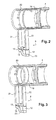
- FIGs 2 and 3 is shown a longitudinal section of a magnetic circuit integrated in a master cylinder of the invention.
- the master cylinder (not shown in Figures 2 and 3), is a master cylinder with holes dilation.
- the master cylinder can also be a master cylinder with valve, or any other known master cylinder.
- the piston 4 is provided with an expansion hole 20.
- the magnetic circuit 9 is formed, in Figures 2 and 3, by three pole pieces 21, 22 and 23 fixed.
- the pole pieces 21, 22 and 23 form for example a U.
- the pole pieces 21 and 22 form two branches of the U, and are perpendicular to the piston 4.
- the pole piece 23 forms a base of the U, parallel to the piston 4.
- the magnet 12 is, for example, housed in a space formed between a lower end of the pole piece 22 and the pole piece 23.
- the magnetic detector 13 is, for example, housed in a space formed between a lower end of the pole piece 21 and the pole piece 23.
- the lower end of a pole piece, 21 and 22, means the end further from the piston 4.
- the mobile magnetic part 19 is formed by a muff.
- the sleeve 19 is for example molded in the piston 4, at proximity of the expansion hole 20, on the side of a push rod, that is to say on the side opposite a master cylinder bottom.
- the sleeve 19 can also be mounted in the piston.
- the brake lights must remain on for all the duration of braking.
- the moving part 19 must therefore be sufficiently long so that the magnetic circuit is closed during all braking, i.e. during the entire advance of the piston 4 in the bore.
- the stop lights do not do not go out unexpectedly in the middle of braking. They must also remain on for the entire duration of return to the master rest position cylinder, i.e. during the entire deceleration time of the vehicle, until stopping or accelerating again.
- the length of the moving part 19 must therefore be substantially equal to a useful stroke of the piston 4.
- the piston 4 When the brake pedal is released, the piston 4 returns to the position rest, bringing with it the moving part 19.
- the magnetic circuit 9 is then open again.
- the value of the magnetic field measured by the sensor 13 varies.
- the sensor 13 controls the extinction of the brake lights at electrical system.
- the magnetic circuit 9 is stationary.
- the magnetic piece 19 is mobile and comes to close the magnetic circuit 9 during braking. The fires of stop are then lit.
- the moving part 19 moves even before the pressure builds up in the master cylinder chamber.
- the variation of the magnetic field measured by the sensor 13 takes place even before braking. So we have early detection of braking, and lighting of brake lights synchronize with braking.
- FIG 3 is shown another embodiment of the invention.
- the moving part 19 is molded inside the piston 4.
- the moving part 19, in FIG. 3, is formed by a ring 19.
- the ring 19 is, for example, arranged near the expansion hole 20.
- the magnetic circuit 9 is positioned opposite the ring 19. That is to say that the ring 19 closes the magnetic circuit 9 when the master cylinder is resting.
- the value of the magnetic field is measured by the sensor 13.
- the sensor 13 sends information to an electrical system (not shown) which controls the switching off or switching on of the brake lights.
- the magnetic circuit 9 is open.
- the opening of the magnetic circuit 9 is accompanied by a brake lights come on.
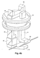
- FIGS 4a and 4b show a particular embodiment of the invention.
- the sensor is fitted with a flexible reed switch (ILS).
- the ILS circuit is for example contained in a bulb 28.
- the magnetic circuit comprises three pole pieces 29, 30 and 31, fixed.
- the pole pieces 29, 30 and 31 are mutually parallel and perpendicular to a body 33 of master cylinder.
- One of the three pole pieces 30 ends, at an end opposite to the master cylinder, by a base 35.
- a moving magnetic part (not visible) is housed in the piston 34, or inside the piston 34.
- the moving part is opposite the pole pieces 29 and 30.
- the moving part is distant from the pole pieces 29, 30 and 31 when the piston 34 is not activated.
- an ILS detector Since an ILS detector is very sensitive to magnetic flux, it is better to have no magnetic field, or a magnetic field the as low as possible, in the circuit containing the bulb 28 when a piston 34 of the master cylinder is in the rest position, in order to ensure operation safest detection.
- two magnetic circuits are used.
- a first magnetic circuit formed by two pole pieces 29 and 30, is housed a magnet 32.
- the magnet is located between one end bottom of the pole piece 29 and the base 35 of the pole piece 30.
- a second circuit formed by the pole piece 29 and the piece polar 31, is housed the bulb ILS 28. In this second circuit does not circulate no magnetic flux when the piston 34 is not actuated.
- An advance of the piston 34 leads to an advance of the part moving magnetic, which approaches the pole pieces 29 and 30 and then the pole piece 31.
- a magnetic flux circulates in the first circuit, then in the second.
- the sum of the first and second air gaps 26 and 27 is less than the sum of the first, second and third air gap 26, 25, 24. Even more advantageously, the sum of the first and second air gaps 26 and 27 is strictly greater than the sum of the first, second and third air gaps 26, 25, 24.
- the ILS 28 bulb contained in the circuit formed by the parts polar 29 and 31, is perfectly isolated from any residual magnetic flux when the piston 34 is not actuated.
- the magnetic circuit containing the magnet 32, for its part, allows a residual magnetic flux to circulate. As soon as the piston 34 advances, the magnetic circuit comprising the bulb 28 is closed and a magnetic flux can flow through it.
- the sensor or magnetic detector, can also be constituted by a Hall effect cell, or a magneto-resistive cell (AMR, GMR).
- AMR magneto-resistive cell
- the moving part can be molded, overmolded or fixed on the piston.
- the part mobile is molded or fixed in the piston.
- the moving part can be, for example, overmolded in a plastic piston.
- an outer contour of the piston is perfectly smooth.
- the sealing cup is housed in a bore in the master cylinder.
- the bore is open partially at the level of a pressure chamber in which the piston.
- the polarized magnet can be of material with low magnetic loss in AlNiCo or samarium-cobalt type temperature.
- the master cylinder can be manufactured in any non-magnetic material, such as aluminum.
- the pole piece and the movable element, forming the magnetic circuit are for example made of ferromagnetic materials.
- the pole pieces are for example made of conventional steel type XC10, or steel with high ferromagnetic properties X6CrNiMoTi17-12-2 or X5CrNiMo17-12-2, as marketed by the company Sandvik (reference: R Fe 80 C).
- Such a sensor can be used for all functions requiring know the position of one piece in relation to another.
Landscapes
- Engineering & Computer Science (AREA)
- Mechanical Engineering (AREA)
- Transportation (AREA)
- Physics & Mathematics (AREA)
- General Physics & Mathematics (AREA)
- General Engineering & Computer Science (AREA)
- Fluid Mechanics (AREA)
- Transmission Of Braking Force In Braking Systems (AREA)
- Measurement Of Length, Angles, Or The Like Using Electric Or Magnetic Means (AREA)
- Braking Systems And Boosters (AREA)
- Valves And Accessory Devices For Braking Systems (AREA)
- Braking Arrangements (AREA)
- Regulating Braking Force (AREA)
Applications Claiming Priority (2)
| Application Number | Priority Date | Filing Date | Title |
|---|---|---|---|
| FR0302203 | 2003-02-21 | ||
| FR0302203A FR2851538B1 (fr) | 2003-02-21 | 2003-02-21 | Maitre-cylindre de vehicule automobile avec dispositif de detection d'actionnement d'un systeme de freinage |
Publications (2)
| Publication Number | Publication Date |
|---|---|
| EP1449729A1 true EP1449729A1 (de) | 2004-08-25 |
| EP1449729B1 EP1449729B1 (de) | 2008-04-09 |
Family
ID=32732051
Family Applications (1)
| Application Number | Title | Priority Date | Filing Date |
|---|---|---|---|
| EP04003360A Expired - Lifetime EP1449729B1 (de) | 2003-02-21 | 2004-02-16 | Master-Zylinder für Kraftfahrzeuge mit einer Vorrichtung zur Ermittlung der Bremsbetätigung, insbesondere der Position des Kolbens |
Country Status (7)
| Country | Link |
|---|---|
| US (1) | US7018002B2 (de) |
| EP (1) | EP1449729B1 (de) |
| JP (1) | JP2004249985A (de) |
| AT (1) | ATE391643T1 (de) |
| DE (1) | DE602004012911T2 (de) |
| ES (1) | ES2302989T3 (de) |
| FR (1) | FR2851538B1 (de) |
Cited By (3)
| Publication number | Priority date | Publication date | Assignee | Title |
|---|---|---|---|---|
| DE10352589A1 (de) * | 2003-11-11 | 2005-06-16 | Lucas Automotive Gmbh | Hauptbremszylinder mit einer Einrichtung zur Erzeugung eines eine Betätigung des Hauptbremszylinders anzeigenden elektrischen Signals |
| FR2885108A1 (fr) * | 2005-04-28 | 2006-11-03 | Bosch Gmbh Robert | Dispositif maitre cylindre pour vehicule automobile |
| FR2921481A1 (fr) * | 2007-09-24 | 2009-03-27 | Skf Ab | Dispositif de detection de rotation et palier instrumente equipe d'un tel dispositif |
Families Citing this family (9)
| Publication number | Priority date | Publication date | Assignee | Title |
|---|---|---|---|---|
| EP2117026A4 (de) * | 2007-02-26 | 2012-03-14 | Fujikura Ltd | Magnetsensormodul und kolbenpositionsdetektionseinrichtung |
| FR2913937B1 (fr) * | 2007-03-22 | 2009-05-01 | Bosch Gmbh Robert | Procede et servomoteur destines a detecter le freinage d'un vehicule et procede de fabrication d'un tel servomoteur |
| JP4890498B2 (ja) * | 2008-05-13 | 2012-03-07 | 日信工業株式会社 | マスタシリンダにおけるピストン位置検出装置 |
| US9371064B2 (en) | 2010-06-30 | 2016-06-21 | Kelsey-Hayes Company | Position sensing assembly for use with a vehicle hydraulic master cylinder of a vehicle braking system with master cylinder assembly including such a position sensing assembly |
| KR101888453B1 (ko) * | 2011-10-13 | 2018-08-14 | 현대모비스 주식회사 | 브레이크 장치 |
| KR101913610B1 (ko) * | 2011-12-13 | 2018-10-31 | 현대모비스 주식회사 | 제동 감지 센서 |
| EP2814708B1 (de) * | 2012-02-14 | 2020-01-15 | Continental Teves AG & Co. OHG | Hauptbremszylinder mit einer vorrichtung zur berührungslosen überwachung von position und bewegung eines linear bewegbaren kolbens |
| DE102014223731A1 (de) * | 2014-11-20 | 2016-05-25 | Robert Bosch Gmbh | Sensorvorrichtung, Hydraulikaggregat zum Zusammenwirken mit der Sensorvorrichtung, Bremssystem und Verfahren zur Montage der Sensorvorrichtung |
| EP3620754B1 (de) | 2018-09-06 | 2022-01-05 | KNORR-BREMSE Systeme für Nutzfahrzeuge GmbH | Magnethalter und hubsensor mit dem magnethalter |
Citations (7)
| Publication number | Priority date | Publication date | Assignee | Title |
|---|---|---|---|---|
| US4914916A (en) * | 1988-04-04 | 1990-04-10 | Automotive Products Plc | Tandem master cylinder with electromagnetic position sensors for each piston |
| FR2713757A1 (fr) * | 1993-12-08 | 1995-06-16 | Festo Kg | Dispositif de détection de la position d'un piston. |
| US5477675A (en) * | 1989-02-17 | 1995-12-26 | Nartron Corporation | Fluid power assist method and apparatus |
| US6346806B1 (en) * | 1997-03-12 | 2002-02-12 | Pepperl +Fuchs Gmbh | Device for detecting the position of a moveable magnet to produce a magnetic field |
| WO2002036400A1 (de) * | 2000-10-31 | 2002-05-10 | Continental Teves Ag & Co. Ohg | In einen hauptzylinder integrierter signalgeber mit hall-sensor |
| DE10133163A1 (de) * | 2001-02-20 | 2002-08-29 | Bosch Gmbh Robert | Messsystem |
| EP1254819A1 (de) * | 2001-04-25 | 2002-11-06 | Delphi Technologies, Inc. | Verfahren und Vorrichtung zur Sensierung eines Bremshauptzylinders |
Family Cites Families (27)
| Publication number | Priority date | Publication date | Assignee | Title |
|---|---|---|---|---|
| US2987669A (en) * | 1959-01-19 | 1961-06-06 | Gulton Ind Inc | Hall effect electromechanical sensing device |
| DE1161698B (de) * | 1959-05-20 | 1964-01-23 | Bayer Ag | Messvorrichtung mit einer zwischen den Polen eines Magneten frei beweglichen Hallsonde |
| US3752039A (en) * | 1971-12-22 | 1973-08-14 | Ibm | Master-slave hydraulic control system |
| FR2331774A1 (fr) * | 1975-11-12 | 1977-06-10 | Radiotechnique Compelec | Procede de reperage dynamique de positions particulieres de pieces mobiles a l'aide d'un cristal a effet hall et dispositifs de mise en oeuvre du procede |
| FR2388248A1 (fr) * | 1977-04-20 | 1978-11-17 | Radiotechnique Compelec | Detecteur de position a effet hall |
| DE2945895C2 (de) * | 1979-11-14 | 1986-06-05 | Festo-Maschinenfabrik Gottlieb Stoll, 7300 Esslingen | Magnetischer Stellungsgeber für hydrauliche oder pneumatische Arbeitszylinder |
| EP0100429B1 (de) * | 1982-07-02 | 1989-08-23 | Deutsche Forschungsanstalt für Luft- und Raumfahrt e.V. | Messumformer |
| JPS5926355A (ja) * | 1982-08-05 | 1984-02-10 | Yamaha Motor Co Ltd | 油圧式ブレ−キのブレ−キスイツチ |
| JPH0240162B2 (ja) * | 1982-12-27 | 1990-09-10 | Toshiba Machine Co Ltd | Henikenshutsusochi |
| US4639665A (en) * | 1983-08-22 | 1987-01-27 | Borg-Warner Corporation | Sensing system for measuring a parameter |
| DE3410736A1 (de) * | 1984-03-23 | 1985-10-03 | Wabco Westinghouse Fahrzeug | Analoger wegsensor |
| US4855675A (en) * | 1984-05-21 | 1989-08-08 | Sacol Powerline Limited | Inductive transducers for indicating establishment of a preselected spatial relationship between two parts |
| DK195886A (da) * | 1986-04-29 | 1987-10-30 | Niels Hvilsted | Arbejdscylinder med stempel og med en magnetisk anordning til bestemmelse af en stempelposition |
| DE3713880A1 (de) * | 1987-04-25 | 1988-11-17 | Vdo Schindling | Magnetschranke |
| US4857824A (en) * | 1987-07-16 | 1989-08-15 | Cadillac Gage Textron Inc. | Movable core position transducer |
| DE9010114U1 (de) * | 1990-07-03 | 1990-09-06 | Festo KG, 7300 Esslingen | Arbeitszylinder |
| FR2691534B1 (fr) * | 1992-05-19 | 1994-08-26 | Moving Magnet Tech | Capteur de position à aimant permanent et sonde de hall. |
| US5600238A (en) * | 1994-07-05 | 1997-02-04 | Ford Motor Company | Method and apparatus for detecting the linear or rotary position of an object through the use of a variable magnetic shunt disposed in parallel with a yoke air gap |
| JPH08226826A (ja) * | 1995-02-22 | 1996-09-03 | Mikuni Corp | 磁気式位置センサ |
| JPH11211410A (ja) * | 1998-01-30 | 1999-08-06 | Matsushita Electric Ind Co Ltd | 非接触型位置センサ |
| US6304078B1 (en) * | 1998-12-09 | 2001-10-16 | Cts Corporation | Linear position sensor |
| JP2001174207A (ja) * | 1999-12-15 | 2001-06-29 | Mitsubishi Heavy Ind Ltd | 変位計及び変位量測定方法 |
| FR2825331B1 (fr) * | 2001-05-30 | 2003-09-19 | Bosch Gmbh Robert | Dispositif perfectionne de detection d'actionnement d'un systeme de freinage, et application |
| US6652039B1 (en) * | 2002-09-30 | 2003-11-25 | Robert Bosch Corporation | Anti-lock braking system with accumulator volume monitoring |
| FR2848936B1 (fr) * | 2002-12-20 | 2006-02-10 | Bosch Gmbh Robert | Maitre-cylindre comportant un dispositif de detection d'actionnement d'un systeme de freinage et vehicule comportant un tel maitre-cylindre |
| US7221151B2 (en) * | 2003-01-31 | 2007-05-22 | Delphi Technologies, Inc. | Magnetic array position sensor |
| EP1489385B1 (de) * | 2003-06-11 | 2016-07-20 | FTE automotive GmbH | Vorrichtung zur Sensierung der axialen Stellung eines ersten Bauteils, das relativ zu einem zweiten Bauteil bewegbar ist |
-
2003
- 2003-02-21 FR FR0302203A patent/FR2851538B1/fr not_active Expired - Fee Related
-
2004
- 2004-02-16 AT AT04003360T patent/ATE391643T1/de not_active IP Right Cessation
- 2004-02-16 EP EP04003360A patent/EP1449729B1/de not_active Expired - Lifetime
- 2004-02-16 ES ES04003360T patent/ES2302989T3/es not_active Expired - Lifetime
- 2004-02-16 DE DE602004012911T patent/DE602004012911T2/de not_active Expired - Lifetime
- 2004-02-17 US US10/780,326 patent/US7018002B2/en not_active Expired - Fee Related
- 2004-02-20 JP JP2004043940A patent/JP2004249985A/ja active Pending
Patent Citations (7)
| Publication number | Priority date | Publication date | Assignee | Title |
|---|---|---|---|---|
| US4914916A (en) * | 1988-04-04 | 1990-04-10 | Automotive Products Plc | Tandem master cylinder with electromagnetic position sensors for each piston |
| US5477675A (en) * | 1989-02-17 | 1995-12-26 | Nartron Corporation | Fluid power assist method and apparatus |
| FR2713757A1 (fr) * | 1993-12-08 | 1995-06-16 | Festo Kg | Dispositif de détection de la position d'un piston. |
| US6346806B1 (en) * | 1997-03-12 | 2002-02-12 | Pepperl +Fuchs Gmbh | Device for detecting the position of a moveable magnet to produce a magnetic field |
| WO2002036400A1 (de) * | 2000-10-31 | 2002-05-10 | Continental Teves Ag & Co. Ohg | In einen hauptzylinder integrierter signalgeber mit hall-sensor |
| DE10133163A1 (de) * | 2001-02-20 | 2002-08-29 | Bosch Gmbh Robert | Messsystem |
| EP1254819A1 (de) * | 2001-04-25 | 2002-11-06 | Delphi Technologies, Inc. | Verfahren und Vorrichtung zur Sensierung eines Bremshauptzylinders |
Cited By (5)
| Publication number | Priority date | Publication date | Assignee | Title |
|---|---|---|---|---|
| DE10352589A1 (de) * | 2003-11-11 | 2005-06-16 | Lucas Automotive Gmbh | Hauptbremszylinder mit einer Einrichtung zur Erzeugung eines eine Betätigung des Hauptbremszylinders anzeigenden elektrischen Signals |
| DE10352589B4 (de) * | 2003-11-11 | 2005-09-08 | Lucas Automotive Gmbh | Hauptbremszylinder mit einer Einrichtung zur Erzeugung eines eine Betätigung des Hauptbremszylinders anzeigenden elektrischen Signals |
| FR2885108A1 (fr) * | 2005-04-28 | 2006-11-03 | Bosch Gmbh Robert | Dispositif maitre cylindre pour vehicule automobile |
| FR2921481A1 (fr) * | 2007-09-24 | 2009-03-27 | Skf Ab | Dispositif de detection de rotation et palier instrumente equipe d'un tel dispositif |
| WO2009040345A1 (en) * | 2007-09-24 | 2009-04-02 | Aktiebolaget Skf | Device for detecting rotation and instrumented bearing fitted with such a device |
Also Published As
| Publication number | Publication date |
|---|---|
| FR2851538A1 (fr) | 2004-08-27 |
| JP2004249985A (ja) | 2004-09-09 |
| DE602004012911D1 (de) | 2008-05-21 |
| FR2851538B1 (fr) | 2006-04-28 |
| ATE391643T1 (de) | 2008-04-15 |
| ES2302989T3 (es) | 2008-08-01 |
| US7018002B2 (en) | 2006-03-28 |
| DE602004012911T2 (de) | 2009-06-04 |
| US20040164611A1 (en) | 2004-08-26 |
| EP1449729B1 (de) | 2008-04-09 |
Similar Documents
| Publication | Publication Date | Title |
|---|---|---|
| EP1449729B1 (de) | Master-Zylinder für Kraftfahrzeuge mit einer Vorrichtung zur Ermittlung der Bremsbetätigung, insbesondere der Position des Kolbens | |
| EP1042155B1 (de) | Kugelgelenk für eine kraftfahrzeuglenkung | |
| FR2565920A1 (fr) | Systeme de freins a amplification hydraulique de l'effort de freinage | |
| FR2586222A1 (fr) | Servo de frein pneumatique | |
| EP2407361A1 (de) | Hauptbremszylindervorrichtung für Kraftfahrzeug | |
| FR2648097A1 (fr) | Maitre-cylindre, notamment pour systeme de freinage hydraulique antiblocage | |
| FR2885108A1 (fr) | Dispositif maitre cylindre pour vehicule automobile | |
| EP0353117B2 (de) | Vorrichtung zur Messung der Stellung eines beweglichen Gliedes innerhalb eines festen Gliedes | |
| FR2667545A1 (fr) | Dispositif d'adaptation d'un element moteur a un attelage pour vehicule routier. | |
| FR2663598A1 (fr) | Servomoteur d'assistance a depression. | |
| FR2825331A1 (fr) | Dispositif perfectionne de detection d'actionnement d'un systeme de freinage, et application | |
| FR2848936A1 (fr) | Maitre-cylindre comportant un dispositif de detection d'actionnement d'un systeme de freinage et vehicule comportant un tel maitre-cylindre | |
| EP1253057B1 (de) | Vorrichtung zur Erkennung der Betätigung einer Bremsanlage und ihrer Anwendung | |
| EP3264431B1 (de) | Bistabiler linearer elektromagnet | |
| EP1635149B1 (de) | Einrichtung zur optischen Detektion der Betätigung der Bremsen eines Fahrzeugs | |
| FR2731398A1 (fr) | Actionneur a declenchement pilote de manoeuvre d'un organe, par exemple de vehicule automobile | |
| FR2860476A1 (fr) | Dispositif de commande des feux de freinage d'un vehicule automobile. | |
| FR2524108A1 (fr) | Soupape hydraulique avec controle de position | |
| FR2834255A1 (fr) | Dispositif de commande des feux de freinage sur un vehicule automobile | |
| FR2532900A1 (fr) | Valve de retenue de pression pour systeme de freinage de vehicule automobile | |
| FR2632912A1 (fr) | Ensemble d'un maitre-cylindre et d'un compensateur hydraulique | |
| EP2058196B1 (de) | Taster für Hilfsservomotor zur Bremsung | |
| FR2647070A1 (fr) | Systeme de blocage d'un organe mobile de commande manuelle dans une position predeterminee | |
| FR2872767A1 (fr) | Maitre-cylindre comportant des moyens de detection du deplacement d'un element mobile | |
| FR2825056A1 (fr) | Servomoteur d'assistance pneumatique au freinage a hauteur de saut variable |
Legal Events
| Date | Code | Title | Description |
|---|---|---|---|
| PUAI | Public reference made under article 153(3) epc to a published international application that has entered the european phase |
Free format text: ORIGINAL CODE: 0009012 |
|
| AK | Designated contracting states |
Kind code of ref document: A1 Designated state(s): AT BE BG CH CY CZ DE DK EE ES FI FR GB GR HU IE IT LI LU MC NL PT RO SE SI SK TR |
|
| AX | Request for extension of the european patent |
Extension state: AL LT LV MK |
|
| 17P | Request for examination filed |
Effective date: 20050225 |
|
| AKX | Designation fees paid |
Designated state(s): AT BE BG CH CY CZ DE DK EE ES FI FR GB GR HU IE IT LI LU MC NL PT RO SE SI SK TR |
|
| 17Q | First examination report despatched |
Effective date: 20050620 |
|
| 17Q | First examination report despatched |
Effective date: 20050620 |
|
| GRAP | Despatch of communication of intention to grant a patent |
Free format text: ORIGINAL CODE: EPIDOSNIGR1 |
|
| GRAS | Grant fee paid |
Free format text: ORIGINAL CODE: EPIDOSNIGR3 |
|
| GRAA | (expected) grant |
Free format text: ORIGINAL CODE: 0009210 |
|
| AK | Designated contracting states |
Kind code of ref document: B1 Designated state(s): AT BE BG CH CY CZ DE DK EE ES FI FR GB GR HU IE IT LI LU MC NL PT RO SE SI SK TR |
|
| REG | Reference to a national code |
Ref country code: GB Ref legal event code: FG4D Free format text: NOT ENGLISH |
|
| REG | Reference to a national code |
Ref country code: CH Ref legal event code: EP |
|
| REG | Reference to a national code |
Ref country code: IE Ref legal event code: FG4D Free format text: LANGUAGE OF EP DOCUMENT: FRENCH |
|
| REF | Corresponds to: |
Ref document number: 602004012911 Country of ref document: DE Date of ref document: 20080521 Kind code of ref document: P |
|
| REG | Reference to a national code |
Ref country code: ES Ref legal event code: FG2A Ref document number: 2302989 Country of ref document: ES Kind code of ref document: T3 |
|
| PG25 | Lapsed in a contracting state [announced via postgrant information from national office to epo] |
Ref country code: SI Free format text: LAPSE BECAUSE OF FAILURE TO SUBMIT A TRANSLATION OF THE DESCRIPTION OR TO PAY THE FEE WITHIN THE PRESCRIBED TIME-LIMIT Effective date: 20080409 |
|
| NLV1 | Nl: lapsed or annulled due to failure to fulfill the requirements of art. 29p and 29m of the patents act | ||
| PG25 | Lapsed in a contracting state [announced via postgrant information from national office to epo] |
Ref country code: PT Free format text: LAPSE BECAUSE OF FAILURE TO SUBMIT A TRANSLATION OF THE DESCRIPTION OR TO PAY THE FEE WITHIN THE PRESCRIBED TIME-LIMIT Effective date: 20080909 Ref country code: BG Free format text: LAPSE BECAUSE OF FAILURE TO SUBMIT A TRANSLATION OF THE DESCRIPTION OR TO PAY THE FEE WITHIN THE PRESCRIBED TIME-LIMIT Effective date: 20080709 Ref country code: FI Free format text: LAPSE BECAUSE OF FAILURE TO SUBMIT A TRANSLATION OF THE DESCRIPTION OR TO PAY THE FEE WITHIN THE PRESCRIBED TIME-LIMIT Effective date: 20080409 Ref country code: NL Free format text: LAPSE BECAUSE OF FAILURE TO SUBMIT A TRANSLATION OF THE DESCRIPTION OR TO PAY THE FEE WITHIN THE PRESCRIBED TIME-LIMIT Effective date: 20080409 |
|
| PG25 | Lapsed in a contracting state [announced via postgrant information from national office to epo] |
Ref country code: AT Free format text: LAPSE BECAUSE OF FAILURE TO SUBMIT A TRANSLATION OF THE DESCRIPTION OR TO PAY THE FEE WITHIN THE PRESCRIBED TIME-LIMIT Effective date: 20080409 |
|
| REG | Reference to a national code |
Ref country code: IE Ref legal event code: FD4D |
|
| PG25 | Lapsed in a contracting state [announced via postgrant information from national office to epo] |
Ref country code: SE Free format text: LAPSE BECAUSE OF FAILURE TO SUBMIT A TRANSLATION OF THE DESCRIPTION OR TO PAY THE FEE WITHIN THE PRESCRIBED TIME-LIMIT Effective date: 20080709 Ref country code: IE Free format text: LAPSE BECAUSE OF FAILURE TO SUBMIT A TRANSLATION OF THE DESCRIPTION OR TO PAY THE FEE WITHIN THE PRESCRIBED TIME-LIMIT Effective date: 20080409 Ref country code: DK Free format text: LAPSE BECAUSE OF FAILURE TO SUBMIT A TRANSLATION OF THE DESCRIPTION OR TO PAY THE FEE WITHIN THE PRESCRIBED TIME-LIMIT Effective date: 20080409 Ref country code: CZ Free format text: LAPSE BECAUSE OF FAILURE TO SUBMIT A TRANSLATION OF THE DESCRIPTION OR TO PAY THE FEE WITHIN THE PRESCRIBED TIME-LIMIT Effective date: 20080409 |
|
| PLBE | No opposition filed within time limit |
Free format text: ORIGINAL CODE: 0009261 |
|
| STAA | Information on the status of an ep patent application or granted ep patent |
Free format text: STATUS: NO OPPOSITION FILED WITHIN TIME LIMIT |
|
| PG25 | Lapsed in a contracting state [announced via postgrant information from national office to epo] |
Ref country code: RO Free format text: LAPSE BECAUSE OF FAILURE TO SUBMIT A TRANSLATION OF THE DESCRIPTION OR TO PAY THE FEE WITHIN THE PRESCRIBED TIME-LIMIT Effective date: 20080409 Ref country code: SK Free format text: LAPSE BECAUSE OF FAILURE TO SUBMIT A TRANSLATION OF THE DESCRIPTION OR TO PAY THE FEE WITHIN THE PRESCRIBED TIME-LIMIT Effective date: 20080409 |
|
| 26N | No opposition filed |
Effective date: 20090112 |
|
| PG25 | Lapsed in a contracting state [announced via postgrant information from national office to epo] |
Ref country code: EE Free format text: LAPSE BECAUSE OF FAILURE TO SUBMIT A TRANSLATION OF THE DESCRIPTION OR TO PAY THE FEE WITHIN THE PRESCRIBED TIME-LIMIT Effective date: 20080409 |
|
| BERE | Be: lapsed |
Owner name: ROBERT BOSCH G.M.B.H. Effective date: 20090228 |
|
| PG25 | Lapsed in a contracting state [announced via postgrant information from national office to epo] |
Ref country code: CY Free format text: LAPSE BECAUSE OF FAILURE TO SUBMIT A TRANSLATION OF THE DESCRIPTION OR TO PAY THE FEE WITHIN THE PRESCRIBED TIME-LIMIT Effective date: 20080409 Ref country code: MC Free format text: LAPSE BECAUSE OF NON-PAYMENT OF DUE FEES Effective date: 20090228 |
|
| REG | Reference to a national code |
Ref country code: CH Ref legal event code: PL |
|
| GBPC | Gb: european patent ceased through non-payment of renewal fee |
Effective date: 20090216 |
|
| PG25 | Lapsed in a contracting state [announced via postgrant information from national office to epo] |
Ref country code: CH Free format text: LAPSE BECAUSE OF NON-PAYMENT OF DUE FEES Effective date: 20090228 Ref country code: LI Free format text: LAPSE BECAUSE OF NON-PAYMENT OF DUE FEES Effective date: 20090228 |
|
| PG25 | Lapsed in a contracting state [announced via postgrant information from national office to epo] |
Ref country code: BE Free format text: LAPSE BECAUSE OF NON-PAYMENT OF DUE FEES Effective date: 20090228 |
|
| PG25 | Lapsed in a contracting state [announced via postgrant information from national office to epo] |
Ref country code: GB Free format text: LAPSE BECAUSE OF NON-PAYMENT OF DUE FEES Effective date: 20090216 |
|
| PG25 | Lapsed in a contracting state [announced via postgrant information from national office to epo] |
Ref country code: GR Free format text: LAPSE BECAUSE OF FAILURE TO SUBMIT A TRANSLATION OF THE DESCRIPTION OR TO PAY THE FEE WITHIN THE PRESCRIBED TIME-LIMIT Effective date: 20080710 |
|
| PG25 | Lapsed in a contracting state [announced via postgrant information from national office to epo] |
Ref country code: LU Free format text: LAPSE BECAUSE OF NON-PAYMENT OF DUE FEES Effective date: 20090216 |
|
| PG25 | Lapsed in a contracting state [announced via postgrant information from national office to epo] |
Ref country code: HU Free format text: LAPSE BECAUSE OF FAILURE TO SUBMIT A TRANSLATION OF THE DESCRIPTION OR TO PAY THE FEE WITHIN THE PRESCRIBED TIME-LIMIT Effective date: 20081010 |
|
| PG25 | Lapsed in a contracting state [announced via postgrant information from national office to epo] |
Ref country code: TR Free format text: LAPSE BECAUSE OF FAILURE TO SUBMIT A TRANSLATION OF THE DESCRIPTION OR TO PAY THE FEE WITHIN THE PRESCRIBED TIME-LIMIT Effective date: 20080409 |
|
| PGFP | Annual fee paid to national office [announced via postgrant information from national office to epo] |
Ref country code: FR Payment date: 20140218 Year of fee payment: 11 |
|
| REG | Reference to a national code |
Ref country code: FR Ref legal event code: ST Effective date: 20151030 |
|
| PG25 | Lapsed in a contracting state [announced via postgrant information from national office to epo] |
Ref country code: FR Free format text: LAPSE BECAUSE OF NON-PAYMENT OF DUE FEES Effective date: 20150302 |
|
| PGFP | Annual fee paid to national office [announced via postgrant information from national office to epo] |
Ref country code: IT Payment date: 20160222 Year of fee payment: 13 Ref country code: ES Payment date: 20160223 Year of fee payment: 13 |
|
| PGFP | Annual fee paid to national office [announced via postgrant information from national office to epo] |
Ref country code: DE Payment date: 20170427 Year of fee payment: 14 |
|
| PG25 | Lapsed in a contracting state [announced via postgrant information from national office to epo] |
Ref country code: IT Free format text: LAPSE BECAUSE OF NON-PAYMENT OF DUE FEES Effective date: 20170216 |
|
| REG | Reference to a national code |
Ref country code: ES Ref legal event code: FD2A Effective date: 20180629 |
|
| PG25 | Lapsed in a contracting state [announced via postgrant information from national office to epo] |
Ref country code: ES Free format text: LAPSE BECAUSE OF NON-PAYMENT OF DUE FEES Effective date: 20170217 |
|
| REG | Reference to a national code |
Ref country code: DE Ref legal event code: R119 Ref document number: 602004012911 Country of ref document: DE |
|
| PG25 | Lapsed in a contracting state [announced via postgrant information from national office to epo] |
Ref country code: DE Free format text: LAPSE BECAUSE OF NON-PAYMENT OF DUE FEES Effective date: 20180901 |