EP1449736A1 - Niedrig-Lokomotive - Google Patents
Niedrig-Lokomotive Download PDFInfo
- Publication number
- EP1449736A1 EP1449736A1 EP04003618A EP04003618A EP1449736A1 EP 1449736 A1 EP1449736 A1 EP 1449736A1 EP 04003618 A EP04003618 A EP 04003618A EP 04003618 A EP04003618 A EP 04003618A EP 1449736 A1 EP1449736 A1 EP 1449736A1
- Authority
- EP
- European Patent Office
- Prior art keywords
- locomotive
- driver
- cabs
- drive motor
- frame
- Prior art date
- Legal status (The legal status is an assumption and is not a legal conclusion. Google has not performed a legal analysis and makes no representation as to the accuracy of the status listed.)
- Granted
Links
- 230000003137 locomotive effect Effects 0.000 title claims abstract description 116
- 239000000463 material Substances 0.000 claims description 7
- 230000005540 biological transmission Effects 0.000 abstract description 10
- 239000002828 fuel tank Substances 0.000 description 10
- 238000010276 construction Methods 0.000 description 9
- 239000003921 oil Substances 0.000 description 8
- 238000001816 cooling Methods 0.000 description 4
- 238000010438 heat treatment Methods 0.000 description 4
- 230000003584 silencer Effects 0.000 description 4
- 238000005253 cladding Methods 0.000 description 2
- 238000002485 combustion reaction Methods 0.000 description 2
- 230000008878 coupling Effects 0.000 description 2
- 238000010168 coupling process Methods 0.000 description 2
- 238000005859 coupling reaction Methods 0.000 description 2
- 239000012530 fluid Substances 0.000 description 2
- 239000000446 fuel Substances 0.000 description 2
- 239000007789 gas Substances 0.000 description 2
- 239000007788 liquid Substances 0.000 description 2
- 238000000034 method Methods 0.000 description 2
- 230000001960 triggered effect Effects 0.000 description 2
- XLYOFNOQVPJJNP-UHFFFAOYSA-N water Substances O XLYOFNOQVPJJNP-UHFFFAOYSA-N 0.000 description 2
- 239000000969 carrier Substances 0.000 description 1
- 239000000295 fuel oil Substances 0.000 description 1
- 230000002706 hydrostatic effect Effects 0.000 description 1
- 238000009434 installation Methods 0.000 description 1
- 238000003825 pressing Methods 0.000 description 1
- 239000010729 system oil Substances 0.000 description 1
Images

Classifications
-
- B—PERFORMING OPERATIONS; TRANSPORTING
- B61—RAILWAYS
- B61C—LOCOMOTIVES; MOTOR RAILCARS
- B61C17/00—Arrangement or disposition of parts; Details or accessories not otherwise provided for; Use of control gear and control systems
- B61C17/04—Arrangement or disposition of driving cabins, footplates or engine rooms; Ventilation thereof
Definitions
- the present invention relates to a locomotive, such as that used for track construction work is used, and strictly speaking it affects a low-set diesel locomotive and their use for transporting track material.
- a so-called gantry crane is usually used to build tracks on the left and right next to the track to be built, provisionally arranged (makeshift) Rails moved.
- the yokes to be installed (rails connected to the Threshold) are available on wagons, with a single yoke total length of has about 120 m.
- the gantry crane moves slowly (walking pace) back to the wagons and takes up one new yoke each.
- the resulting working method is that the gantry crane can only move at walking pace very slow and the time involved is very high.
- the invention is therefore based on the object of a locomotive for track construction work To provide that can run under a gantry crane in the aforementioned sense and which has the required tensile force to yoke when laying the track material to be able to pull loaded wagons under the gantry crane.
- a locomotive is used to achieve this object proposed, which comprises a locomotive frame, two spaced apart multi-axle bogies that are attached to the locomotive frame, also a gearbox and a drive motor located above one of the bogies on the locomotive frame is attached, a cab that consists of two separate cabs, the left and are attached to the right of the body of the locomotive, as well as a hydraulic device, to drive the cabs up and down.
- a total height that is less than 2.55 m (gantry crane height) is allowed to drive under the gantry crane.
- the locomotive according to the invention is therefore designed such that it is low overall is set, the cabs can be lowered so that their roof then lies approximately at the level of the low-lying body of the locomotive. On in this way the locomotive can load the wagons loaded with yokes under the gantry crane pull through and carry to the front end of the track construction work.
- the on provisionally laid rails very slow running gantry crane then no longer needs drive back to take up a new yoke, but only forward, and in the course of the progress of the track construction work. Compared to the previous one Workflow is thus through the use of the locomotive according to the invention Track laying achieved a time saving of around 35%.
- Another advantage compared to known locomotives is that as a result of the driver's cabs provided on both sides of the locomotive Can control the locomotive from any side.
- Another advantage compared to Known locomotives is that the locomotive is used for other work or the driver's cabs are raised again during normal journeys can, so that the view or overview is given as usual.
- the drive motor can be a diesel engine his. This can also be offset from the center such that the bogie has sufficient running freedom, in this case due to the speed Intermediate gear between the drive motor and the gear is connected.
- the drive motor is advantageously offset 80 mm from the center.
- the locomotive can be used at Driver's cabs driven below have a height of 2.32 m.
- the hydraulic device can be according to yet another optional feature the invention can be provided on one side only.
- the hydraulic advantageously comprises Set up a hydraulic pump.
- the bogies can be biaxial his.
- driver's cabs can optionally each include a driver's desk.
- the connection between the respective driver's desk and a driver's brake valve or an additional brake valve is advantageously kept elastic. This is preferably done using Separate, elastic rubber pipe connections implemented for each control stand.
- driver's cabs can move in the same direction or in opposite directions Directions.
- the use of the locomotive for Transport of track material provided.
- the locomotive according to the invention runs when the driver's cab is lowered, it passes under a gantry crane and pulls wagons loaded with yokes under it.
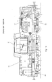
- Figures 1A and 1B show a diesel locomotive 20 of the prior art.
- FIGS. 1A, 1B Behind the rear, i.e. 1A, 1B on the right indicated cladding next to the diesel engine 1 there is also a cooler group 8.
- Two fuel tanks 10, only one of which is shown are in the middle of the locomotive next to the frame side members accommodated.
- the liquid gear 2 is under the cab in the Frame carriers hooked in.
- the cab 21 is mounted on rubber profiles and has two opposite control panels 17, one of which is shown.
- the diesel engine 1 shown in FIGS. 1A and 1B has an intake turbine and via a correspondingly suitable engine mounting, through which the engine on the locomotive frame 22 is attached.
- the required combustion air is through an air filter 5 and Suction hoses supplied.
- the exhaust gases are through a silencer 4 on the front side of the cab 21 derived upwards.
- the exhaust shaft 15 serves as additional silencer.
- the diesel system consists of two (main) fuel tanks 10 and a small one at the top lying fuel tank 11.
- the fuel is in this small tank a pump from the main containers lying between the frame supports and so the engine is fueled.
- the diesel engine 1 is connected to the fluid transmission via an elastic coupling and a cardan shaft 2 connected.
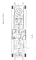
- the flanges of the drive shaft are symmetrical to Middle of the locomotive. From there the next wheelsets of the bogies 19 driven by cardan shafts. From here, the outer wheelsets are also over PTO shafts driven.
- the known diesel locomotive 20 shown has a multi-release locomotive brake.
- wheel / rail closes the locomotive a sanding system a, which is triggered by electro-pneumatic valves.
- the compressed air required is sucked in via an electrically operated compressed air compressor 14 and in air containers saved.
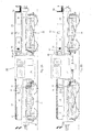
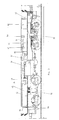
- FIGS. 2A, 2B and 2C show an embodiment of a locomotive according to the present invention.
- the locomotive according to the invention differs from the prior art in particular in that instead of the usual height of 4.25 m, such as a Locomotive series 211 (without horn) has a height of only about 2.32 m when the cabs are in the lowered position.
- the vehicle part of the locomotive according to the invention and shown in FIGS. 2A, 2B and 2C 30 essentially consists of a locomotive frame 34, a left and driver's cab 31 arranged on the right, which can be moved hydraulically in height, a low front 32 and rear stem 33, front and rear Weight 51 or 52 and two biaxial bogies 35.
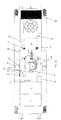
- FIG. 4A Under the lining of the front stem 33 shown in FIG. 4A an electrically operated air compressor 53 and a fuel tank 45 are arranged. Behind the fairing of the rear stem 32 is next to the diesel engine 40 still a fan system with cooling devices 42. Components such as a Fuel oil tank 9, a boiler feed water tank 12, a heating steam boiler 13, a three-circuit heat exchanger 6, etc., as shown in Figures 1A and 1B, serve at the known mainline diesel locomotive shown there only the heating of the train and can therefore be omitted from the (track construction) locomotive 30 according to the invention become.
- Components such as a Fuel oil tank 9, a boiler feed water tank 12, a heating steam boiler 13, a three-circuit heat exchanger 6, etc., as shown in Figures 1A and 1B, serve at the known mainline diesel locomotive shown there only the heating of the train and can therefore be omitted from the (track construction) locomotive 30 according to the invention become.
- the locomotive frame 34 of the locomotive 30 according to the invention is supported also like the locomotive frame 22 of the diesel locomotive shown in FIGS. 1A, 1B 20 at four points on two coil springs on the bogies 35.
- the diesel engine 40 shown in Figure 2C is from the center (from the cab to the Figures 2A-2C seen from the right side) so that the underlying Bogie 35 with a reduced overall height of the locomotive sufficient running freedom having.
- the diesel engine is approximately 80 mm offset in the aforementioned sense.
- Manufacturer of the 1000 HP installed here strong engine (2100 rpm) is Caterpillar Inc., Illinois, USA.
- the engine is over one suitable engine mounting (not shown) attached to the locomotive frame 34.
- the aforementioned transmission 41 is a turbo / converter transmission from Voith Turbo GmbH & Co. KG, Heidenheim (Voith liquid gear L216 rs).
- the Intermediate gear 48 is with a gear reduction from 2000 to 1500 revolutions / min constructed.
- the intermediate gear 48 is connected to the via an elastic coupling and a propeller shaft Gear 41 connected, which is suspended in the frame supports.
- the flanges of the Drive shaft are symmetrical as in the known locomotive described above to the center of the locomotive, with the next wheelsets of the bogies 35 are driven by cardan shafts. From here the outer wheelsets also driven by cardan shafts, as shown in Figure 3.
- a transmission oil heat exchanger 49 is attached to the side of the diesel engine.
- the Fuel tank 45 of the locomotive according to the invention, the engine 40 with fuel is located next to the driver's cabs 31 in the front stem 32 of the locomotive.
- a 24V (2x12V) battery 36 is arranged next to the fuel tank 45.
- the required combustion air is the diesel engine 40 on the right and Air filter 46 and corresponding suction hoses (not shown) supplied.
- the exhaust gases are symmetrical about the longitudinal axis of the locomotive lying silencer 47 derived upwards, as can be seen in Figure 3.
- the greatest permissible speed of the locomotive according to the invention is in Overdrive 100 km / h and slow speed 65 km / h.
- the desired gear can be via a reversing lever 57 shown in FIG. 2C.
- FIG. 2C there are 33 in the rear stem next to the motor 40 a fan system with cooling devices 42 and a fan wheel 43 connected downstream (Behr GmbH & Co., Stuttgart) installed, which are adapted to the required To provide cooling capacity for the engine.
- a fan wheel 43 is a hydrostatic Drive provided, consisting of an oil motor (not shown) and a fan pump 44 (pressure oil pump), which is driven by V-belts from the gearbox 41 and from the Fan system oil tank 50 is supplied with oil.
- the control of the diesel engine 40, gear 41 and reduction gear 48 takes place via one of two operator consoles 37.
- This control is an electro-pneumatic one System, i.e. a shift lever turns a series of solenoid valves actuated by the pneumatic mounted on the motor 40 and on the gearboxes 41 and 48 Control systems the control air is allocated.
- the braking system of the locomotive according to the invention essentially corresponds to that of the known locomotive described above. It has four double brake cylinders, each unit being located between the wheelsets on the bogie frame and consists of a cylinder with two oppositely pressing pistons.
- the sanding system of the locomotive 30 is via electro-pneumatic valves 55 triggered.
- the compressed air required is supplied by a mechanically driven compressed air compressor 53 sucked in.
- the air compressor or air compressor 53 runs and fills Air (for the brakes) in the air tanks.
- Air for the brakes
- the compressed air compressor runs empty until air is needed again. The valve then switches on automatically.
- a side brake 56 acts only on a bogie 35 and can from be operated outside.
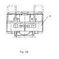
- the cab is divided, the two cabs 31 left and right on the body of the locomotive 30 approximately at the level of the gear 41, 48 and are attached between the two biaxial bogies 35.
- the Driver's cabs can be hydraulically raised and lowered using a hydraulic pump 54 be driven below, as indicated in Figures 4A and 4B in dashed lines is. In the present example, this hydraulic system can only be installed on one side but can also be double-sided if required.
- Each driver's cab 31 has a driver's desk 37, next to which one Driver brake valve 38 and an additional brake valve 39 are arranged, as shown in Figure 2C is shown.
- Driver consoles 37 give the locomotive driver the opportunity to get the locomotive from everyone To control side.
- the two parts of the cab can also be "mirror-symmetrical" arranged driver's consoles 37, which has the advantage that the locomotive driver always on the same in the direction of travel, for example the right side.
- the electrical Facilities are housed in equipment cabinets 58 opposite each other the driver's desks are attached.
- the low-locomotive according to the invention which was developed especially for laying the track is by reducing the body height and the possibility of opening and lowering the Driver's cabs are designed in such a way that when laying the track material, those with Jochen loaded wagons can pull under the gantry crane.
- the locomotive driver or during normal route travel furthermore the possibility to start up the driver's cabs.
- the view or overview of the The route is still available as usual.
- a gantry crane When building the track, a gantry crane runs on the left and right next to the track to be built provisionally arranged rails.
- the yokes i.e. each finished with the threshold connected rails, are ready on wagons.
- the gantry crane moves slowly (walking pace) from its work location back to the Wagons and each takes on a new yoke. Since the crane is moving very slowly this way of working is very time-consuming and correspondingly high costs connected.
- the low locomotive according to the invention allows the required wagons with the yokes to be laid to the place of use so that the gantry crane no longer has to drive back, but only forward, in the course of Progress of track construction work.
- the driver's cabs 31 attached to the side of the locomotive are approximately on the Lower the height of the low body so that the locomotive is under the Drive through the gantry crane and the wagons loaded with yokes under the gantry crane can pull through.
- the locomotive adapted in this way then runs under the gantry crane through and the gantry crane picks up a new yoke from the wagons and sets it at the desired location. As the track construction progresses repeated the above steps.
- Locomotive achieved a time saving of around 35% when laying the track.
Landscapes
- Engineering & Computer Science (AREA)
- Automation & Control Theory (AREA)
- Transportation (AREA)
- Mechanical Engineering (AREA)
- Control Of Vehicle Engines Or Engines For Specific Uses (AREA)
- Motor Power Transmission Devices (AREA)
- Arrangement Or Mounting Of Propulsion Units For Vehicles (AREA)
- Lubricants (AREA)
- Diaphragms For Electromechanical Transducers (AREA)
- Machines For Laying And Maintaining Railways (AREA)
Abstract

Description
- 1
- Dieselmotor
- 2
- Flüssigkeitsgetriebe
- 4
- Schalldämpfer
- 5
- Luftfilter
- 6
- Dreikreis-Wärmetauscher
- 7
- Getriebeölwärmetauscher
- 8
- Kühlergruppe mit Lüfterrad
- 9
- Heizölbehälter
- 10
- Kraftstoffbehälter
- 11
- Kraftstoffbetriebsbehälter
- 12
- Kesselspeisewasserbehälter
- 13
- Heizdampfkessel
- 14
- Druckluftkompressor
- 15
- Auspuffschacht
- 16
- Lüfterpumpe
- 17
- Führerpult und -sitz
- 19
- Drehgestelle
- 20
- Diesellokomotive
- 21
- Führerhaus
- 22
- Lokomotivrahmen
- 23
- Schaltschränke für Elektrik und Heizung
- 30
- (Niedrig-) Lokomotive
- 31
- Führerstand links und rechts
- 32
- Vorderer Vorbau
- 33
- Hinterer Vorbau
- 34
- Lokomotivrahmen
- 35
- Drehgestelle
- 36
- Batterie 24V
- 37
- Führerpult
- 38
- Führerbremsventil
- 39
- Zusatzbremsventil
- 40
- Dieselmotor
- 41
- Getriebe
- 42
- Lüfteranlage mit Kühlvorrichtungen
- 43
- Lüfterrad
- 44
- Lüfterpumpe
- 45
- Kraftstoffbehälter
- 46
- Luftfilter für den Dieselmotor
- 47
- Abgas-Schalldämpfer
- 48
- (Zwischen-) Getriebe
- 49
- Getriebeölwärmetauscher
- 50
- Lüfteranlageölbehälter
- 51
- Gewicht
- 52
- Gewicht
- 53
- Druckluftkompressor
- 54
- Hydraulikpumpe
- 55
- Elektro-pneumatisches Ventil
- 56
- Handbremse
- 57
- Wendeschalthebel 65/100 km/h
- 58
- Apparateschrank für elektrische Anlage
Claims (13)
- Lokomotive (30) zum Transportieren von Gleismaterial, wobei die Lokomotive einen Lokomotivrahmen (34) umfasst, zwei voneinander beabstandete mehrachsige Drehgestelle (35), die am Lokomotivrahmen (34) angebracht sind, ein Getriebe (41), einen Antriebsmotor (40), der oberhalb eines der Drehgestelle (35) auf dem Lokomotivrahmen befestigt ist, ein Führerhaus, das aus zwei Führerständen (31) besteht, die links und rechts an dem Korpus der Lokomotive (30) angesetzt sind, sowie eine hydraulische Einrichtung, um die Führerstände (31) nach oben und unten zu fahren, wobei die Lokomotive bei nach unten gefahrenen Führerständen (31) eine Gesamthöhe aufweist, die geringer als 2,55 m ist.
- Lokomotive nach Anspruch 1, wobei der Antriebsmotor (40) ein Dieselmotor ist.
- Lokomotive nach Anspruch 2, wobei der Antriebsmotor (40) derart aus dem Zentrum versetzt ist, dass das Drehgestell (35) hinreichende Lauffreiheit aufweist, und wobei zwischen den Antriebsmotor (40) und das Getriebe (41) ein Zwischengetriebe (48) geschaltet ist.
- Lokomotive nach Anspruch 3, wobei der Antriebsmotor (40) 80 mm aus dem Zentrum versetzt ist.
- Lokomotive nach einem der Ansprüche 1 bis 4, wobei die Lokomotive bei nach unten gefahrenen Führerständen (31) eine Höhe von 2,32 m aufweist.
- Lokomotive nach einem der vorstehenden Ansprüche, wobei die hydraulische Einrichtung nur auf einer Seite vorgesehen ist.
- Lokomotive nach einem der vorstehenden Ansprüche, wobei die hydraulische Einrichtung eine Hydraulikpumpe (54) umfasst.
- Lokomotive nach einem der vorstehenden Ansprüche, wobei die Drehgestelle (35) zweiachsig sind.
- Lokomotive nach einem der vorstehenden Ansprüche, wobei die Führerstände (31) jeweils ein Führerpult (37) umfassen.
- Lokomotive nach Anspruch 9, wobei die Verbindung zwischen dem jeweiligen Führerpult (37) und einem Führerbremsventil (38) bzw. einem Zusatzbremsventil (39) elastisch gehalten ist.
- Lokomotive nach einem der vorstehenden Ansprüche, wobei die Führerstände (31) in die gleiche Richtung ausgerichtet sind.
- Lokomotive nach einem der vorstehenden Ansprüche, wobei die Führerstände (31) in entgegengesetzte Richtungen ausgerichtet sind.
- Verwendung einer Lokomotive nach einem der Ansprüche 1 bis 12 zum Transportieren von Gleismaterial, wobei die Lokomotive (30) bei nach unten gefahrenen Führerständen (31) unter einem Portalkran durchfährt und mit Jochen beladene Waggons unter dem Portalkran durchzieht.
Applications Claiming Priority (2)
| Application Number | Priority Date | Filing Date | Title |
|---|---|---|---|
| DE10306976 | 2003-02-19 | ||
| DE10306976A DE10306976A1 (de) | 2003-02-19 | 2003-02-19 | Niedrig-Lokomotive |
Publications (2)
| Publication Number | Publication Date |
|---|---|
| EP1449736A1 true EP1449736A1 (de) | 2004-08-25 |
| EP1449736B1 EP1449736B1 (de) | 2005-10-12 |
Family
ID=32731049
Family Applications (1)
| Application Number | Title | Priority Date | Filing Date |
|---|---|---|---|
| EP04003618A Expired - Lifetime EP1449736B1 (de) | 2003-02-19 | 2004-02-18 | Niedrig-Lokomotive |
Country Status (3)
| Country | Link |
|---|---|
| EP (1) | EP1449736B1 (de) |
| AT (1) | ATE306411T1 (de) |
| DE (2) | DE10306976A1 (de) |
Cited By (3)
| Publication number | Priority date | Publication date | Assignee | Title |
|---|---|---|---|---|
| AT503148B1 (de) * | 2005-11-30 | 2011-07-15 | Siemens Ag | Anbindung eines schweren gerätes an einer tragstruktur eines schienenfahrzeuges |
| AT503149B1 (de) * | 2005-11-30 | 2011-12-15 | Siemens Ag | Einbau eines schweren gerätes in die tragstruktur eines schienenfahrzeuges |
| WO2019029059A1 (zh) * | 2017-08-08 | 2019-02-14 | 中车大连机车车辆有限公司 | 自动调节机车名义牵引点高度的控制方法 |
Citations (6)
| Publication number | Priority date | Publication date | Assignee | Title |
|---|---|---|---|---|
| DE1217802B (de) * | 1964-12-28 | 1966-05-26 | Buessing Automobilwerke Ag | Strassenfahrzeug zum Transport von Stueckguetern |
| DE1260995B (de) * | 1964-01-28 | 1968-02-08 | Alfred Achammer Dipl Ing | Kraftfahrzeuge |
| US3431016A (en) * | 1966-01-07 | 1969-03-04 | Landsverk Ab | Method of reducing the profile of a vehicle |
| US3885643A (en) * | 1970-07-31 | 1975-05-27 | Unit Rig & Equip | Elevatable cab for vehicles |
| WO1983000666A1 (en) * | 1981-08-26 | 1983-03-03 | Alge Bjoern | A transport vehicle |
| DE29619649U1 (de) * | 1996-11-12 | 1997-05-07 | TVT Verkehrstechnologie Thüringen GmbH, 99084 Erfurt | Richtungsunabhängiges Schienenfahrzeug für Wechselbehältertransport |
Family Cites Families (6)
| Publication number | Priority date | Publication date | Assignee | Title |
|---|---|---|---|---|
| US1270628A (en) * | 1917-04-13 | 1918-06-25 | Gen Electric | Storage-battery locomotive. |
| GB337653A (en) * | 1928-12-11 | 1930-11-06 | Tatra Works Ltd | Improvements in or relating to motor vehicles |
| DE920853C (de) * | 1952-06-26 | 1954-12-02 | Krauss Maffei Ag | Steuerwelle von Motorlokomotiven |
| US3182605A (en) * | 1963-10-07 | 1965-05-11 | Lawrence J Brasher | Vehicle control |
| FR2138416B1 (de) * | 1971-05-25 | 1973-05-25 | Meca Stephanoise Const | |
| DE4424308A1 (de) * | 1994-07-09 | 1996-01-18 | Abb Patent Gmbh | Schienentriebfahrzeug |
-
2003
- 2003-02-19 DE DE10306976A patent/DE10306976A1/de not_active Ceased
-
2004
- 2004-02-18 EP EP04003618A patent/EP1449736B1/de not_active Expired - Lifetime
- 2004-02-18 AT AT04003618T patent/ATE306411T1/de active
- 2004-02-18 DE DE502004000092T patent/DE502004000092D1/de not_active Expired - Lifetime
Patent Citations (6)
| Publication number | Priority date | Publication date | Assignee | Title |
|---|---|---|---|---|
| DE1260995B (de) * | 1964-01-28 | 1968-02-08 | Alfred Achammer Dipl Ing | Kraftfahrzeuge |
| DE1217802B (de) * | 1964-12-28 | 1966-05-26 | Buessing Automobilwerke Ag | Strassenfahrzeug zum Transport von Stueckguetern |
| US3431016A (en) * | 1966-01-07 | 1969-03-04 | Landsverk Ab | Method of reducing the profile of a vehicle |
| US3885643A (en) * | 1970-07-31 | 1975-05-27 | Unit Rig & Equip | Elevatable cab for vehicles |
| WO1983000666A1 (en) * | 1981-08-26 | 1983-03-03 | Alge Bjoern | A transport vehicle |
| DE29619649U1 (de) * | 1996-11-12 | 1997-05-07 | TVT Verkehrstechnologie Thüringen GmbH, 99084 Erfurt | Richtungsunabhängiges Schienenfahrzeug für Wechselbehältertransport |
Cited By (3)
| Publication number | Priority date | Publication date | Assignee | Title |
|---|---|---|---|---|
| AT503148B1 (de) * | 2005-11-30 | 2011-07-15 | Siemens Ag | Anbindung eines schweren gerätes an einer tragstruktur eines schienenfahrzeuges |
| AT503149B1 (de) * | 2005-11-30 | 2011-12-15 | Siemens Ag | Einbau eines schweren gerätes in die tragstruktur eines schienenfahrzeuges |
| WO2019029059A1 (zh) * | 2017-08-08 | 2019-02-14 | 中车大连机车车辆有限公司 | 自动调节机车名义牵引点高度的控制方法 |
Also Published As
| Publication number | Publication date |
|---|---|
| EP1449736B1 (de) | 2005-10-12 |
| DE502004000092D1 (de) | 2006-02-23 |
| DE10306976A1 (de) | 2004-09-09 |
| ATE306411T1 (de) | 2005-10-15 |
Similar Documents
| Publication | Publication Date | Title |
|---|---|---|
| DE60020935T2 (de) | Schienen-Strassenfahrzeug | |
| AT394979B (de) | Antriebsanordnung fuer ein feuerwehrfahrzeug | |
| EP1789299A1 (de) | Instandhaltungsfahrzeug | |
| DE102009021141A1 (de) | Antriebsstrang für ein Fahrzeug mit zwei gleichwertigen Fahrtrichtungen | |
| DE1530860A1 (de) | Antriebseinheit fuer ein aus einer einachsigen Zugmaschine und einem einachsigen Anhaenger bestehendes Fahrzeug | |
| DE2941988A1 (de) | Motorbetriebenes schienenfahrzeug | |
| DE841850C (de) | Lastenfahrzeug oder Lastzug mit durch Fluessigkeitsmotoren angetriebenen Treibraedern | |
| DE112019007615T5 (de) | Adaptives mehrganggetriebe für schienenfahrzeug | |
| EP1449736B1 (de) | Niedrig-Lokomotive | |
| DE102011114354B3 (de) | Unterflurkühlanlage für ein Schienenfahrzeug | |
| DE102007062517A1 (de) | Mehrgliedriges Schienenfahrzeug | |
| EP2080647A2 (de) | Schienenfahreinrichtung | |
| EP3472018B1 (de) | Schienenfahrzeug und verfahren zum betrieb eines schienenfahrzeuges | |
| EP2163414A1 (de) | Verfahrbares Arbeitsgerät, insbesondere Mobilkran | |
| CH443392A (de) | Antriebssystem für Triebgestelle von Leichtbauschienenfahrzeugen | |
| DE102019006081A1 (de) | Antriebsvorrichtung für eine höhenverstellbare Kupplungsvorrichtung und Verfahren zur Höhenverstellung einer höhenverstellbaren Kupplungsvorrichtung | |
| EP1889770A1 (de) | Bau- und Erhaltungszug für den Schieneneinsatz, bestehend aus wenigstens einem Fahrzeug | |
| DE4419851A1 (de) | Schienengebundenes Transportsystem | |
| DE102008029206A1 (de) | Schienenfahreinrichtung | |
| EP1636081B1 (de) | Lokomotive | |
| DE2208140A1 (de) | Kraftfahrzeug | |
| DE2365635B2 (de) | Zugmaschine zum Antrieb von Schienenstandbahnen des Untertagebergbaus | |
| EP2581255A1 (de) | Fahrzeugantrieb mit einer Brennkraftmaschine, Verteilergetriebe, schienenungebundenes Fahrzeug oder schienengebundenes Fahrzeug und Verfahren zum Betreiben eines eine Brennkraftmaschine aufweisenden Fahrzeugs | |
| DE933224C (de) | Fahrbarer Drehkran | |
| DE2021092A1 (de) | Vorrichtung zum Antreiben von Eisenbahnwagen |
Legal Events
| Date | Code | Title | Description |
|---|---|---|---|
| PUAI | Public reference made under article 153(3) epc to a published international application that has entered the european phase |
Free format text: ORIGINAL CODE: 0009012 |
|
| 17P | Request for examination filed |
Effective date: 20040218 |
|
| AK | Designated contracting states |
Kind code of ref document: A1 Designated state(s): AT BE BG CH CY CZ DE DK EE ES FI FR GB GR HU IE IT LI LU MC NL PT RO SE SI SK TR |
|
| AX | Request for extension of the european patent |
Extension state: AL LT LV MK |
|
| GRAP | Despatch of communication of intention to grant a patent |
Free format text: ORIGINAL CODE: EPIDOSNIGR1 |
|
| AKX | Designation fees paid |
Designated state(s): AT BE BG CH CY CZ DE DK EE ES FI FR GB GR HU IE IT LI LU MC NL PT RO SE SI SK TR |
|
| GRAS | Grant fee paid |
Free format text: ORIGINAL CODE: EPIDOSNIGR3 |
|
| GRAA | (expected) grant |
Free format text: ORIGINAL CODE: 0009210 |
|
| AK | Designated contracting states |
Kind code of ref document: B1 Designated state(s): AT BE BG CH CY CZ DE DK EE ES FI FR GB GR HU IE IT LI LU MC NL PT RO SE SI SK TR |
|
| PG25 | Lapsed in a contracting state [announced via postgrant information from national office to epo] |
Ref country code: SI Free format text: LAPSE BECAUSE OF FAILURE TO SUBMIT A TRANSLATION OF THE DESCRIPTION OR TO PAY THE FEE WITHIN THE PRESCRIBED TIME-LIMIT Effective date: 20051012 Ref country code: SK Free format text: LAPSE BECAUSE OF FAILURE TO SUBMIT A TRANSLATION OF THE DESCRIPTION OR TO PAY THE FEE WITHIN THE PRESCRIBED TIME-LIMIT Effective date: 20051012 Ref country code: CZ Free format text: LAPSE BECAUSE OF FAILURE TO SUBMIT A TRANSLATION OF THE DESCRIPTION OR TO PAY THE FEE WITHIN THE PRESCRIBED TIME-LIMIT Effective date: 20051012 Ref country code: FI Free format text: LAPSE BECAUSE OF FAILURE TO SUBMIT A TRANSLATION OF THE DESCRIPTION OR TO PAY THE FEE WITHIN THE PRESCRIBED TIME-LIMIT Effective date: 20051012 Ref country code: RO Free format text: LAPSE BECAUSE OF FAILURE TO SUBMIT A TRANSLATION OF THE DESCRIPTION OR TO PAY THE FEE WITHIN THE PRESCRIBED TIME-LIMIT Effective date: 20051012 Ref country code: IE Free format text: LAPSE BECAUSE OF FAILURE TO SUBMIT A TRANSLATION OF THE DESCRIPTION OR TO PAY THE FEE WITHIN THE PRESCRIBED TIME-LIMIT Effective date: 20051012 Ref country code: NL Free format text: LAPSE BECAUSE OF FAILURE TO SUBMIT A TRANSLATION OF THE DESCRIPTION OR TO PAY THE FEE WITHIN THE PRESCRIBED TIME-LIMIT Effective date: 20051012 |
|
| REG | Reference to a national code |
Ref country code: GB Ref legal event code: FG4D Free format text: NOT ENGLISH |
|
| REG | Reference to a national code |
Ref country code: CH Ref legal event code: EP |
|
| REG | Reference to a national code |
Ref country code: IE Ref legal event code: FG4D Free format text: LANGUAGE OF EP DOCUMENT: GERMAN |
|
| PG25 | Lapsed in a contracting state [announced via postgrant information from national office to epo] |
Ref country code: SE Free format text: LAPSE BECAUSE OF FAILURE TO SUBMIT A TRANSLATION OF THE DESCRIPTION OR TO PAY THE FEE WITHIN THE PRESCRIBED TIME-LIMIT Effective date: 20060112 Ref country code: BG Free format text: LAPSE BECAUSE OF FAILURE TO SUBMIT A TRANSLATION OF THE DESCRIPTION OR TO PAY THE FEE WITHIN THE PRESCRIBED TIME-LIMIT Effective date: 20060112 Ref country code: GR Free format text: LAPSE BECAUSE OF FAILURE TO SUBMIT A TRANSLATION OF THE DESCRIPTION OR TO PAY THE FEE WITHIN THE PRESCRIBED TIME-LIMIT Effective date: 20060112 Ref country code: DK Free format text: LAPSE BECAUSE OF FAILURE TO SUBMIT A TRANSLATION OF THE DESCRIPTION OR TO PAY THE FEE WITHIN THE PRESCRIBED TIME-LIMIT Effective date: 20060112 |
|
| PG25 | Lapsed in a contracting state [announced via postgrant information from national office to epo] |
Ref country code: ES Free format text: LAPSE BECAUSE OF FAILURE TO SUBMIT A TRANSLATION OF THE DESCRIPTION OR TO PAY THE FEE WITHIN THE PRESCRIBED TIME-LIMIT Effective date: 20060123 |
|
| GBT | Gb: translation of ep patent filed (gb section 77(6)(a)/1977) |
Effective date: 20060118 |
|
| REF | Corresponds to: |
Ref document number: 502004000092 Country of ref document: DE Date of ref document: 20060223 Kind code of ref document: P |
|
| PG25 | Lapsed in a contracting state [announced via postgrant information from national office to epo] |
Ref country code: BE Free format text: LAPSE BECAUSE OF NON-PAYMENT OF DUE FEES Effective date: 20060228 Ref country code: LU Free format text: LAPSE BECAUSE OF NON-PAYMENT OF DUE FEES Effective date: 20060228 Ref country code: MC Free format text: LAPSE BECAUSE OF NON-PAYMENT OF DUE FEES Effective date: 20060228 |
|
| PG25 | Lapsed in a contracting state [announced via postgrant information from national office to epo] |
Ref country code: PT Free format text: LAPSE BECAUSE OF FAILURE TO SUBMIT A TRANSLATION OF THE DESCRIPTION OR TO PAY THE FEE WITHIN THE PRESCRIBED TIME-LIMIT Effective date: 20060313 |
|
| NLV1 | Nl: lapsed or annulled due to failure to fulfill the requirements of art. 29p and 29m of the patents act | ||
| PG25 | Lapsed in a contracting state [announced via postgrant information from national office to epo] |
Ref country code: HU Free format text: LAPSE BECAUSE OF FAILURE TO SUBMIT A TRANSLATION OF THE DESCRIPTION OR TO PAY THE FEE WITHIN THE PRESCRIBED TIME-LIMIT Effective date: 20060413 |
|
| REG | Reference to a national code |
Ref country code: IE Ref legal event code: FD4D |
|
| ET | Fr: translation filed | ||
| PLBE | No opposition filed within time limit |
Free format text: ORIGINAL CODE: 0009261 |
|
| STAA | Information on the status of an ep patent application or granted ep patent |
Free format text: STATUS: NO OPPOSITION FILED WITHIN TIME LIMIT |
|
| 26N | No opposition filed |
Effective date: 20060713 |
|
| BERE | Be: lapsed |
Owner name: ELISABETH LAYRITZ G.M.B.H. Effective date: 20060228 |
|
| PG25 | Lapsed in a contracting state [announced via postgrant information from national office to epo] |
Ref country code: EE Free format text: LAPSE BECAUSE OF FAILURE TO SUBMIT A TRANSLATION OF THE DESCRIPTION OR TO PAY THE FEE WITHIN THE PRESCRIBED TIME-LIMIT Effective date: 20051012 |
|
| PG25 | Lapsed in a contracting state [announced via postgrant information from national office to epo] |
Ref country code: TR Free format text: LAPSE BECAUSE OF FAILURE TO SUBMIT A TRANSLATION OF THE DESCRIPTION OR TO PAY THE FEE WITHIN THE PRESCRIBED TIME-LIMIT Effective date: 20051012 |
|
| REG | Reference to a national code |
Ref country code: CH Ref legal event code: PL |
|
| PG25 | Lapsed in a contracting state [announced via postgrant information from national office to epo] |
Ref country code: LI Free format text: LAPSE BECAUSE OF NON-PAYMENT OF DUE FEES Effective date: 20080229 Ref country code: CH Free format text: LAPSE BECAUSE OF NON-PAYMENT OF DUE FEES Effective date: 20080229 |
|
| PG25 | Lapsed in a contracting state [announced via postgrant information from national office to epo] |
Ref country code: CY Free format text: LAPSE BECAUSE OF FAILURE TO SUBMIT A TRANSLATION OF THE DESCRIPTION OR TO PAY THE FEE WITHIN THE PRESCRIBED TIME-LIMIT Effective date: 20051012 |
|
| PGFP | Annual fee paid to national office [announced via postgrant information from national office to epo] |
Ref country code: IT Payment date: 20120228 Year of fee payment: 9 |
|
| PGFP | Annual fee paid to national office [announced via postgrant information from national office to epo] |
Ref country code: GB Payment date: 20130228 Year of fee payment: 10 Ref country code: FR Payment date: 20130325 Year of fee payment: 10 Ref country code: DE Payment date: 20130226 Year of fee payment: 10 |
|
| PGFP | Annual fee paid to national office [announced via postgrant information from national office to epo] |
Ref country code: AT Payment date: 20130222 Year of fee payment: 10 |
|
| REG | Reference to a national code |
Ref country code: DE Ref legal event code: R082 Ref document number: 502004000092 Country of ref document: DE Representative=s name: CORINNA VOSSIUS IP GROUP PATENT- UND RECHTSANW, DE Ref country code: DE Ref legal event code: R082 Ref document number: 502004000092 Country of ref document: DE Representative=s name: PATRONUS IP PATENT- & RECHTSANWAELTE BERNHARD , DE |
|
| REG | Reference to a national code |
Ref country code: DE Ref legal event code: R082 Ref document number: 502004000092 Country of ref document: DE Representative=s name: PATRONUS IP PATENT- & RECHTSANWAELTE BERNHARD , DE Ref country code: DE Ref legal event code: R082 Ref document number: 502004000092 Country of ref document: DE Representative=s name: CORINNA VOSSIUS IP GROUP PATENT- UND RECHTSANW, DE |
|
| REG | Reference to a national code |
Ref country code: DE Ref legal event code: R082 Ref document number: 502004000092 Country of ref document: DE Representative=s name: CORINNA VOSSIUS IP GROUP PATENT- UND RECHTSANW, DE |
|
| REG | Reference to a national code |
Ref country code: DE Ref legal event code: R119 Ref document number: 502004000092 Country of ref document: DE |
|
| REG | Reference to a national code |
Ref country code: AT Ref legal event code: MM01 Ref document number: 306411 Country of ref document: AT Kind code of ref document: T Effective date: 20140218 |
|
| GBPC | Gb: european patent ceased through non-payment of renewal fee |
Effective date: 20140218 |
|
| REG | Reference to a national code |
Ref country code: FR Ref legal event code: ST Effective date: 20141031 |
|
| PG25 | Lapsed in a contracting state [announced via postgrant information from national office to epo] |
Ref country code: AT Free format text: LAPSE BECAUSE OF NON-PAYMENT OF DUE FEES Effective date: 20140218 |
|
| REG | Reference to a national code |
Ref country code: DE Ref legal event code: R119 Ref document number: 502004000092 Country of ref document: DE Effective date: 20140902 |
|
| PG25 | Lapsed in a contracting state [announced via postgrant information from national office to epo] |
Ref country code: FR Free format text: LAPSE BECAUSE OF NON-PAYMENT OF DUE FEES Effective date: 20140228 Ref country code: DE Free format text: LAPSE BECAUSE OF NON-PAYMENT OF DUE FEES Effective date: 20140902 Ref country code: GB Free format text: LAPSE BECAUSE OF NON-PAYMENT OF DUE FEES Effective date: 20140218 |
|
| PG25 | Lapsed in a contracting state [announced via postgrant information from national office to epo] |
Ref country code: IT Free format text: LAPSE BECAUSE OF NON-PAYMENT OF DUE FEES Effective date: 20140218 |