EP1449761A1 - Améliorations dans ou concernant l'attache d'un harnais - Google Patents
Améliorations dans ou concernant l'attache d'un harnais Download PDFInfo
- Publication number
- EP1449761A1 EP1449761A1 EP04003825A EP04003825A EP1449761A1 EP 1449761 A1 EP1449761 A1 EP 1449761A1 EP 04003825 A EP04003825 A EP 04003825A EP 04003825 A EP04003825 A EP 04003825A EP 1449761 A1 EP1449761 A1 EP 1449761A1
- Authority
- EP
- European Patent Office
- Prior art keywords
- locking
- fitting according
- apertures
- recesses
- aperture
- Prior art date
- Legal status (The legal status is an assumption and is not a legal conclusion. Google has not performed a legal analysis and makes no representation as to the accuracy of the status listed.)
- Granted
Links
- 230000007246 mechanism Effects 0.000 claims abstract description 39
- 230000002093 peripheral effect Effects 0.000 claims description 14
- 230000001419 dependent effect Effects 0.000 claims 2
- 238000000465 moulding Methods 0.000 description 39
- 238000010137 moulding (plastic) Methods 0.000 description 9
- 239000002184 metal Substances 0.000 description 7
- 230000000994 depressogenic effect Effects 0.000 description 5
- 230000037396 body weight Effects 0.000 description 2
- 238000000034 method Methods 0.000 description 2
- 230000004048 modification Effects 0.000 description 2
- 238000012986 modification Methods 0.000 description 2
- 238000003466 welding Methods 0.000 description 2
- 235000014443 Pyrus communis Nutrition 0.000 description 1
- 230000009471 action Effects 0.000 description 1
- 230000004075 alteration Effects 0.000 description 1
- 230000008859 change Effects 0.000 description 1
- 238000004140 cleaning Methods 0.000 description 1
- 210000004013 groin Anatomy 0.000 description 1
- 238000005065 mining Methods 0.000 description 1
- 230000008569 process Effects 0.000 description 1
- 230000000284 resting effect Effects 0.000 description 1
- 230000000717 retained effect Effects 0.000 description 1
- XLYOFNOQVPJJNP-UHFFFAOYSA-N water Substances O XLYOFNOQVPJJNP-UHFFFAOYSA-N 0.000 description 1
Images


Classifications
-
- B—PERFORMING OPERATIONS; TRANSPORTING
- B63—SHIPS OR OTHER WATERBORNE VESSELS; RELATED EQUIPMENT
- B63H—MARINE PROPULSION OR STEERING
- B63H8/00—Sail or rigging arrangements specially adapted for water sports boards, e.g. for windsurfing or kitesurfing
- B63H8/50—Accessories, e.g. repair kits or kite launching aids
- B63H8/56—Devices to distribute the user's load, e.g. harnesses
- B63H8/58—Spreader bars; Hook connection arrangements
-
- Y—GENERAL TAGGING OF NEW TECHNOLOGICAL DEVELOPMENTS; GENERAL TAGGING OF CROSS-SECTIONAL TECHNOLOGIES SPANNING OVER SEVERAL SECTIONS OF THE IPC; TECHNICAL SUBJECTS COVERED BY FORMER USPC CROSS-REFERENCE ART COLLECTIONS [XRACs] AND DIGESTS
- Y10—TECHNICAL SUBJECTS COVERED BY FORMER USPC
- Y10T—TECHNICAL SUBJECTS COVERED BY FORMER US CLASSIFICATION
- Y10T24/00—Buckles, buttons, clasps, etc.
- Y10T24/45—Separable-fastener or required component thereof [e.g., projection and cavity to complete interlock]
- Y10T24/45225—Separable-fastener or required component thereof [e.g., projection and cavity to complete interlock] including member having distinct formations and mating member selectively interlocking therewith
- Y10T24/45471—Projection having movable connection between components thereof or variable configuration
- Y10T24/45482—Projection having movable connection between components thereof or variable configuration and operator therefor
- Y10T24/45487—Projection having movable connection between components thereof or variable configuration and operator therefor including camming or wedging element on projection member
-
- Y—GENERAL TAGGING OF NEW TECHNOLOGICAL DEVELOPMENTS; GENERAL TAGGING OF CROSS-SECTIONAL TECHNOLOGIES SPANNING OVER SEVERAL SECTIONS OF THE IPC; TECHNICAL SUBJECTS COVERED BY FORMER USPC CROSS-REFERENCE ART COLLECTIONS [XRACs] AND DIGESTS
- Y10—TECHNICAL SUBJECTS COVERED BY FORMER USPC
- Y10T—TECHNICAL SUBJECTS COVERED BY FORMER US CLASSIFICATION
- Y10T24/00—Buckles, buttons, clasps, etc.
- Y10T24/45—Separable-fastener or required component thereof [e.g., projection and cavity to complete interlock]
- Y10T24/45225—Separable-fastener or required component thereof [e.g., projection and cavity to complete interlock] including member having distinct formations and mating member selectively interlocking therewith
- Y10T24/45602—Receiving member includes either movable connection between interlocking components or variable configuration cavity
- Y10T24/45623—Receiving member includes either movable connection between interlocking components or variable configuration cavity and operator therefor
- Y10T24/45628—Receiving member includes either movable connection between interlocking components or variable configuration cavity and operator therefor for plural, oppositely shifting, similar interlocking components or segments
- Y10T24/45634—Operator includes camming or wedging element
Definitions
- THE PRESENT INVENTION relates to a fitting for a harness. More particularly, the present invention is directed towards a fitting secured to or securable to a harness, and being connectable to a tether.
- Harnesses configured to be worn around the body of a person, and being connectable to the end of a tether are well known. Harnesses of this general type are often used in a wide range of sports or outdoor pursuits. One particular area in which harnesses of this type are often used is in the sport of sailing.
- a "trapeze” arrangement essentially comprises a tether in the form of a length of wire or rope anchored to the mast of the sail boat at a position spaced significantly above the foot of the mast.
- the tether line, or "trapeze wire” as it is commonly known, carries a loop of any convenient shape at its lowermost end.
- a crew member using a trapeze wire wears a body harness which is typically provided with a downwardly turned hook, although an upwardly turned hook is equally possible.
- the hook is provided at the front of the harness in the waist region of the harness and is configured to hook onto the loop carried by the lowermost end of the trapeze wire.
- the crew member is therefore able to attach the lower end of the trapeze wire to his or her trapeze harness using the downwardly turned hook, and thereafter move to a position in which he or she effectively hangs from the trapeze wire with his or her feet bearing against the gunwhale of the boat or against an outermost surface of a rack of wing extending outboard from the gunwhale.
- a person "trapezing" in this manner typically adopts a "standing" position in which his or her body extends outboard from the surface against which his or her feet are resting.
- the hook it is equally possible for the hook to be provided on the end of the trapeze wire, and for the loop to be provided on the harness.
- the hook provided on the above-mentioned type of harness is fixed with respect to the body of the harness in order to prevent inadvertent unhooking of the trapeze wire.
- a fitting for a harness comprising: a first part secured to or securable to a harness, a second part connectable to a tether, and a mechanism to releasably interconnect the first and second parts, one of said parts having a plurality of locking apertures or recesses and said mechanism comprising: a plurality of locking members each having a rounded or tapered locking part sized to be received within a respective said locking aperture or recess; and a locking element moveable between a locking position and a release position, the locking element being configured to urge each locking member into a position in which its locking part is received within a respective said locking aperture or recess when in said locking position but to allow each locking member to move out of said respective locking aperture or recess when in said release position.
- each said locking member is constrained for linear movement towards and away from each respective locking aperture or recess.
- said locking element is biased towards said locking position.
- said locking element is biased by a spring.
- each said locking aperture or recess defines a respective peripheral seat
- the rounded or tapered locking part of each said locking member is sized to engage a respective said seat when urged into said respective locking aperture or recess but not to pass completely through said seat.
- each said peripheral seat is substantially circular.
- each said locking member is a ball.
- each locking member is provided in a linear channel to restrict the locking member to substantially linear movement.
- said locking element is arranged for movement between said locked and release positions along an axis substantially perpendicular to the axis of each said channel.
- said locking element has a respective bearing surface to bear against each said locking member when the locking element is in said locking position, and a respective recess to receive each said locking member when the locking element is in said release position.
- said locking apertures or recesses are provided in said second part, and said locking members and said locking element are provided on said first part.
- each said locking member is held captive between said locking element and a respective retaining aperture formed in said first part, each said retaining aperture being sized to prevent the respective locking member from passing completely therethrough, whilst allowing the respective locking member to project sufficiently therethrough to engage a respective seat defined on the second part.
- each said retaining aperture is substantially circular and has a smaller diameter than each said seat.
- said second part has a hook for connection to said tether.
- other types of connection are also possible.
- said second part has a loop for connection to said connection to said tether.
- the fitting has an actuator button configured to urge said locking element towards said release position when pressed or pulled.
- said actuator button is formed as part of said locking element.
- the fitting comprises a guard arrangement configured to extend at least partly around said actuator button to prevent the button from being accidentally pressed.
- said plurality of locking apertures or recesses comprise at least one pair of opposed locking apertures or recesses.
- the fitting comprises a plurality of said pairs of locking apertures or recesses and a plurality of respective pairs of locking members.
- the locking element is arranged to urge the locking members of the or each said pair of locking members apart from one another into said respective locking apertures or recesses.
- each said interlocking aperture or recess is provided at a position adjacent at least one other said locking aperture or recess.
- said locking apertures or recesses are all aligned with one another.
- a plurality of locking apertures are provided through a plate carried by said second part.
- the locking element is arranged to urge at least two of said locking members towards one another in order that their locking parts become received within respective said locking apertures or recesses.
- three locking apertures or recesses are provided, and three locking members are provided, two of said locking members being arranged to move in the same direction as one another towards respective locking apertures or recesses.
- the locking element is arranged to urge at least two of said locking members in the same direction as one another in order that their locking parts become received within respective said locking apertures or recesses.
- a harness having a fitting as defined above.
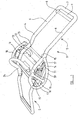
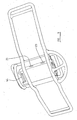
- the fitting 1 comprises two main parts 2,3 which are releasably connectable to one another.
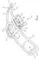
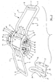
- Figure 3 illustrates the two main parts 2,3 in a condition in which they are released and separate from one another, whilst Figures 1 and 2 illustrate the two main parts 2,3 connected to one another.
- the first part 2 of the fitting comprises an elongate frame 4 which is bent from a length of rigid metal bar.
- the frame 4 defines a pair of rearwardly directed arms 5, each of which has a generally rectangular configuration and comprises a pair of rearwardly directed bar portions 6 which are interconnected by a terminal bar portion 7.
- a securing bar 8 Spaced slightly inwardly from each terminal bar portion 7, there is provided a securing bar 8 which extends between the two bar portions 6 of each arm 5.
- Each securing bar 8 is welded at each end to a respective bar portion 6.
- An elongate slot 9 is thus defined between the terminal bar portion 7 and the securing bar 8 of each arm 5.
- the central region of the frame 4 comprises a pair of central bar portions 10, each of which extends between a bar portion 6 of each arm 5.
- the frame 4 defining the two arms 5 is mounted centrally on a base plate 11 which is generally square or rectangular, but which has two opposed side regions bent inwardly to define a pair of inwardly directed flanges 12.
- Each flange 12 has a linear inner edge 13 and defines a respective elongate channel 14 between itself and the rear part of the base plate 11.
- the frame 4 is secured to the base plate 11 by four welds 15 in the regions of the ends of each inwardly directed flange 12.
- a smaller rectangular frame 16 is mounted to the base plate 11, and is oriented such that its longitudinal axis is generally perpendicular to the longitudinal axis of the frame 4 defining the pair of arms 5.
- the smaller frame 16 is mounted to the base plate 11 such that its two longitudinal bar portions 17 are each received within a respective channel 14 defined by the inwardly directed flanges 12.
- the smaller frame 16 is again welded to the base plate.
- the top region of the frame 16 is provided with a forwardly extending arcuate loop 18 which is welded to and extends between the two longitudinal bar portions 17 of the smaller frame 16.
- a similar loop 19, having a larger radius of curvature, is provided to extend downwardly from the frame 4 in the region of the base plate 11.
- the channel 20 comprises a front wall 21 and a pair of side walls 22.
- Each side wall 22 extends forwardly from the base plate 11 at a position spaced slightly inwards from the longitudinal edge 13 of a respective flange 12.
- Each side wall 22 is provided with two-spaced apart circular retaining apertures 23 ( Figure 3), the purpose of which will become clear hereinafter.
- the rectangular channel 20 encloses a locking mechanism which will be described in more detail hereinafter.
- the second part 3 of the fitting 1 comprises a hook 24 bent from a length of metal bar and secured, by a weld 25, to a rectangular flat plate 26. From each longitudinal edge 27 of the plate 26, extends a rearwardly directed side wall 28.
- the two side walls 28 are parallel with one another and are each provided with two spaced-spaced circular locking apertures 29.
- the apertures 29 formed through one side wall 28 are each aligned with a respective aperture formed through the opposite side wall 28.
- the apertures 29 provided through each side wall 28 are spaced from one another by a distance equal to the spacing between the apertures 23 provided to the side walls 22 extending forwardly from the base plate 11.
- the apertures 29 formed to the side walls 28 of the hook part 3 each have a slightly larger diameter than the apertures 22 carried by the first part 2.
- the edge of each aperture 29 defines a circular seat 29a, the purpose of which will become clear hereinafter.
- the channel 20 provided on the base plate 11 houses a locking mechanism.
- the locking mechanism will now be described, in more detail, with reference to Figures 5 to 8.
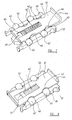
- the locking mechanism 30 takes the form of a generally rectangular cartridge 31 which is sized to be received within the channel 20 as illustrated generally in Figure 3.
- the cartridge 31 comprises a pair of substantially identical plastic mouldings 32, as illustrated in Figure 6, which define the cartridge 31 when positioned against one another as illustrated in Figure 5.
- Each cartridge moulding 32 has generally rectangular configuration and has a planar outer surface 33. From one end of each cartridge moulding 32 extend a pair of resiliently deformable fingers 34, each of which terminates with an outwardly directed projection 35.
- each cartridge moulding 32 is provided with a centrally located channel 36 of generally rectangular configuration. At one end of the channel 36, there is provided an upwardly extending projection 37. On either side of the channel 36, a pair of spaced apart rectangular recesses 38 are provided, each of which is open at its outermost end.
- the two cartridge mouldings 32 serve to house the operative parts of the mechanism 30 which include a generally rectangular metal locking element 41, a helically wound spring 42, and four locking members which, in the arrangement illustrated, take the form of balls 43.
- the locking element 41 is generally planar but is bent forwardly at one end to define a lip 44 which will serve as an actuating button.
- a rectangular slot 45 is formed through the locking element 41, the width of the slot being sized to receive the projection 37 as a sliding fit.
- the width of the locking element 41 is such that the locking element 41 as a whole can be mounted on the cartridge moulding 32 illustrated in Figure 7 so as to be a close sliding fit between the opposed shoulders 40, with the projection 37 received within the slot formed through the locking element 41.
- the spring 42 can be inserted through the slot 45 and into the channel 36 so as to engage the end of the channel 36 at one end, and the end of the slot 45 proximal to the actuating button 44 at the other end.
- Each recess 46 is generally arcuate and is configured to have a ramp surface 47 extending outwardly and away from the actuating button 44, to adjoin the longitudinal edge of the locking element 41.
- each ball 43 is sized to be received within a respective recess 38 provided along the side edges of the cartridge moulding 32. With the locking element 41 urged by the spring 42 towards the locking position as illustrated in Figure 7, each ball 43 bears against a longitudinal edge surface of the locking element 41.
- the other cartridge moulding 32 can then be positioned over the first cartridge moulding 32 such that the locking element 41, the spring 42 and the balls 43 are all located between the two cartridge mouldings 32 as illustrated in Figure 5.
- the locking mechanism 30 is assembled as shown in Figure 5
- the two cartridge mouldings 32 can be secured to one another by way of a peg or spigot carried by one moulding 32, which is received within a corresponding aperture provided on the other moulding.
- Each recess 38 of one cartridge moulding 32 is aligned with a respective recess 38 of the other cartridge moulding 32, hence defining a channel 48 in which each ball 43 is received.
- the balls 43 are not, in the configuration illustrated in Figure 5, held captive within the respective channels 48.
- the locking mechanism 30, when assembled as illustrated in Figure 5 is then inserted into the channel 20 provided on the first part 2 of the fitting 1.
- the cartridge 31 of the locking mechanism 30 is sized to be a close sliding fit within the channel 20 and so may be inserted into the channel from the top end, underneath the arcuate loop 18.
- the deformable fingers 34 of each cartridge moulding are depressed inwardly, and the balls 43 must be held in place to prevent them falling out of the open channels 48.
- the resilient fingers 34 are free to move outwardly under their resilience such that the projections 35 engage the lower end of the respective side walls 22, as illustrated in Figure 3.
- the actuating button is located generally behind the arcuate loop 18.
- the loop 18 thus serves as a guard arrangement extending around the actuating button 44 to prevent accidental actuation of the button 44.
- the transverse channels 48 of the locking mechanism 30 each become aligned with a respective aperture 23 formed through the side walls 22 projecting forwardly from the base plate 11.
- the apertures 22 are sized to prevent the balls 43 passing completely therethrough and hence serve to hold the balls 43 captive within their respective channels 48.
- the normal position of the operative parts of the mechanism 30 are generally as indicated in Figure 7, in which the spring 42 urges the locking element 41 into a locking position in which the upstanding projection 37 engages the end of the slot 45 remote from the actuating button 44.
- the balls 43 engage an outermost edge surface of the locking element 41 and are urged into the apertures 23 provided to the side walls 22 so as to project outwardly through the apertures 23.
- the actuating button 44 can be depressed, as indicated in Figure 9, and the balls 43 will each be allowed to move inwardly so as to no longer project through the apertures 23.
- the hook part 3 can be mounted on the main part 2 so that the plate 26 of the hook part bears against the front wall 21 of the channel 20.
- the two rearwardly extending side walls 28 of the hook part each bear against a respective side wall 23 extending forwardly from the base wall 11 and are received between the respective side walls 23 and the inner edge 13 of the adjacent flange portion 12.
- the apertures 29 formed through the side walls 28 of the hook part 3 each become aligned with a respective aperture 23 provided on the main part 2.
- the balls 43 are driven outwardly so that they project through the apertures 23 and into the apertures 29 formed on the hook part 3. This configuration is illustrated in Figures 1 and 2.
- each ball 43 is urged into engagement with a respective peripheral seat 29a defined by the apertures 29, and hence serve to lock the hook part 3 to the main part 2 in a substantially rigid manner as illustrated in Figures 1 and 2.
- the main part 2 of the fitting can be secured to a body harness such as, for example, a trapeze harness or wind-surfing harness such that the base plate 11 is located centrally, above the groin region of the harness.
- the two arms 5 extend outwardly around the waist region of the harness and the slots 9 each allow a respective webbing strap or the like to pass therethrough to provide secure connection of the main part 2 to the harness.
- the fitting 1 When mounted to the harness in this way, the fitting 1 presents the hook 24 in a convenient position to be clipped onto a tether line such as, for example, a trapeze wire.
- the four balls 43 are each driven outwardly into engagement with respective seats 29a defined by the apertures 29 on the hook part 3 and hence provide a secure connection between hook part 3 and the main part 2.
- the fitting 1 can be used to support the weight of a person wearing the harness, when hanging from a tether line clipped onto the hook 24.
- the person can simply depress the actuating button 44 as described above, which allows the four balls to move inwardly, hence moving out of engagement with the peripheral seats 29a defined by the aperture 29 as the hook part 3 is pulled away from the main part 2 under the force applied by the tether.
- the main part 2 of the fitting 1 and the hook part 3 hence become disconnected from one another allowing the person wearing the harness to become released from the tether line in an emergency.
- the balls 43 each present a rounded part for engagement with the peripheral seats 29a, the seats 29a are prevented from snagging on the balls as the hook part is pulled away from the main part 2.
- the seats 29a ride smoothly over the rounded surface of the balls 43, therefore ensuring that the balls 43 are properly urged inwardly.
- the locking members do not have to take the form of balls but instead could take the form of other convenient shapes such as, for example an elongate spigot having a rounded end surface, or a conical or frustoconical member presenting a tapered locking surface for engagement with the peripheral seats 29a.
- the apertures could be replaced with recesses defining the peripheral seats 29a, in which case the balls 43 would each be received in a respective said recess when engaging said peripheral seat, so as not to be visible when the hook-part 3 is connected to the main part 2 of the fitting 1.
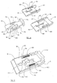
- FIG. 10 there is illustrated a fitting 51 in accordance with a second embodiment of the present invention.
- the fitting 51 again comprises two main parts 52, 53 which are releasably connectable to one another.
- Figure 12 illustrates the two main parts 52, 53 in a condition in which they are released and separate from one another, whilst Figures 10 and 11 illustrate the two main parts 2, 3 connected to one another.
- the first part 52 of the fitting again comprises an elongate frame 54 which defines a pair of outwardly-directed arms 55, each of which has a generally rectangular configuration and comprises a pair of outwardly-directed bar portions 56 which are interconnected by a respective terminal bar portion 57. Spaced slightly inwardly from each terminal bar portion 57, there is provided a securing bar 58 which extends between the two bar portions 56 of each arm 55. Each securing bar 58 is welded at each end to a respective bar portion 56. An elongate slot 59 is thus defined between the terminal bar portion 57 and the securing bar 58 of each arm 55.
- a generally rectangular base plate 60 is mounted centrally on the frame 54, and is secured thereto by four welds 61 in the comer regions of the base plate 60.
- a metal plate 62 which is bent into a generally U-shaped configuration is secured, again by welding, to the base plate 60 so as to define an elongate channel 63 of substantially rectangular cross-section, the channel 63 comprising a front wall 64 and a pair of opposed side walls 65.
- the front wall 64 of the channel 63 is provided with an elongate rectangular slot 66 therethrough which is aligned with a substantially identical slot 67 provided through the base plate 60.
- a pair of opposed and aligned circular apertures 68 are provided through the front wall 64, on opposite sides of the elongate rectangular slot 66.
- the rectangular channel 63 encloses a locking mechanism which will be described in more detail hereinafter.
- a plastic moulding 69 is releasably clipped to the front wall 64 of the channel 63.
- the plastic moulding 69 has a rounded bottom end 70 which is configured to close or plug the lower end of the channel 63.
- the upper end of the channel 63 is left open.
- An elongate slot 71 is provided through the plastic moulding 69, the elongate slot 71 being aligned with and slightly larger than the elongate slot 66 provided through the front wall 64 of the channel 63.
- a pair of circular apertures 72 are provided through the plastic moulding 69 which are aligned with the respective apertures 68 when the plastic moulding 69 is clipped to the front wall 64.
- the second part 53 of the fitting 51 comprises a hook 73 bent from a length of metal bar and secured, by a weld 74, to a rectangular flat plate 76.
- Three aligned circular locking apertures 77 are provided through the flat plate 76.
- the edge of each locking aperture 77 defines a circular locking seat 77a, the purpose of which is largely similar to that of the circular seats 29a of the previously-described embodiment, but which will be described in more detail hereinafter.
- a small plastic retaining clip 78 which extends from the region of the flat plate 76 to the end region of the hook 73.
- the retaining clip 78 serves to prevent accidental or inadvertent disengagement of the hook 73 from a tether line such as a trapeze wire. Also, as will become clear, if the second part 53 of the fitting 51 becomes released from the first part 52, then the retaining clip 58 ensures that the second part 53 remains attached to the end of the trapeze wire.
- the channel 63 provided on the base plate 60 has a locking mechanism.
- the locking mechanism will be now be described, in more detail, with reference to Figures 15 to 18.
- the locking mechanism 79 takes the form of a generally rectangular cartridge 80 which is sized to be received within the rectangular channel 63 as illustrated generally in Figures 10 to 12.
- the cartridge 80 comprises a pair of plastic mouldings 81,82 as illustrated in Figure 16, which together define the cartridge 80 when positioned against one another as illustrated in Figure 15.
- Each cartridge moulding 81,82 has a generally rectangular configuration and has a planar outer surface 83.
- Each cartridge moulding 81,82 is provided with an elongate slot 84 therethrough, and a pair of circular apertures 85 therethrough.
- Each cartridge moulding 81,82 is also provided with three recesses 86, 87 and 88 at positions adjacent the elongate slots 84.
- the recesses 86, 88 are provided at respective ends of the slot 84, and on the same side of the slot 84 as one another.
- the recess 87 is provided in the central region of the slot 84 and on the opposite side of the slot 84 to the recesses 86, 88.
- each cartridge moulding 81, 82 are configured so that when cartridge component 82 is overturned from its position illustrated in Figure 16 and is aligned with and positioned against the other cartridge component 81, then the two recesses 86 of each cartridge moulding will be aligned, as will the two recesses 87, and the two recesses 88 of each cartridge moulding 81, 82. It will therefore be appreciated that when the cartridge moulding 82 illustrated in Figure 16 is overturned and aligned with the other cartridge moulding 81, then the recesses 86, 87 and 88 define respective channels.
- each aperture 85 Extending away from each apertures 85, there are provided respective elongate recessed channels 89.
- the cartridge mouldings 81, 82 serve to house the operative parts of the locking mechanism 79, one of which is a locking element 90.
- the locking element 90 comprises a generally rectangular metal plate 91 which is provided with an extension 92 at one end which carries an actuating button 93.
- a pair of elongate slots 94 are provided through the rectangular plate 91 in the regions of respective longitudinal side edges of the plate 91.
- a more elaborate shaped slot 95 is provided through the central region of the rectangular plate 91.
- the central slot 95 defines three recesses 96, each of which has a generally "pear" shape so as to define respective first and second recess portions 97, 98.
- Each first recess portion 97 defines a straight edge 99
- each second recess portion 98 defines a ramp surface 100.
- each elongate slot 94 provided through the rectangular plate 91 is aligned over a respective recessed channel 89 of the cartridge moulding 81.
- a spring 101 is received within each elongate slot 94 so as to sit within a respective channel 89.
- each spring 101 serves to bias the locking element 90 towards the locking position illustrated in Figure 17.
- the locking element 90 in its locking position, is positioned such that the first recess portions 97 are each aligned with a respective recess 86, 87, 88 of the cartridge mouldings 81, 82.
- each recess 86, 87, 88 Received within each recess 86, 87, 88 is a respective locking member which, in the arrangement illustrated, takes the form of a ball 103.
- Each ball 103 is sized such that when the locking element 90 is positioned in its locking position shown in Figure 17, each ball 103 engages a respective straight edge 99 of the first recess portions 97, but extends at least partially across the elongate slots 84 provided through the two cartridge mouldings 81, 82.
- the other cartridge moulding 82 can be positioned over the first cartridge moulding 81 such that the locking element 90, the springs 101 and the balls 103 are all located between the two cartridge mouldings 81, 82 as illustrated in Figure 15.
- the locking mechanism 79 when assembled as illustrated in Figure 15 is then inserted into the channel 63 provided on the first part 52 of the fitting 51.
- the cartridge 80 of the locking mechanism 709 is sized to be a close sliding fit within the channel 63 and so may be inserted into the channel from the top end.
- the apertures 85 through the cartridge 80 become aligned with the apertures 68 through the front plate 64 of the channel 63 and with the aperture 72 provided through the plastic moulding 69.
- the retaining pins 102 can thus be inserted through all of the aligned apertures and into the slots 94 provided through the locking element 90, so as to engage the ends of the springs 101.
- the fitting 51 of the second embodiment is illustrated with the second part 53 of the fitting engaged by the locking mechanism 79 of the first fitting 52.
- the flat plate 76 is inserted through the slot 71 provided in the plastic moulding 69, and through the slot 66 provided in the front wall 64 of the channel 63.
- the flat plate 76 is thus received within the slots provided in the locking cartridge 80.
- Each locking aperture 77 is aligned with respective locking ball 103 such that each locking ball 103, being urged inwardly across the slot provided through the locking cartridge 80, engages a respective peripheral seat 77a, in order to releasably lock the second component 53 in position relative to the first component 51.
- the actuating button 93 can be held in a depressed condition whilst the plate 76 is re-introduced into the slots 84, whereafter the actuating button 93 can be released thus urging the locking balls 103 back into engagement with the peripheral seat 77a of each locking aperture 77.
- Figure 19 illustrates an alternative configuration for the second component part 53 of the embodiment of the fitting described above with reference to Figures 10 to 18.
- the alternative configuration for the second component part 53 illustrated in Figure 19 again comprises a substantially flat plate 76 having three locking apertures 77 provided therethrough, but the locking plate 76 is instead connected, by a weld 74, to a closed loop 104 defined by a length of bent metal bar.
- the closed loop 104 replaces the bent hook 73 of the arrangement disclosed above and provides an alternative arrangement for connection to the end of a tether line such as, for example, a trapeze wire.
Landscapes
- Chemical & Material Sciences (AREA)
- Engineering & Computer Science (AREA)
- Combustion & Propulsion (AREA)
- Mechanical Engineering (AREA)
- Ocean & Marine Engineering (AREA)
- Quick-Acting Or Multi-Walled Pipe Joints (AREA)
- Insulated Conductors (AREA)
- Installation Of Indoor Wiring (AREA)
- Adornments (AREA)
Applications Claiming Priority (4)
| Application Number | Priority Date | Filing Date | Title |
|---|---|---|---|
| GB0304041 | 2003-02-21 | ||
| GBGB0304041.7A GB0304041D0 (en) | 2003-02-21 | 2003-02-21 | Improvements in or relating to a fitting for a harness |
| GB0308440A GB2398602B (en) | 2003-02-21 | 2003-04-11 | Improvements in or relating to a fitting for a harness |
| GB0308440 | 2003-04-11 |
Publications (2)
| Publication Number | Publication Date |
|---|---|
| EP1449761A1 true EP1449761A1 (fr) | 2004-08-25 |
| EP1449761B1 EP1449761B1 (fr) | 2006-12-20 |
Family
ID=32737558
Family Applications (1)
| Application Number | Title | Priority Date | Filing Date |
|---|---|---|---|
| EP04003825A Expired - Lifetime EP1449761B1 (fr) | 2003-02-21 | 2004-02-19 | Améliorations dans ou concernant l'attache d'un harnais |
Country Status (5)
| Country | Link |
|---|---|
| US (1) | US7346966B2 (fr) |
| EP (1) | EP1449761B1 (fr) |
| AT (1) | ATE348751T1 (fr) |
| AU (1) | AU2004200672B2 (fr) |
| DE (1) | DE602004003730D1 (fr) |
Families Citing this family (5)
| Publication number | Priority date | Publication date | Assignee | Title |
|---|---|---|---|---|
| ITFI20050145A1 (it) * | 2005-06-29 | 2006-12-30 | Nardi Dei Gherardo Flaccomio | Dispositivo di fissaggio per kite surfing per l'aggancio e scangio dell'ala al corpo del surfista |
| US20120304942A1 (en) * | 2011-06-02 | 2012-12-06 | Ronald Louro | Apparatus for Coupling a Pet Leash and a Pet Collar |
| US10398132B2 (en) * | 2011-06-02 | 2019-09-03 | Ronald Louro | Apparatus for coupling a pet leash and pet collar |
| US9468195B2 (en) | 2012-11-01 | 2016-10-18 | Thundershirt, Llc | Convertible leash and harness system and method |
| USD757376S1 (en) | 2014-11-03 | 2016-05-24 | Thundershirt, Llc | Harness and leash adapter |
Citations (5)
| Publication number | Priority date | Publication date | Assignee | Title |
|---|---|---|---|---|
| FR2373295A2 (fr) * | 1976-12-13 | 1978-07-07 | Carn Patrick | Perfectionnements apportes aux dispositifs du type harnais, en particulier dans la pratique de la navigation |
| US4452161A (en) * | 1980-08-11 | 1984-06-05 | Mccoy Donald G | Hook for attaching rider to board sailer |
| US4754532A (en) * | 1987-02-24 | 1988-07-05 | Thomson Richard E | Adjustable quick release magnetic holding assembly |
| FR2744419A1 (fr) * | 1996-02-06 | 1997-08-08 | Vessieres Jean Marc Didier | Mecanisme d'accrochage a declenchement pour harnais |
| US6293215B1 (en) * | 1997-07-04 | 2001-09-25 | Neil Pryde Limited | Sailing harness |
Family Cites Families (18)
| Publication number | Priority date | Publication date | Assignee | Title |
|---|---|---|---|---|
| US2693980A (en) * | 1951-09-15 | 1954-11-09 | Jr William A Heidman | Coupling unit |
| US3188707A (en) * | 1963-06-24 | 1965-06-15 | Benjamin F Schmidt | Remotely releasable safety belt buckle |
| US3473201A (en) * | 1967-01-03 | 1969-10-21 | Robbins Seat Belt Co | Seat belt buckle |
| GB1542205A (en) * | 1976-03-23 | 1979-03-14 | Carn P | Harness |
| US4140205A (en) * | 1978-03-15 | 1979-02-20 | Matson Theodore C | Safety release boat trapeze hook |
| IT1117615B (it) | 1979-02-12 | 1986-02-17 | Sabelt Spa | Perfezionamento alle fibbie per cinture di sicurezza e relativa fibbia perfezionata |
| US4184783A (en) * | 1978-04-26 | 1980-01-22 | General Electric Company | Readily disengagable clevis |
| DE2930598A1 (de) | 1979-07-27 | 1981-02-05 | Wunder Kg Heinrich | Sicherheitsschnalle fuer trapezgurte, insbesondere zur benutzung bei segelbrettern |
| WO1982000448A1 (fr) | 1980-08-11 | 1982-02-18 | D Mccoy | Crochet permettant d'attacher un utilisateur a une planche a voile |
| US4378614A (en) * | 1980-09-08 | 1983-04-05 | Mckenney John | Automatic-release hook for sailboard harness |
| US4540218A (en) * | 1983-06-06 | 1985-09-10 | Allied Corporation | Safety belt system for childs chair |
| GB2170260B (en) | 1984-12-10 | 1988-03-09 | Wei Cheong Metalware Factory L | A fastener |
| IT218275Z2 (it) | 1989-08-10 | 1992-04-14 | Vittorio Romano Barbuti | Dispositivo di sganciamento rapido per cinture di sicurezza per automobili |
| US5924522A (en) * | 1997-05-16 | 1999-07-20 | Ostrobrod; Meyer | Cable grab |
| GB2325957A (en) | 1997-06-06 | 1998-12-09 | Europ Component Co Ltd | Seat belt buckle |
| US6343824B1 (en) | 1998-02-11 | 2002-02-05 | Peter Stuart Foy | Apparatus for suspending a load |
| TWI229628B (en) * | 2001-07-31 | 2005-03-21 | Mau-Tang Liou | An assembling and fixing device of a knocking tool |
| US6640397B1 (en) * | 2002-06-20 | 2003-11-04 | Dale Gipson | Quick release harness device |
-
2004
- 2004-02-19 EP EP04003825A patent/EP1449761B1/fr not_active Expired - Lifetime
- 2004-02-19 AT AT04003825T patent/ATE348751T1/de not_active IP Right Cessation
- 2004-02-19 DE DE602004003730T patent/DE602004003730D1/de not_active Expired - Lifetime
- 2004-02-20 AU AU2004200672A patent/AU2004200672B2/en not_active Ceased
- 2004-02-20 US US10/784,137 patent/US7346966B2/en not_active Expired - Fee Related
Patent Citations (5)
| Publication number | Priority date | Publication date | Assignee | Title |
|---|---|---|---|---|
| FR2373295A2 (fr) * | 1976-12-13 | 1978-07-07 | Carn Patrick | Perfectionnements apportes aux dispositifs du type harnais, en particulier dans la pratique de la navigation |
| US4452161A (en) * | 1980-08-11 | 1984-06-05 | Mccoy Donald G | Hook for attaching rider to board sailer |
| US4754532A (en) * | 1987-02-24 | 1988-07-05 | Thomson Richard E | Adjustable quick release magnetic holding assembly |
| FR2744419A1 (fr) * | 1996-02-06 | 1997-08-08 | Vessieres Jean Marc Didier | Mecanisme d'accrochage a declenchement pour harnais |
| US6293215B1 (en) * | 1997-07-04 | 2001-09-25 | Neil Pryde Limited | Sailing harness |
Also Published As
| Publication number | Publication date |
|---|---|
| US20050115519A1 (en) | 2005-06-02 |
| US7346966B2 (en) | 2008-03-25 |
| EP1449761B1 (fr) | 2006-12-20 |
| ATE348751T1 (de) | 2007-01-15 |
| DE602004003730D1 (de) | 2007-02-01 |
| AU2004200672A1 (en) | 2004-09-09 |
| AU2004200672A2 (en) | 2004-09-09 |
| AU2004200672B2 (en) | 2010-08-19 |
Similar Documents
| Publication | Publication Date | Title |
|---|---|---|
| US4452161A (en) | Hook for attaching rider to board sailer | |
| US5661877A (en) | Belt or webbing buckle having plural independently operable securement and release mechanisms | |
| US7107926B2 (en) | Bimini top main bow connector | |
| US5334099A (en) | Restraining bar assembly for a swing | |
| US10407131B1 (en) | Platform and system for boat | |
| US7162968B2 (en) | Bimini top hook | |
| EP4071045A1 (fr) | Dispositif utilisé pour connecter et libérer une connexion entre deux éléments | |
| US6463640B1 (en) | Strap connecting buckle | |
| AU658039B2 (en) | Adjustable rope lock | |
| US4140205A (en) | Safety release boat trapeze hook | |
| US4993123A (en) | Adjustable nautical rope lock | |
| US7346966B2 (en) | Fitting for a harness | |
| WO2008087589A1 (fr) | Palme de natation et chaussure pour celle-ci | |
| US5388661A (en) | Safety strap for securing a body harness to a scaffolding structure | |
| GB2398602A (en) | Releasable fitting for a sailboat harness | |
| US9211938B1 (en) | Dual rod mooring pendant apparatus | |
| US3798716A (en) | Snap fastening device | |
| US7762497B2 (en) | Automatic kitesurf release system | |
| US12434796B2 (en) | Board holder for storing a marine board | |
| EP0057221A1 (fr) | Crochet permettant d'attacher un utilisateur a une planche a voile | |
| US5738033A (en) | Bumper and sling arrangement to assist boat docking | |
| US7267064B2 (en) | Harness suitable for use on watercraft | |
| US7464656B2 (en) | Attachment device releasable under a load for a trapeze harness used in sailing | |
| US20040040486A1 (en) | Mooring assembly | |
| GB2326905A (en) | Ladder e.g. for climbing masts |
Legal Events
| Date | Code | Title | Description |
|---|---|---|---|
| PUAI | Public reference made under article 153(3) epc to a published international application that has entered the european phase |
Free format text: ORIGINAL CODE: 0009012 |
|
| AK | Designated contracting states |
Kind code of ref document: A1 Designated state(s): AT BE BG CH CY CZ DE DK EE ES FI FR GB GR HU IE IT LI LU MC NL PT RO SE SI SK TR |
|
| AX | Request for extension of the european patent |
Extension state: AL LT LV MK |
|
| 17P | Request for examination filed |
Effective date: 20050223 |
|
| AKX | Designation fees paid |
Designated state(s): AT BE BG CH CY CZ DE DK EE ES FI FR GB GR HU IE IT LI LU MC NL PT RO SE SI SK TR |
|
| GRAP | Despatch of communication of intention to grant a patent |
Free format text: ORIGINAL CODE: EPIDOSNIGR1 |
|
| GRAS | Grant fee paid |
Free format text: ORIGINAL CODE: EPIDOSNIGR3 |
|
| GRAA | (expected) grant |
Free format text: ORIGINAL CODE: 0009210 |
|
| AK | Designated contracting states |
Kind code of ref document: B1 Designated state(s): AT BE BG CH CY CZ DE DK EE ES FI FR GB GR HU IE IT LI LU MC NL PT RO SE SI SK TR |
|
| PG25 | Lapsed in a contracting state [announced via postgrant information from national office to epo] |
Ref country code: CH Free format text: LAPSE BECAUSE OF FAILURE TO SUBMIT A TRANSLATION OF THE DESCRIPTION OR TO PAY THE FEE WITHIN THE PRESCRIBED TIME-LIMIT Effective date: 20061220 Ref country code: CZ Free format text: LAPSE BECAUSE OF FAILURE TO SUBMIT A TRANSLATION OF THE DESCRIPTION OR TO PAY THE FEE WITHIN THE PRESCRIBED TIME-LIMIT Effective date: 20061220 Ref country code: SI Free format text: LAPSE BECAUSE OF FAILURE TO SUBMIT A TRANSLATION OF THE DESCRIPTION OR TO PAY THE FEE WITHIN THE PRESCRIBED TIME-LIMIT Effective date: 20061220 Ref country code: FI Free format text: LAPSE BECAUSE OF FAILURE TO SUBMIT A TRANSLATION OF THE DESCRIPTION OR TO PAY THE FEE WITHIN THE PRESCRIBED TIME-LIMIT Effective date: 20061220 Ref country code: DK Free format text: LAPSE BECAUSE OF FAILURE TO SUBMIT A TRANSLATION OF THE DESCRIPTION OR TO PAY THE FEE WITHIN THE PRESCRIBED TIME-LIMIT Effective date: 20061220 Ref country code: RO Free format text: LAPSE BECAUSE OF FAILURE TO SUBMIT A TRANSLATION OF THE DESCRIPTION OR TO PAY THE FEE WITHIN THE PRESCRIBED TIME-LIMIT Effective date: 20061220 Ref country code: AT Free format text: LAPSE BECAUSE OF FAILURE TO SUBMIT A TRANSLATION OF THE DESCRIPTION OR TO PAY THE FEE WITHIN THE PRESCRIBED TIME-LIMIT Effective date: 20061220 Ref country code: NL Free format text: LAPSE BECAUSE OF FAILURE TO SUBMIT A TRANSLATION OF THE DESCRIPTION OR TO PAY THE FEE WITHIN THE PRESCRIBED TIME-LIMIT Effective date: 20061220 Ref country code: LI Free format text: LAPSE BECAUSE OF FAILURE TO SUBMIT A TRANSLATION OF THE DESCRIPTION OR TO PAY THE FEE WITHIN THE PRESCRIBED TIME-LIMIT Effective date: 20061220 Ref country code: SK Free format text: LAPSE BECAUSE OF FAILURE TO SUBMIT A TRANSLATION OF THE DESCRIPTION OR TO PAY THE FEE WITHIN THE PRESCRIBED TIME-LIMIT Effective date: 20061220 Ref country code: BE Free format text: LAPSE BECAUSE OF FAILURE TO SUBMIT A TRANSLATION OF THE DESCRIPTION OR TO PAY THE FEE WITHIN THE PRESCRIBED TIME-LIMIT Effective date: 20061220 |
|
| REG | Reference to a national code |
Ref country code: GB Ref legal event code: FG4D |
|
| REG | Reference to a national code |
Ref country code: CH Ref legal event code: EP |
|
| REF | Corresponds to: |
Ref document number: 602004003730 Country of ref document: DE Date of ref document: 20070201 Kind code of ref document: P |
|
| REG | Reference to a national code |
Ref country code: IE Ref legal event code: FG4D |
|
| PG25 | Lapsed in a contracting state [announced via postgrant information from national office to epo] |
Ref country code: MC Free format text: LAPSE BECAUSE OF NON-PAYMENT OF DUE FEES Effective date: 20070228 |
|
| PG25 | Lapsed in a contracting state [announced via postgrant information from national office to epo] |
Ref country code: BG Free format text: LAPSE BECAUSE OF FAILURE TO SUBMIT A TRANSLATION OF THE DESCRIPTION OR TO PAY THE FEE WITHIN THE PRESCRIBED TIME-LIMIT Effective date: 20070320 Ref country code: SE Free format text: LAPSE BECAUSE OF FAILURE TO SUBMIT A TRANSLATION OF THE DESCRIPTION OR TO PAY THE FEE WITHIN THE PRESCRIBED TIME-LIMIT Effective date: 20070320 |
|
| PG25 | Lapsed in a contracting state [announced via postgrant information from national office to epo] |
Ref country code: DE Free format text: LAPSE BECAUSE OF FAILURE TO SUBMIT A TRANSLATION OF THE DESCRIPTION OR TO PAY THE FEE WITHIN THE PRESCRIBED TIME-LIMIT Effective date: 20070321 |
|
| PG25 | Lapsed in a contracting state [announced via postgrant information from national office to epo] |
Ref country code: ES Free format text: LAPSE BECAUSE OF FAILURE TO SUBMIT A TRANSLATION OF THE DESCRIPTION OR TO PAY THE FEE WITHIN THE PRESCRIBED TIME-LIMIT Effective date: 20070331 |
|
| PG25 | Lapsed in a contracting state [announced via postgrant information from national office to epo] |
Ref country code: PT Free format text: LAPSE BECAUSE OF FAILURE TO SUBMIT A TRANSLATION OF THE DESCRIPTION OR TO PAY THE FEE WITHIN THE PRESCRIBED TIME-LIMIT Effective date: 20070424 |
|
| NLV1 | Nl: lapsed or annulled due to failure to fulfill the requirements of art. 29p and 29m of the patents act | ||
| REG | Reference to a national code |
Ref country code: CH Ref legal event code: PL |
|
| ET | Fr: translation filed | ||
| PLBE | No opposition filed within time limit |
Free format text: ORIGINAL CODE: 0009261 |
|
| STAA | Information on the status of an ep patent application or granted ep patent |
Free format text: STATUS: NO OPPOSITION FILED WITHIN TIME LIMIT |
|
| 26N | No opposition filed |
Effective date: 20070921 |
|
| PG25 | Lapsed in a contracting state [announced via postgrant information from national office to epo] |
Ref country code: IE Free format text: LAPSE BECAUSE OF NON-PAYMENT OF DUE FEES Effective date: 20070219 |
|
| PG25 | Lapsed in a contracting state [announced via postgrant information from national office to epo] |
Ref country code: GR Free format text: LAPSE BECAUSE OF FAILURE TO SUBMIT A TRANSLATION OF THE DESCRIPTION OR TO PAY THE FEE WITHIN THE PRESCRIBED TIME-LIMIT Effective date: 20070321 |
|
| PG25 | Lapsed in a contracting state [announced via postgrant information from national office to epo] |
Ref country code: EE Free format text: LAPSE BECAUSE OF FAILURE TO SUBMIT A TRANSLATION OF THE DESCRIPTION OR TO PAY THE FEE WITHIN THE PRESCRIBED TIME-LIMIT Effective date: 20061220 |
|
| PG25 | Lapsed in a contracting state [announced via postgrant information from national office to epo] |
Ref country code: LU Free format text: LAPSE BECAUSE OF NON-PAYMENT OF DUE FEES Effective date: 20070219 Ref country code: CY Free format text: LAPSE BECAUSE OF FAILURE TO SUBMIT A TRANSLATION OF THE DESCRIPTION OR TO PAY THE FEE WITHIN THE PRESCRIBED TIME-LIMIT Effective date: 20061220 |
|
| PG25 | Lapsed in a contracting state [announced via postgrant information from national office to epo] |
Ref country code: HU Free format text: LAPSE BECAUSE OF FAILURE TO SUBMIT A TRANSLATION OF THE DESCRIPTION OR TO PAY THE FEE WITHIN THE PRESCRIBED TIME-LIMIT Effective date: 20070621 Ref country code: TR Free format text: LAPSE BECAUSE OF FAILURE TO SUBMIT A TRANSLATION OF THE DESCRIPTION OR TO PAY THE FEE WITHIN THE PRESCRIBED TIME-LIMIT Effective date: 20061220 |
|
| PGFP | Annual fee paid to national office [announced via postgrant information from national office to epo] |
Ref country code: GB Payment date: 20110316 Year of fee payment: 8 |
|
| PGFP | Annual fee paid to national office [announced via postgrant information from national office to epo] |
Ref country code: FR Payment date: 20120221 Year of fee payment: 9 |
|
| PGFP | Annual fee paid to national office [announced via postgrant information from national office to epo] |
Ref country code: IT Payment date: 20120213 Year of fee payment: 9 |
|
| GBPC | Gb: european patent ceased through non-payment of renewal fee |
Effective date: 20120219 |
|
| PG25 | Lapsed in a contracting state [announced via postgrant information from national office to epo] |
Ref country code: GB Free format text: LAPSE BECAUSE OF NON-PAYMENT OF DUE FEES Effective date: 20120219 |
|
| REG | Reference to a national code |
Ref country code: FR Ref legal event code: ST Effective date: 20131031 |
|
| PG25 | Lapsed in a contracting state [announced via postgrant information from national office to epo] |
Ref country code: IT Free format text: LAPSE BECAUSE OF NON-PAYMENT OF DUE FEES Effective date: 20130219 |
|
| PG25 | Lapsed in a contracting state [announced via postgrant information from national office to epo] |
Ref country code: FR Free format text: LAPSE BECAUSE OF NON-PAYMENT OF DUE FEES Effective date: 20130228 |