EP1450006B1 - Aube de compresseur pour un moteur d'avion - Google Patents
Aube de compresseur pour un moteur d'avion Download PDFInfo
- Publication number
- EP1450006B1 EP1450006B1 EP04090042A EP04090042A EP1450006B1 EP 1450006 B1 EP1450006 B1 EP 1450006B1 EP 04090042 A EP04090042 A EP 04090042A EP 04090042 A EP04090042 A EP 04090042A EP 1450006 B1 EP1450006 B1 EP 1450006B1
- Authority
- EP
- European Patent Office
- Prior art keywords
- leading
- blade
- compressor blade
- accordance
- leading edge
- Prior art date
- Legal status (The legal status is an assumption and is not a legal conclusion. Google has not performed a legal analysis and makes no representation as to the accuracy of the status listed.)
- Expired - Lifetime
Links
- 239000000463 material Substances 0.000 claims description 24
- 239000000835 fiber Substances 0.000 claims description 19
- 229910052751 metal Inorganic materials 0.000 claims description 12
- 239000002184 metal Substances 0.000 claims description 12
- 239000007787 solid Substances 0.000 claims description 6
- 229910000831 Steel Inorganic materials 0.000 claims description 3
- 239000010959 steel Substances 0.000 claims description 3
- 150000001875 compounds Chemical class 0.000 claims 4
- 229910001092 metal group alloy Inorganic materials 0.000 claims 1
- 150000002739 metals Chemical class 0.000 claims 1
- 238000000465 moulding Methods 0.000 description 34
- 239000002131 composite material Substances 0.000 description 17
- 230000003628 erosive effect Effects 0.000 description 10
- RTAQQCXQSZGOHL-UHFFFAOYSA-N Titanium Chemical compound [Ti] RTAQQCXQSZGOHL-UHFFFAOYSA-N 0.000 description 5
- 238000005260 corrosion Methods 0.000 description 4
- 230000007797 corrosion Effects 0.000 description 4
- 239000010936 titanium Substances 0.000 description 4
- 229910052719 titanium Inorganic materials 0.000 description 4
- 238000013016 damping Methods 0.000 description 3
- 229920002430 Fibre-reinforced plastic Polymers 0.000 description 2
- 229920000914 Metallic fiber Polymers 0.000 description 2
- PXHVJJICTQNCMI-UHFFFAOYSA-N Nickel Chemical compound [Ni] PXHVJJICTQNCMI-UHFFFAOYSA-N 0.000 description 2
- 238000005336 cracking Methods 0.000 description 2
- 230000001419 dependent effect Effects 0.000 description 2
- 238000011161 development Methods 0.000 description 2
- 230000018109 developmental process Effects 0.000 description 2
- 230000000694 effects Effects 0.000 description 2
- 239000011151 fibre-reinforced plastic Substances 0.000 description 2
- 239000002657 fibrous material Substances 0.000 description 2
- 238000004519 manufacturing process Methods 0.000 description 2
- 238000003466 welding Methods 0.000 description 2
- 229920000049 Carbon (fiber) Polymers 0.000 description 1
- 238000004873 anchoring Methods 0.000 description 1
- 238000005452 bending Methods 0.000 description 1
- 239000011230 binding agent Substances 0.000 description 1
- 239000004917 carbon fiber Substances 0.000 description 1
- 239000011248 coating agent Substances 0.000 description 1
- 238000000576 coating method Methods 0.000 description 1
- 238000009792 diffusion process Methods 0.000 description 1
- 239000003822 epoxy resin Substances 0.000 description 1
- 238000005530 etching Methods 0.000 description 1
- 239000004744 fabric Substances 0.000 description 1
- 239000000446 fuel Substances 0.000 description 1
- 238000007689 inspection Methods 0.000 description 1
- 239000011159 matrix material Substances 0.000 description 1
- VNWKTOKETHGBQD-UHFFFAOYSA-N methane Chemical compound C VNWKTOKETHGBQD-UHFFFAOYSA-N 0.000 description 1
- 229910052759 nickel Inorganic materials 0.000 description 1
- 239000002245 particle Substances 0.000 description 1
- 229920000647 polyepoxide Polymers 0.000 description 1
- 230000002250 progressing effect Effects 0.000 description 1
- 229920005989 resin Polymers 0.000 description 1
- 239000011347 resin Substances 0.000 description 1
- 238000007788 roughening Methods 0.000 description 1
- 239000004576 sand Substances 0.000 description 1
- 238000004513 sizing Methods 0.000 description 1
- 230000007704 transition Effects 0.000 description 1
- 230000003313 weakening effect Effects 0.000 description 1
- 238000009941 weaving Methods 0.000 description 1
Images
Classifications
-
- B—PERFORMING OPERATIONS; TRANSPORTING
- B64—AIRCRAFT; AVIATION; COSMONAUTICS
- B64C—AEROPLANES; HELICOPTERS
- B64C11/00—Propellers, e.g. of ducted type; Features common to propellers and rotors for rotorcraft
- B64C11/16—Blades
- B64C11/20—Constructional features
- B64C11/205—Constructional features for protecting blades, e.g. coating
-
- B—PERFORMING OPERATIONS; TRANSPORTING
- B23—MACHINE TOOLS; METAL-WORKING NOT OTHERWISE PROVIDED FOR
- B23P—METAL-WORKING NOT OTHERWISE PROVIDED FOR; COMBINED OPERATIONS; UNIVERSAL MACHINE TOOLS
- B23P15/00—Making specific metal objects by operations not covered by a single other subclass or a group in this subclass
- B23P15/04—Making specific metal objects by operations not covered by a single other subclass or a group in this subclass turbine or like blades from several pieces
-
- F—MECHANICAL ENGINEERING; LIGHTING; HEATING; WEAPONS; BLASTING
- F01—MACHINES OR ENGINES IN GENERAL; ENGINE PLANTS IN GENERAL; STEAM ENGINES
- F01D—NON-POSITIVE DISPLACEMENT MACHINES OR ENGINES, e.g. STEAM TURBINES
- F01D5/00—Blades; Blade-carrying members; Heating, heat-insulating, cooling or antivibration means on the blades or the members
- F01D5/12—Blades
- F01D5/14—Form or construction
- F01D5/147—Construction, i.e. structural features, e.g. of weight-saving hollow blades
-
- F—MECHANICAL ENGINEERING; LIGHTING; HEATING; WEAPONS; BLASTING
- F01—MACHINES OR ENGINES IN GENERAL; ENGINE PLANTS IN GENERAL; STEAM ENGINES
- F01D—NON-POSITIVE DISPLACEMENT MACHINES OR ENGINES, e.g. STEAM TURBINES
- F01D5/00—Blades; Blade-carrying members; Heating, heat-insulating, cooling or antivibration means on the blades or the members
- F01D5/12—Blades
- F01D5/28—Selecting particular materials; Particular measures relating thereto; Measures against erosion or corrosion
- F01D5/282—Selecting composite materials, e.g. blades with reinforcing filaments
-
- F—MECHANICAL ENGINEERING; LIGHTING; HEATING; WEAPONS; BLASTING
- F04—POSITIVE - DISPLACEMENT MACHINES FOR LIQUIDS; PUMPS FOR LIQUIDS OR ELASTIC FLUIDS
- F04D—NON-POSITIVE-DISPLACEMENT PUMPS
- F04D29/00—Details, component parts, or accessories
- F04D29/02—Selection of particular materials
- F04D29/023—Selection of particular materials especially adapted for elastic fluid pumps
-
- F—MECHANICAL ENGINEERING; LIGHTING; HEATING; WEAPONS; BLASTING
- F04—POSITIVE - DISPLACEMENT MACHINES FOR LIQUIDS; PUMPS FOR LIQUIDS OR ELASTIC FLUIDS
- F04D—NON-POSITIVE-DISPLACEMENT PUMPS
- F04D29/00—Details, component parts, or accessories
- F04D29/26—Rotors specially for elastic fluids
- F04D29/32—Rotors specially for elastic fluids for axial flow pumps
- F04D29/321—Rotors specially for elastic fluids for axial flow pumps for axial flow compressors
- F04D29/324—Blades
-
- F—MECHANICAL ENGINEERING; LIGHTING; HEATING; WEAPONS; BLASTING
- F05—INDEXING SCHEMES RELATING TO ENGINES OR PUMPS IN VARIOUS SUBCLASSES OF CLASSES F01-F04
- F05D—INDEXING SCHEME FOR ASPECTS RELATING TO NON-POSITIVE-DISPLACEMENT MACHINES OR ENGINES, GAS-TURBINES OR JET-PROPULSION PLANTS
- F05D2240/00—Components
- F05D2240/20—Rotors
- F05D2240/30—Characteristics of rotor blades, i.e. of any element transforming dynamic fluid energy to or from rotational energy and being attached to a rotor
- F05D2240/303—Characteristics of rotor blades, i.e. of any element transforming dynamic fluid energy to or from rotational energy and being attached to a rotor related to the leading edge of a rotor blade
-
- F—MECHANICAL ENGINEERING; LIGHTING; HEATING; WEAPONS; BLASTING
- F05—INDEXING SCHEMES RELATING TO ENGINES OR PUMPS IN VARIOUS SUBCLASSES OF CLASSES F01-F04
- F05D—INDEXING SCHEME FOR ASPECTS RELATING TO NON-POSITIVE-DISPLACEMENT MACHINES OR ENGINES, GAS-TURBINES OR JET-PROPULSION PLANTS
- F05D2300/00—Materials; Properties thereof
- F05D2300/10—Metals, alloys or intermetallic compounds
- F05D2300/13—Refractory metals, i.e. Ti, V, Cr, Zr, Nb, Mo, Hf, Ta, W
- F05D2300/133—Titanium
-
- F—MECHANICAL ENGINEERING; LIGHTING; HEATING; WEAPONS; BLASTING
- F05—INDEXING SCHEMES RELATING TO ENGINES OR PUMPS IN VARIOUS SUBCLASSES OF CLASSES F01-F04
- F05D—INDEXING SCHEME FOR ASPECTS RELATING TO NON-POSITIVE-DISPLACEMENT MACHINES OR ENGINES, GAS-TURBINES OR JET-PROPULSION PLANTS
- F05D2300/00—Materials; Properties thereof
- F05D2300/10—Metals, alloys or intermetallic compounds
- F05D2300/16—Other metals not provided for in groups F05D2300/11 - F05D2300/15
-
- F—MECHANICAL ENGINEERING; LIGHTING; HEATING; WEAPONS; BLASTING
- F05—INDEXING SCHEMES RELATING TO ENGINES OR PUMPS IN VARIOUS SUBCLASSES OF CLASSES F01-F04
- F05D—INDEXING SCHEME FOR ASPECTS RELATING TO NON-POSITIVE-DISPLACEMENT MACHINES OR ENGINES, GAS-TURBINES OR JET-PROPULSION PLANTS
- F05D2300/00—Materials; Properties thereof
- F05D2300/10—Metals, alloys or intermetallic compounds
- F05D2300/17—Alloys
- F05D2300/171—Steel alloys
-
- F—MECHANICAL ENGINEERING; LIGHTING; HEATING; WEAPONS; BLASTING
- F05—INDEXING SCHEMES RELATING TO ENGINES OR PUMPS IN VARIOUS SUBCLASSES OF CLASSES F01-F04
- F05D—INDEXING SCHEME FOR ASPECTS RELATING TO NON-POSITIVE-DISPLACEMENT MACHINES OR ENGINES, GAS-TURBINES OR JET-PROPULSION PLANTS
- F05D2300/00—Materials; Properties thereof
- F05D2300/60—Properties or characteristics given to material by treatment or manufacturing
- F05D2300/614—Fibres or filaments
-
- Y—GENERAL TAGGING OF NEW TECHNOLOGICAL DEVELOPMENTS; GENERAL TAGGING OF CROSS-SECTIONAL TECHNOLOGIES SPANNING OVER SEVERAL SECTIONS OF THE IPC; TECHNICAL SUBJECTS COVERED BY FORMER USPC CROSS-REFERENCE ART COLLECTIONS [XRACs] AND DIGESTS
- Y02—TECHNOLOGIES OR APPLICATIONS FOR MITIGATION OR ADAPTATION AGAINST CLIMATE CHANGE
- Y02T—CLIMATE CHANGE MITIGATION TECHNOLOGIES RELATED TO TRANSPORTATION
- Y02T50/00—Aeronautics or air transport
- Y02T50/60—Efficient propulsion technologies, e.g. for aircraft
Definitions
- the invention relates to a compressor blade for an aircraft engine, the blade of which comprises a blade core made of a fiber composite material and a multi-part metallic casing.
- the blades of turbomachines and in particular of aircraft engines are exposed to centrifugal forces, gas pressure and excited by the flowing medium vibrations of the airfoil, but also by erosion due sucked foreign particles or corrosion significant loads.
- the compressor blades of aircraft engines can additionally and to a considerable extent be burdened by the impact of a bird on the fan blades caused bird strike.
- the corresponding highest safety requirements are countered by the desire to reduce the manufacturing costs and to reduce the specific fuel consumption by reducing the weight of the blades and thus also the anti-burst elements of the engine.
- This design for rotating blades can be used in the same way for stator blades.
- hollow-shaped blades In order to reduce weight, hollow-shaped blades are known, but their production is associated with extremely high costs and their use is therefore economically justifiable only for large engines. Since the use of hollow-design engine blades for low-thrust engines is ineffective in terms of the ratio between the weight savings that can be achieved and the cost required therefor is, the correspondingly smaller blades of such engines are still made of solid titanium. Although they withstand the above-mentioned stresses, they are nevertheless susceptible to the vibrations caused by the flow and are also heavy and expensive.
- blades made of fiber composites have been developed, which, although having significant weight advantages over a conventional blade massively produced from a suitable metal and also have a specific strength and high internal damping to prevent vibrations, but the strict resistance criteria with respect to erosion or do not suffice a bird strike acting on the surface or leading edge of the airfoil.
- US-A-4,006,999 discloses a compressor blade having a vane core made of a fiber composite material and a metal leading edge fitting attached to the leading edge and held to the fiber composite.
- the cross-sectionally asymmetrical that is, on the pressure side longer than on the suction side formed leading edge molding, has a groove, into which protrudes the fiber composite material.
- a hollow blade described in GB-A-1 276 485, which may also be filled with a filling material, comprises a two-part covering consisting of a leading edge molding with integrally formed cover sheet and a cover sheet welded directly to the leading edge molding on the pressure side.
- US Pat. No. 5,655,883 describes a compressor blade consisting of a carbon fiber composite in an epoxy resin matrix and a titanium cover, the titanium part of which comprises the Covering the suction side and the leading edge and trailing edge and blade tip area.
- a blade for a turbomachine which comprises a laminate of fiber-reinforced plastic, the surface of which is partially or fully covered with a layer of metallic fibers or threads, with the adjacent fiber-reinforced plastic on the same resin binder connected is.
- a turbomachine blade is proposed, whose support structure of the blade core consisting of a composite material is surrounded by a metallic shell structure consisting of a sheet of titanium or the like and a metal felt fabric welded or soldered to the inside of the sheet.
- While the aforementioned engine blades have sufficient inherent strength, corrosion resistance, and vibration damping effect with respect to the known solid metal vanes as compared to the known solid metal vanes, they are required to meet the high safety requirements in terms of erosion resistance and, in particular, impact resistance upon impact of birds or other objects on the blades not fair.
- the cover layer can be damaged by longer-acting erosion or during a bird strike, as a result of which the blade core consisting of the fiber composite material can be destroyed.
- the invention has for its object to provide a generic compressor blade for turbomachinery and aircraft engines over a large thrust range, which is designed to be lightweight and aerodynamically advantageous and in addition to the operational loads also withstand the impact caused by bird strike or eroding material.
- the metallic sheathing of the core made of composite fiber core is formed in several parts and constructed of a cover plate for the suction side, a cover plate for the pressure side and an aerodynamically shaped, made of solid metal leading edge molding.
- a cover plate for the suction side By connected to the two cover plates fitting the forces acting on the blade by bird strike or eroding material largest loads can be recorded and the aerodynamic properties are optimally adjusted.
- the structure of the three coating components allows a dependent on the particular stress variation of the materials used and material thicknesses, on the one hand to ensure the required strength properties, but on the other hand to use as little material and thereby to save weight in the enclosure.
- the multi-part design of the enclosure using the leading edge molding also allows easy repair of the compressor blade.
- the leading edge molding is also asymmetrical, so that the cover plates and their connections to the leading edge molding offset from each other are. As a result, the more heavily loaded joint seam and also the more heavily loaded cover plate on the pressure side of the compressor blade is further away from the leading edge and is subjected to less stress.
- the asymmetry of the leading edge molding refers to a groove provided on its inner surface facing the blade core and to a different material thickness on the pressure side and on the suction side, more material being present on the pressure side than on the suction side. In the same way, the thickness of the cover plates can be varied, whereby plates with varying thickness can be used, but the thicker plate section connects to the leading edge molding.
- a fastening web can be integrally formed on the side facing the blade core side of the leading edge molding, via which an intimate connection of the leading edge molding with the fiber composite material of the blade core is achieved.
- the intimate connection between leading edges and fiber material can also be done, for example, by positive weaving in of the leading edges
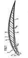
- the compressor blade comprises a highly rigid blade core 1 made of a fiber composite material, a metallic sheath 2 with a leading edge molding 3 and a blade root (not shown) via which the compressor blade is connected to a disc (not shown).
- the fiber composite material of the blade core is used in a known manner as a support structure for receiving the centrifugal forces and the bending and torsional load and for vibration damping and finally to reduce weight compared to the massively made of metal compressor blades.
- the metallic sheath 2 consists of a provided on the pressure side of the compressor blade first cover plate 5 and provided on the suction side of the compressor blade second cover plate 4.
- a metal mesh 6 is fixed in each case via a intimate, firm connection between the cover plates 4, 5 and the fiber composite material of the blade core 1 is produced.
- this intimate connection between the cover sheets and the fiber composite material may also be pretreated by manners known in the art such as, for example, etching or roughening the sheets.
- the cover sheets 4, 5 are capable of absorbing some of the impact forces and erosion stress caused by bird strike or impinging sand or hailstones. Since the beat and However, if the blade's leading edge (air inlet edge) erosion effects are particularly large, a conventionally manufactured blade could be destroyed by bird strikes or damaged by erosion, corrosion and cracking gradually progressing in this sensitive area, thereby also affecting the blade core 1. To prevent this, the two cover plates 4 and 5 are connected to each other at the leading edge of the blade via a leading edge molding 3.
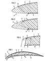
- the leading edge molding 3 is made of solid metal, such as austenitic steel, and has at the edges of the cover plates 4, 5 facing side each one of the length and thickness of the respective cover plate corresponding recess 7.
- the front edge of the respective cover plate 4, 5 with the leading edge molding 3 by welding, for example laser or diffusion welding, connected, in such a way that the outer surface of the leading edge molding 3 flush with the outer surface of the respective cover plate closes and thus the transition between cover plate and leading edge molding is not notch sensitive.
- the leading edge molding 3 is formed so that the two welds 8 and 9, via which the cover plates 4, 5 are connected to the leading edge molding 3, offset from one another.
- the weld inspection can be done without mutual interference.
- this connection point between the leading edge molding 3 and the cover plate 5 (pressure side) is not stressed too much.
- a groove (recess) 10 is formed in the blade core 1 (fiber composite material) facing surface of the leading edge molding 3 to provide a large contact surface and thus the best possible connection with the fiber composite material and also the Mass of the leading edge molding 3, especially if this is very long or thick formed to reduce. It is understood that the sizing of the leading edge molding 3 is variable and, for example, with a very small radius at the tip, can be designed to achieve optimum aerodynamic properties.
- a further embodiment of the leading edge molding 3 is shown, at its side facing the blade core a projecting into the fiber composite material fastening web 11 is formed, which may be wedge-shaped to the blade core 1 out to an intimate connection between the blade core 1 and To create leading edge molding 3.
- the fastening web 11 is provided with fastening holes 12, via which the fiber material is connected to the fastening web 11.
- the fastening web 11 may also have other profiles, structuring or anchoring elements for producing a firm connection between the leading edge molding 3 and the blade core 1.
- the load on the compressor blade is greater on the pressure side than on the suction side and near the leading edge in turn larger than in one from this more distant area.
- the multi-part metallic sheath 2 consisting of the leading edge molding and the two cover plates, creates the possibility of producing the various components of the sheath from different, matched to the respective load materials or form the cover plates each in different sheet thickness.
- This design makes it possible to produce the cover plates and the leading edge molding from each adapted to the requirements, different materials.
- Nickel base materials, austenitic steels and titanium base materials are particularly suitable.
- the cover plate 5 Due to the high load in the area close to the guide edge on the pressure side, the cover plate 5, as shown in FIG. 1, has variable wall thicknesses s1, s2,..., So-called "tailored sheets" (taylored blanks). The area with the larger wall thickness s1 then directly adjoins the leading edge molding 3.
- the length of the leading edge molding 3 is variable depending on the expected load. Also, the profile of the leading edge molding, as shown in FIG. 3, be shaped so that more material than on the suction side is present on the pressure side.
- compressor blade with a constructed of the individual elements 3, 4 and 5 metallic sheath 2 can be formed according to the respective load conditions in terms of material thickness, material type and shape of the leading edge so that at maximum necessary weight high stability and a long Lifespan and optimal aerodynamic properties are guaranteed.
- One of the most likely to occur in the highest loaded leading edge area cracking or material weakening or damage by erosion or corrosion can be inexpensively repaired by replacing the leading edge molding 3 or by applying material.
Landscapes
- Engineering & Computer Science (AREA)
- Mechanical Engineering (AREA)
- General Engineering & Computer Science (AREA)
- Chemical & Material Sciences (AREA)
- Materials Engineering (AREA)
- Architecture (AREA)
- Composite Materials (AREA)
- Aviation & Aerospace Engineering (AREA)
- Structures Of Non-Positive Displacement Pumps (AREA)
Claims (9)
- Aube de compresseur pour un moteur d'avion, dont la pale comprend une âme (1) en matériau composite renforcé par des fibres et une enveloppe métallique en plusieurs parties (2), composée d'une pièce façonnée de bord d'attaque (3) et de tôles de recouvrement (4, 5) soudées en bout à celle-ci et disposées sur les côtés refoulement et aspiration, sachant que la pièce façonnée de bord d'attaque (3) en métal massif présente en direction de l'âme d'aube (1) une cannelure (10) dans laquelle pénètre le matériau renforcé par des fibres, a une forme asymétrique en coupe transversale et est plus longue du côté refoulement que du côté aspiration, sachant que la soudure (9) se trouvant sur le côté refoulement est plus éloignée du bord d'attaque que la soudure (8) se trouvant sur le côté aspiration, et que la pièce façonnée de bord d'attaque (3) présente une épaisseur de matériau plus importante du côté refoulement que du côté aspiration.
- Aube de compresseur selon la revendication nº 1, caractérisée en ce que l'épaisseur des deux tôles de recouvrement (4, 5) ou d'une seule et même tôle de recouvrement varie entre le bord d'attaque et le bord de fuite en fonction de la contrainte.
- Aube de compresseur selon la revendication nº 2, caractérisée en ce que la tôle de recouvrement (5) du côté refoulement présente une épaisseur de matériau plus importante que la tôle de recouvrement (4) du côté aspiration.
- Aube de compresseur selon la revendication n° 3, caractérisée en ce que la tôle de recouvrement (5) du côté refoulement présente, dans la zone avant en liaison avec la pièce façonnée de bord d'attaque (3), une épaisseur plus importante que dans la zone arrière.
- Aube de compresseur selon la revendication nº 1, caractérisée en ce qu'une barrette de fixation (11) pénétrant dans le matériau composite renforcé par des fibres est formée sur la pièce façonnée de bord d'attaque (3), et élargie de façon cunéiforme en direction de l'âme d'aube (1) pour une liaison étroite avec le matériau composite renforcé par des fibres et/ou présente des structures de surface ou des orifices de fixation (12).
- Aube de compresseur selon la revendication n° 1, caractérisée en ce que la pièce façonnée de bord d'attaque (3) présente des évidements (7) destinés à loger les extrémités des tôles de recouvrement (4, 5).
- Aube de compresseur selon la revendication nº 1, caractérisée en ce que les différentes parties (3 à 5) de l'enveloppe (2) sont composées de différents métaux ou alliages métalliques en fonction de la contrainte respective.
- Aube de compresseur selon la revendication nº 1, caractérisée en ce que des matériaux à base de nickel, des aciers austénitiques ou des matériaux à base de titane sont utilisés pour la fabrication des tôles de recouvrement (4, 5) et de la pièce façonnée de bord d'attaque (3).
- Aube de compresseur selon la revendication nº 1, caractérisée en ce que l'enveloppe métallique présente une toile métallique (6) sur la face tournée vers l'âme d'aube.
Applications Claiming Priority (2)
| Application Number | Priority Date | Filing Date | Title |
|---|---|---|---|
| DE10307610 | 2003-02-22 | ||
| DE10307610A DE10307610A1 (de) | 2003-02-22 | 2003-02-22 | Verdichterschaufel für ein Flugzeugtriebwerk |
Publications (2)
| Publication Number | Publication Date |
|---|---|
| EP1450006A1 EP1450006A1 (fr) | 2004-08-25 |
| EP1450006B1 true EP1450006B1 (fr) | 2006-04-05 |
Family
ID=32731101
Family Applications (1)
| Application Number | Title | Priority Date | Filing Date |
|---|---|---|---|
| EP04090042A Expired - Lifetime EP1450006B1 (fr) | 2003-02-22 | 2004-02-11 | Aube de compresseur pour un moteur d'avion |
Country Status (3)
| Country | Link |
|---|---|
| US (1) | US7156622B2 (fr) |
| EP (1) | EP1450006B1 (fr) |
| DE (2) | DE10307610A1 (fr) |
Cited By (1)
| Publication number | Priority date | Publication date | Assignee | Title |
|---|---|---|---|---|
| WO2012131100A1 (fr) | 2011-04-01 | 2012-10-04 | Rolls-Royce Deutschland Ltd & Co Kg | Procédé de fabrication d'une pièce, la pièce même et turbomachine munie d'une telle pièce |
Families Citing this family (51)
| Publication number | Priority date | Publication date | Assignee | Title |
|---|---|---|---|---|
| DE102004052142B4 (de) * | 2004-10-22 | 2009-05-28 | Rolls-Royce Deutschland Ltd & Co Kg | Laserschweißverfahren zur Herstellung von aus einem Blechmantel und einem Faserverbund bestehenden Verdichterschaufeln für ein Gasturbinentriebwerk |
| RU2282726C1 (ru) * | 2005-01-24 | 2006-08-27 | Федеральное государственное унитарное предприятие "Центральный институт авиационного моторостроения им. П.И. Баранова" | Композиционная лопатка турбомашины |
| DE102005061673A1 (de) | 2005-12-21 | 2007-07-05 | Rolls-Royce Deutschland Ltd & Co Kg | Vorderkantenausbildung für die Verdichterschaufeln von Gasturbinentriebwerken |
| GB0605070D0 (en) * | 2006-03-14 | 2006-04-26 | Rolls Royce Plc | An aerofoil |
| US7780420B1 (en) * | 2006-11-16 | 2010-08-24 | Florida Turbine Technologies, Inc. | Turbine blade with a foam metal leading or trailing edge |
| DE102006061916A1 (de) * | 2006-12-21 | 2008-06-26 | Rolls-Royce Deutschland Ltd & Co Kg | Fanschaufel für ein Gasturbinentriebwerk |
| DE102006061915A1 (de) | 2006-12-21 | 2008-07-03 | Rolls-Royce Deutschland Ltd & Co Kg | Hybrid-Fanschaufel und Verfahren zu deren Herstellung |
| US7753653B2 (en) * | 2007-01-12 | 2010-07-13 | General Electric Company | Composite inlet guide vane |
| US7980817B2 (en) * | 2007-04-16 | 2011-07-19 | United Technologies Corporation | Gas turbine engine vane |
| US7805839B2 (en) * | 2007-12-31 | 2010-10-05 | Turbine Engine Components Technologies Corporation | Method of manufacturing a turbine fan blade |
| DE102008021684A1 (de) | 2008-04-30 | 2009-11-05 | Rolls-Royce Deutschland Ltd & Co Kg | Leitschaufeln eines Leitschaufelgitters einer Fluggasturbine |
| US8146250B2 (en) * | 2008-05-30 | 2012-04-03 | General Electric Company | Method of replacing a composite airfoil |
| US8241001B2 (en) * | 2008-09-04 | 2012-08-14 | Siemens Energy, Inc. | Stationary turbine component with laminated skin |
| DE102008058786A1 (de) * | 2008-11-24 | 2010-05-27 | Rolls-Royce Deutschland Ltd & Co Kg | Hybrides Bauteil für ein Gasturbinentriebwerk |
| US20110110772A1 (en) * | 2009-11-11 | 2011-05-12 | Arrell Douglas J | Turbine Engine Components with Near Surface Cooling Channels and Methods of Making the Same |
| FR2957545B1 (fr) * | 2010-03-19 | 2012-07-27 | Snecma | Procede de realisation d'un insert metallique pour la protection d'un bord d'attaque en materiau composite |
| US9376917B2 (en) * | 2010-07-15 | 2016-06-28 | Ihi Corporation | Fan rotor blade and fan |
| US20120021243A1 (en) * | 2010-07-23 | 2012-01-26 | General Electric Company | Components with bonded edges |
| DE102010032097A1 (de) | 2010-07-23 | 2012-01-26 | Formtech Gmbh | Verdichterschaufel eines Gasturbinentriebwerks mit selbstschärfender Vorderkantenstruktur |
| FR2964411B1 (fr) * | 2010-09-06 | 2012-08-24 | Messier Dowty Sa | Aube de turboreacteur, notamment une aube de redresseur, et turboreacteur recevant de telles aubes |
| FR2965824B1 (fr) * | 2010-10-11 | 2013-11-15 | Snecma | Procede de fabrication d'une structure fibreuse metallique par tissage |
| WO2012061573A1 (fr) * | 2010-11-05 | 2012-05-10 | Barnes Group Inc. | Pièce à bord d'attaque en métal hybride et procédé de fabrication de celle-ci |
| FR2970196B1 (fr) * | 2011-01-10 | 2012-12-28 | Snecma | Procede de realisation d'un renfort metallique |
| FR2970668B1 (fr) * | 2011-01-24 | 2013-01-18 | Snecma | Procede de realisation d'un renfort metallique |
| CH705171A1 (de) * | 2011-06-21 | 2012-12-31 | Alstom Technology Ltd | Turbinenschaufel mit einem Schaufelblatt aus Verbundwerkstoff und Verfahren zum Herstellen davon. |
| US9279328B2 (en) * | 2011-10-25 | 2016-03-08 | Whitcraft Llc | Airfoil devices, leading edge components, and methods of making |
| FR2989991B1 (fr) * | 2012-04-30 | 2016-01-08 | Snecma | Renfort structurel metallique d'aube de turbomachine |
| US8968437B2 (en) * | 2012-05-02 | 2015-03-03 | Michael J Kline | Jet engine with deflector |
| FR2991206B1 (fr) | 2012-06-01 | 2014-06-20 | Snecma | Procede de realisation d'un renfort metallique d'une aube de turbomachine |
| EP2870364B1 (fr) * | 2012-07-03 | 2018-11-28 | GKN Aerospace Sweden AB | Structure de support pour un moteur de turbine à gaz |
| DE102012015137A1 (de) * | 2012-07-30 | 2014-02-13 | Rolls-Royce Deutschland Ltd & Co Kg | Niedermodulige Gasturbinenverdichterschaufel |
| DE102012015135A1 (de) | 2012-07-30 | 2014-02-13 | Rolls-Royce Deutschland Ltd & Co Kg | Verdichterschaufel einer Gasturbine sowie Verfahren zu deren Herstellung |
| US9470097B2 (en) | 2013-03-14 | 2016-10-18 | Rolls-Royce Corporation | Airfoil with leading edge reinforcement |
| FR3008920B1 (fr) * | 2013-07-29 | 2015-12-25 | Safran | Procede de fabrication d'une aube en materiau composite a bord d'attaque metallique integre pour moteur aeronautique a turbine a gaz |
| FR3010132A1 (fr) * | 2013-09-04 | 2015-03-06 | Safran | Bord d'attaque metallique d'aube en materiau composite pour moteur a turbine a gaz |
| FR3011269B1 (fr) * | 2013-09-30 | 2018-02-09 | Safran | Aube de redresseur pour moteur a turbine a gaz a structure hybride |
| FR3011875B1 (fr) * | 2013-10-11 | 2018-04-20 | Snecma | Aube de turbomachine a profil asymetrique |
| US9896941B2 (en) * | 2014-01-16 | 2018-02-20 | United Technologies Corporation | Fan blade composite cover with tapered edges |
| DE102015203765A1 (de) * | 2015-03-03 | 2016-09-08 | Siemens Aktiengesellschaft | Massives hohles Bauteil mit Blech zur Erzeugung eines Hohlraums |
| DE102015203868A1 (de) | 2015-03-04 | 2016-09-08 | Rolls-Royce Deutschland Ltd & Co Kg | Fanschaufel für einen Flugantrieb |
| BE1022809B1 (fr) | 2015-03-05 | 2016-09-13 | Techspace Aero S.A. | Aube composite de compresseur de turbomachine axiale |
| BE1023290B1 (fr) * | 2015-07-22 | 2017-01-24 | Safran Aero Boosters S.A. | Aube composite de compresseur de turbomachine axiale |
| FR3041684B1 (fr) * | 2015-09-28 | 2021-12-10 | Snecma | Aube comprenant un bouclier de bord d'attaque et procede de fabrication de l'aube |
| US10570917B2 (en) * | 2016-08-01 | 2020-02-25 | United Technologies Corporation | Fan blade with composite cover |
| JP2019172051A (ja) * | 2018-03-28 | 2019-10-10 | ヤマハ発動機株式会社 | ブレードおよびそれを備える機器 |
| CN110344887B (zh) * | 2018-04-03 | 2022-02-18 | 中国航发商用航空发动机有限责任公司 | 混合材料风扇叶片及其制备方法 |
| FR3085414B1 (fr) * | 2018-08-30 | 2021-01-29 | Safran Aircraft Engines | Aube de turbomachine comportant une liaison au renfort structurel a inserts et evidements |
| US10822969B2 (en) * | 2018-10-18 | 2020-11-03 | Raytheon Technologies Corporation | Hybrid airfoil for gas turbine engines |
| US11286782B2 (en) | 2018-12-07 | 2022-03-29 | General Electric Company | Multi-material leading edge protector |
| US11149581B2 (en) * | 2019-11-22 | 2021-10-19 | Rolls-Royce Plc | Turbine engine component with overstress indicator |
| CN114439614A (zh) * | 2020-10-30 | 2022-05-06 | 中国航发商用航空发动机有限责任公司 | 航空发动机的风扇叶片和航空发动机 |
Family Cites Families (18)
| Publication number | Priority date | Publication date | Assignee | Title |
|---|---|---|---|---|
| US2734586A (en) * | 1956-02-14 | Low-density propeller blade | ||
| GB950434A (en) * | 1961-02-14 | 1964-02-26 | Macard Screws Ltd | The construction of aerofoil blades for radial flow fans |
| US3466725A (en) * | 1964-01-03 | 1969-09-16 | Wilson Shipyard Inc | Method of forming a hydrofoil |
| GB1040825A (en) * | 1965-04-20 | 1966-09-01 | Rolls Royce | Improvements in rotor blades and/or stator blades for gas turbine engines |
| GB1130285A (en) * | 1967-05-05 | 1968-10-16 | Rolls Royce | Method of making an aerofoil shaped blade for a fluid flow machine |
| GB1186486A (en) * | 1968-10-22 | 1970-04-02 | Rolls Royce | Fibre Reinforced Blade |
| GB1284538A (en) * | 1968-11-19 | 1972-08-09 | Rolls Royce | Blade for a fluid flow machine |
| GB1276458A (en) * | 1969-05-12 | 1972-06-01 | Cyclops Corp | Hollow members |
| US3695778A (en) * | 1970-09-18 | 1972-10-03 | Trw Inc | Turbine blade |
| US4006999A (en) * | 1975-07-17 | 1977-02-08 | The United States Of America As Represented By The Administrator Of The National Aeronautics And Space Administration | Leading edge protection for composite blades |
| IT1176673B (it) | 1983-09-23 | 1987-08-18 | Gen Electric | Pala cava per turbomacchina |
| US4738594A (en) * | 1986-02-05 | 1988-04-19 | Ishikawajima-Harima Jukogyo Kabushiki Kaisha | Blades for axial fans |
| DE4225599A1 (de) * | 1992-08-03 | 1994-02-17 | Harald Dr Kayser | Tragflügel für Windenergieanlage |
| FR2705603B1 (fr) * | 1993-05-25 | 1995-06-30 | Snecma | Procédé de soudage laser d'un assemblage de deux pièces métalliques. |
| US5486096A (en) * | 1994-06-30 | 1996-01-23 | United Technologies Corporation | Erosion resistant surface protection |
| US6155783A (en) * | 1998-05-20 | 2000-12-05 | Voith Siemens Hydro Power Generation, Inc. | Hollow blade for hydraulic turbine or pump |
| US6431837B1 (en) * | 1999-06-01 | 2002-08-13 | Alexander Velicki | Stitched composite fan blade |
| US6431831B1 (en) * | 1999-08-20 | 2002-08-13 | Giw Industries, Inc. | Pump impeller with enhanced vane inlet wear |
-
2003
- 2003-02-22 DE DE10307610A patent/DE10307610A1/de not_active Withdrawn
-
2004
- 2004-02-11 EP EP04090042A patent/EP1450006B1/fr not_active Expired - Lifetime
- 2004-02-11 DE DE502004000409T patent/DE502004000409D1/de not_active Expired - Lifetime
- 2004-02-19 US US10/780,882 patent/US7156622B2/en not_active Expired - Fee Related
Cited By (1)
| Publication number | Priority date | Publication date | Assignee | Title |
|---|---|---|---|---|
| WO2012131100A1 (fr) | 2011-04-01 | 2012-10-04 | Rolls-Royce Deutschland Ltd & Co Kg | Procédé de fabrication d'une pièce, la pièce même et turbomachine munie d'une telle pièce |
Also Published As
| Publication number | Publication date |
|---|---|
| DE10307610A1 (de) | 2004-09-02 |
| US20040184921A1 (en) | 2004-09-23 |
| US7156622B2 (en) | 2007-01-02 |
| DE502004000409D1 (de) | 2006-05-18 |
| EP1450006A1 (fr) | 2004-08-25 |
Similar Documents
| Publication | Publication Date | Title |
|---|---|---|
| EP1450006B1 (fr) | Aube de compresseur pour un moteur d'avion | |
| DE2756684C2 (de) | Verfahren zum Fertigen einer Turbomaschinenschaufel und Strömungsturbomaschine mit derartigen Schaufeln | |
| EP1914383B1 (fr) | Aube de soufflante en matériau composite | |
| EP1032749B1 (fr) | Rotor a aubes integrees | |
| EP1439281B1 (fr) | Aube de turbine à gaz | |
| DE3879561T2 (de) | Strebe mit kreuzquerschnitt. | |
| DE60023979T2 (de) | Bläserplattform | |
| DE19535713B4 (de) | Verbundschaufel | |
| DE2753773A1 (de) | Laufschaufel | |
| EP0899426B1 (fr) | Aube de guidage pour turbines à gaz | |
| DE602004006323T2 (de) | Verfahren zur Herstellung einer Turbine mit Turbinenschaufeln unterschiedlicher Resonanzfrequenzen samt einer solchen Turbine | |
| DE1752234A1 (de) | Verfahren zum Herstellen einer stromlinienfoermigen Schaufel fuer Stroemungsmaschinen | |
| EP1939402A2 (fr) | Aube de soufflante en matériau composite pour un moteur à turbine à gaz | |
| DE2644083A1 (de) | Verbund-laufschaufel unter verwendung eines vorgespannten lagenaufbaus | |
| DE102013219774A1 (de) | Schaufel für eine Gasturbine | |
| DE602004007071T2 (de) | Zwischenschaufelplattformen mit elastischen Seitenkanten | |
| DE102015203868A1 (de) | Fanschaufel für einen Flugantrieb | |
| DE102008021684A1 (de) | Leitschaufeln eines Leitschaufelgitters einer Fluggasturbine | |
| EP2404038B1 (fr) | Rotor à aubage intégral et procede de fabrication d'un rotor à aubage intégral | |
| EP1524407B1 (fr) | Aube de soufflante creuse et sa méthode de production | |
| EP2087149A2 (fr) | Aube pour compresseur ou turbine d'un turboréacteur, turboréacteur présentant une telle aube, et procédé de recouvrement d'une aube de turboréacteur | |
| WO2009100795A1 (fr) | Aube mobile pour une turbomachine | |
| DE102018212334B4 (de) | Abgasturbolader mit Turbinenrad mit Winglets | |
| DE102021109844A1 (de) | Gasturbinen-Schaufelanordnung | |
| DE102021200287A1 (de) | Zellenartiger Belag und Schaufelanordnung für eine Turbomaschine |
Legal Events
| Date | Code | Title | Description |
|---|---|---|---|
| PUAI | Public reference made under article 153(3) epc to a published international application that has entered the european phase |
Free format text: ORIGINAL CODE: 0009012 |
|
| AK | Designated contracting states |
Kind code of ref document: A1 Designated state(s): AT BE BG CH CY CZ DE DK EE ES FI FR GB GR HU IE IT LI LU MC NL PT RO SE SI SK TR |
|
| AX | Request for extension of the european patent |
Extension state: AL LT LV MK |
|
| 17P | Request for examination filed |
Effective date: 20040909 |
|
| 17Q | First examination report despatched |
Effective date: 20041104 |
|
| AKX | Designation fees paid |
Designated state(s): DE FR GB |
|
| RBV | Designated contracting states (corrected) |
Designated state(s): DE FR GB |
|
| GRAP | Despatch of communication of intention to grant a patent |
Free format text: ORIGINAL CODE: EPIDOSNIGR1 |
|
| GRAS | Grant fee paid |
Free format text: ORIGINAL CODE: EPIDOSNIGR3 |
|
| GRAA | (expected) grant |
Free format text: ORIGINAL CODE: 0009210 |
|
| AK | Designated contracting states |
Kind code of ref document: B1 Designated state(s): DE FR GB |
|
| REG | Reference to a national code |
Ref country code: GB Ref legal event code: FG4D Free format text: NOT ENGLISH |
|
| REF | Corresponds to: |
Ref document number: 502004000409 Country of ref document: DE Date of ref document: 20060518 Kind code of ref document: P |
|
| GBT | Gb: translation of ep patent filed (gb section 77(6)(a)/1977) |
Effective date: 20060502 |
|
| ET | Fr: translation filed | ||
| PLBE | No opposition filed within time limit |
Free format text: ORIGINAL CODE: 0009261 |
|
| STAA | Information on the status of an ep patent application or granted ep patent |
Free format text: STATUS: NO OPPOSITION FILED WITHIN TIME LIMIT |
|
| 26N | No opposition filed |
Effective date: 20070108 |
|
| REG | Reference to a national code |
Ref country code: FR Ref legal event code: PLFP Year of fee payment: 13 |
|
| REG | Reference to a national code |
Ref country code: FR Ref legal event code: PLFP Year of fee payment: 14 |
|
| PGFP | Annual fee paid to national office [announced via postgrant information from national office to epo] |
Ref country code: FR Payment date: 20170223 Year of fee payment: 14 Ref country code: DE Payment date: 20170227 Year of fee payment: 14 |
|
| PGFP | Annual fee paid to national office [announced via postgrant information from national office to epo] |
Ref country code: GB Payment date: 20170227 Year of fee payment: 14 |
|
| REG | Reference to a national code |
Ref country code: DE Ref legal event code: R119 Ref document number: 502004000409 Country of ref document: DE |
|
| GBPC | Gb: european patent ceased through non-payment of renewal fee |
Effective date: 20180211 |
|
| REG | Reference to a national code |
Ref country code: FR Ref legal event code: ST Effective date: 20181031 |
|
| PG25 | Lapsed in a contracting state [announced via postgrant information from national office to epo] |
Ref country code: DE Free format text: LAPSE BECAUSE OF NON-PAYMENT OF DUE FEES Effective date: 20180901 |
|
| PG25 | Lapsed in a contracting state [announced via postgrant information from national office to epo] |
Ref country code: FR Free format text: LAPSE BECAUSE OF NON-PAYMENT OF DUE FEES Effective date: 20180228 Ref country code: GB Free format text: LAPSE BECAUSE OF NON-PAYMENT OF DUE FEES Effective date: 20180211 |