EP1450035A2 - Injecteur de carburant - Google Patents
Injecteur de carburant Download PDFInfo
- Publication number
- EP1450035A2 EP1450035A2 EP04010847A EP04010847A EP1450035A2 EP 1450035 A2 EP1450035 A2 EP 1450035A2 EP 04010847 A EP04010847 A EP 04010847A EP 04010847 A EP04010847 A EP 04010847A EP 1450035 A2 EP1450035 A2 EP 1450035A2
- Authority
- EP
- European Patent Office
- Prior art keywords
- swirl
- fuel
- flow rate
- channels
- valve seat
- Prior art date
- Legal status (The legal status is an assumption and is not a legal conclusion. Google has not performed a legal analysis and makes no representation as to the accuracy of the status listed.)
- Withdrawn
Links
Images

Classifications
-
- F—MECHANICAL ENGINEERING; LIGHTING; HEATING; WEAPONS; BLASTING
- F02—COMBUSTION ENGINES; HOT-GAS OR COMBUSTION-PRODUCT ENGINE PLANTS
- F02M—SUPPLYING COMBUSTION ENGINES IN GENERAL WITH COMBUSTIBLE MIXTURES OR CONSTITUENTS THEREOF
- F02M61/00—Fuel-injectors not provided for in groups F02M39/00 - F02M57/00 or F02M67/00
- F02M61/16—Details not provided for in, or of interest apart from, the apparatus of groups F02M61/02 - F02M61/14
- F02M61/168—Assembling; Disassembling; Manufacturing; Adjusting
-
- F—MECHANICAL ENGINEERING; LIGHTING; HEATING; WEAPONS; BLASTING
- F02—COMBUSTION ENGINES; HOT-GAS OR COMBUSTION-PRODUCT ENGINE PLANTS
- F02M—SUPPLYING COMBUSTION ENGINES IN GENERAL WITH COMBUSTIBLE MIXTURES OR CONSTITUENTS THEREOF
- F02M51/00—Fuel-injection apparatus characterised by being operated electrically
- F02M51/06—Injectors peculiar thereto with means directly operating the valve needle
- F02M51/061—Injectors peculiar thereto with means directly operating the valve needle using electromagnetic operating means
- F02M51/0625—Injectors peculiar thereto with means directly operating the valve needle using electromagnetic operating means characterised by arrangement of mobile armatures
- F02M51/0664—Injectors peculiar thereto with means directly operating the valve needle using electromagnetic operating means characterised by arrangement of mobile armatures having a cylindrically or partly cylindrically shaped armature, e.g. entering the winding; having a plate-shaped or undulated armature entering the winding
-
- F—MECHANICAL ENGINEERING; LIGHTING; HEATING; WEAPONS; BLASTING
- F02—COMBUSTION ENGINES; HOT-GAS OR COMBUSTION-PRODUCT ENGINE PLANTS
- F02M—SUPPLYING COMBUSTION ENGINES IN GENERAL WITH COMBUSTIBLE MIXTURES OR CONSTITUENTS THEREOF
- F02M61/00—Fuel-injectors not provided for in groups F02M39/00 - F02M57/00 or F02M67/00
- F02M61/16—Details not provided for in, or of interest apart from, the apparatus of groups F02M61/02 - F02M61/14
- F02M61/162—Means to impart a whirling motion to fuel upstream or near discharging orifices
-
- F—MECHANICAL ENGINEERING; LIGHTING; HEATING; WEAPONS; BLASTING
- F02—COMBUSTION ENGINES; HOT-GAS OR COMBUSTION-PRODUCT ENGINE PLANTS
- F02M—SUPPLYING COMBUSTION ENGINES IN GENERAL WITH COMBUSTIBLE MIXTURES OR CONSTITUENTS THEREOF
- F02M61/00—Fuel-injectors not provided for in groups F02M39/00 - F02M57/00 or F02M67/00
- F02M61/16—Details not provided for in, or of interest apart from, the apparatus of groups F02M61/02 - F02M61/14
- F02M61/165—Filtering elements specially adapted in fuel inlets to injector
Definitions
- the invention is based on a fuel injector according to the genus of the main claim.
- Fuel injectors which have a disc for Determination of a metering quantity as a component are off known from DE 36 43 523 A1. You have a disc in the fuel channels are introduced. This Fuel channels have a tangential component that the velocity vector of the flow with a Circumferential component provides. The through the total cross section of the fuel channels open flow cross section acts limiting to the flow rate. The throttling of the Flow creates a pressure drop across the disc leading to the Formation of a sealing surface pressure and Avoidance of secondary flow paths is used. The metering of the fuel and, if necessary, the formation of a Swirls take place upstream of the sealing seat.
- DE 196 25 059 A1 is another Fuel injector known in which the metering of Amount of fuel also upstream of the sealing seat he follows.
- the fuel channels through which the metering of the Fuel takes place, are arranged so that at open valve several jets directly through the Hit the valve spray port. The one in the combustion chamber injected fuel can thus be targeted in strands be delivered.
- Fuel injector has one with a blind hole provided valve closing body, inside of which the Fuel reaches up to the valve seat surface. at When the fuel injector is open, the fuel enters through radially arranged flow channels from the Valve closing body, impacts the valve seat and then emerges from the fuel injector.
- the fuel injector according to the invention with the characteristic features of claim 1 has in contrast the advantage that the metering of the fuel does not have the cross-sectional area of the swirl channels takes place.
- the swirl disc can therefore be done using processes be used where the dimensional accuracy of the individual Bore diameter is small. Such procedures work usually quickly and inexpensively.
- Another advantage is the small change in the Injection pattern both in terms of the metered amount and the spray angle over the life of the Fuel injector. Dirt particles that are in the Fuel can cause constipation Lead swirl channels. In the embodiment according to the invention this is due to the high number of swirl channels a minor change in Total cross section of the swirl channels, which is made up of a Large number of individual swirl channels. Through the Metering of the fuel in the immediate there is no subsequent swirl chamber Quantity change. Also in the further flow path can do not form deposits. Due to the high Flow rate of the fuel in the Swirl chamber is maintained, deposits prevented.
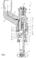
- the fuel injector 1 is in the form of a Fuel injection valve for fuel injection systems of mixture-compressing, spark-ignited Running internal combustion engines.
- the Fuel injection valve 1 is particularly suitable for not directly injecting fuel into one Shown combustion chamber of an internal combustion engine.
- the fuel injector 1 consists of a Nozzle body 2, in which a valve needle 3 is arranged.
- the valve needle 3 is operatively connected to a Valve closing body 4 with one on one Valve seat body 5 arranged valve seat surface 6 into one Sealing seat interacts.
- the fuel injector 1 in the exemplary embodiment it is an inward opening electromagnetically operated Fuel injector 1, which has a Spray opening 7 has.
- the nozzle body 2 is through a Seal 8 against the outer pole 9 of a magnetic coil 10 sealed.
- the magnet coil 10 is in a coil housing 11 encapsulated and wound on a bobbin 12, which bears against an inner pole 13 of the magnet coil 10.
- the Inner pole 13 and outer pole 9 are through a gap 26 separated from each other and are based on one Connecting component 29 from.
- the solenoid 10 is a Line 19 from via an electrical plug contact 17th supplyable electric current excited.
- the plug contact 17 is surrounded by a plastic sheath 18, which on Inner pole 13 can be molded.
- the valve needle 3 is in a valve needle guide 14 led, which is disc-shaped.
- a paired shim 15 is used for stroke adjustment the other side of the shim 15 is a Anchor 20.
- This stands over a first flange 21 non-positively in connection with the valve needle 3, which through a weld seam 22 with the first flange 21 connected is.
- One is supported on the first flange 21 Return spring 23, which in the present design of the Fuel injector 1 through a sleeve 24 Bias is brought.
- a second flange 31, which is connected to the valve needle 3 is also connected via a weld 33, serves as lower anchor stop.
- An elastic intermediate ring 32, which rests on the second flange 31 is avoided Bouncing when the fuel injector 1 closes.
- valve needle guide 14 in the armature 20 and in the Swirl disk 35 extend fuel channels 30a, 30b or Swirl channels 36 the fuel, which has a central fuel supply 16 and supplied by a Filter element 25 is filtered to the spray opening 7 in direct the valve seat body 5.
- the fuel injector 1 is by a seal 28 against a not shown Distribution line sealed.
- the fuel is metered at the Fuel injection valve 1 designed according to the invention by limiting the flow through a cylinder jacket surface flowing through in the swirl chamber 37, which are connected to a swirl disk 35, as in FIG shown, located.
- FIG. 2 shows an excerpt of a sectional illustration first embodiment of the swirl disk 35 with subsequent swirl chamber 37 of an inventive Fuel injector 1.
- the swirl disk 35 is disk-shaped and is in one cylindrical recess 40 of the valve seat body 5 fixed. For attachment, the swirl disk 35 for example, be pressed into the valve seat body 5. In Axial direction remains between valve seat body 5 and Swirl disk 35 a gap of height h.
- the swirl disk 35 has a central bore 38 for guiding the Valve closing body 4. The bore 38 is opposite Diameter of the valve closing body 4 tolerated so that a between valve closing body 4 and swirl disk 35 as Secondary flow path for the fuel-forming gap is prevented.
- a flow is in the swirl disk 35 for flow guidance Introduced a plurality of swirl channels 36, the central axis 41 face each other at the same or different angles the central axis 42 of the fuel injector 1 can.
- the way trained swirl of the fuel leads to the cumshot Fuel on a cone jacket, the opening angle of the formation of the swirl in the swirl chamber 37 depends.
- the swirl chamber 37 is cylindrical and is in the height h through the valve seat body 5 and the swirl disk 35 limited.
- the relevant one for metering the fuel Throttle point is through a cylindrical surface, which is preferably at least a factor of 1.5 smaller than the sum of the cross-sectional areas of the swirl channels 36, educated.
- the diameter of the swirl channels 36 is smaller than that Diameter of dirt particles that are in the fuel are located.
- the swirl disk 35 thus complements the function of Filters 25.
- the height h of the swirl chamber 37 is determined by a stop 39 fixed.
- the swirl disk 35 is so far in the Valve seat body 5 introduced until it stops at the stop 39 is applied.
- the stop 39 can be in the form of a cylindrical recess 40 of the valve seat body 5 protruding annular paragraph be designed.
- the swirl disk 35 can be in axial direction within the cylindrical recess in Valve seat body 5 positioned as desired and fixed there e.g. by a press connection with the Valve seat body 5.
- an inventive Method for adjusting fuel injector 1 finds the limiting throttling of the fuel flow through the total cross section of the swirl channels 36 instead of.
- the swirl channels 36 are introduced in FIG several steps. First, a certain number of Swirl channels 36 are introduced into swirl disk 35. you The calculated total cross section is dimensioned so that it is smaller than that required for the throttle point. The exact adherence to the individual diameters plays a role a minor role. After the swirl channels 36 have been introduced the swirl disk 35 is pressurized on one side and e.g. by measuring a pressure drop on the swirl disk 35 an actual flow rate is determined. To the formation of Residues during the manufacture of the swirl disc flow measurement, e.g. done pneumatically. The actual flow rate is below a predetermined target flow rate, at least introduced another swirl channel 36. The introduction of the Swirl channels can e.g. by drilling with a laser.
- the limiting throttle point is set by Position the swirl disk 35 in the valve seat body 5. Die Swirl disk 35 is in up to a predetermined position introduced the valve seat body. The actual flow rate through the swirl chamber 37 is measured. If the Actual flow rate from a specified target flow rate becomes the axial position of the swirl disk 35 changed in the valve seat body 5 so that the height of the Swirl chamber 37 when the target flow rate is exceeded reduced, is increased if the value falls below. The measurement the actual flow rate and change in position of the Swirl disk 35 are repeated until the desired flow rate is essentially achieved. The measurement of Actual flow rate can be used to avoid residues e.g. done pneumatically. To reduce the number of Reaching adjustment cycles can be around the target flow rate a tolerance range can be specified when it is reached positioning is ended.
Landscapes
- Engineering & Computer Science (AREA)
- Chemical & Material Sciences (AREA)
- Combustion & Propulsion (AREA)
- Mechanical Engineering (AREA)
- General Engineering & Computer Science (AREA)
- Physics & Mathematics (AREA)
- Electromagnetism (AREA)
- Manufacturing & Machinery (AREA)
- Fuel-Injection Apparatus (AREA)
Applications Claiming Priority (1)
| Application Number | Priority Date | Filing Date | Title |
|---|---|---|---|
| EP20010127172 EP1312794B1 (fr) | 2001-11-16 | 2001-11-16 | Injecteur de carburant |
Related Parent Applications (2)
| Application Number | Title | Priority Date | Filing Date |
|---|---|---|---|
| EP20010127172 Division EP1312794B1 (fr) | 2001-11-16 | 2001-11-16 | Injecteur de carburant |
| EP01127172.3 Division | 2001-11-16 |
Publications (2)
| Publication Number | Publication Date |
|---|---|
| EP1450035A2 true EP1450035A2 (fr) | 2004-08-25 |
| EP1450035A3 EP1450035A3 (fr) | 2004-09-01 |
Family
ID=8179246
Family Applications (2)
| Application Number | Title | Priority Date | Filing Date |
|---|---|---|---|
| EP04010847A Withdrawn EP1450035A3 (fr) | 2001-11-16 | 2001-11-16 | Injecteur de carburant |
| EP20010127172 Expired - Lifetime EP1312794B1 (fr) | 2001-11-16 | 2001-11-16 | Injecteur de carburant |
Family Applications After (1)
| Application Number | Title | Priority Date | Filing Date |
|---|---|---|---|
| EP20010127172 Expired - Lifetime EP1312794B1 (fr) | 2001-11-16 | 2001-11-16 | Injecteur de carburant |
Country Status (2)
| Country | Link |
|---|---|
| EP (2) | EP1450035A3 (fr) |
| DE (1) | DE50105211D1 (fr) |
Family Cites Families (8)
| Publication number | Priority date | Publication date | Assignee | Title |
|---|---|---|---|---|
| US3641802A (en) * | 1969-09-17 | 1972-02-15 | Parker Hannifin Corp | Method and apparatus for setting the flow rate of a fuel injection nozzle |
| DE3506729A1 (de) * | 1984-03-28 | 1985-10-10 | Daimler-Benz Ag, 7000 Stuttgart | Einspritzduese fuer eine luftverdichtende einspritzbrennkraftmaschine |
| DE3418761A1 (de) * | 1984-05-19 | 1985-11-21 | Robert Bosch Gmbh, 7000 Stuttgart | Einspritzventil |
| DE3624477A1 (de) | 1986-07-19 | 1988-01-28 | Bosch Gmbh Robert | Einspritzventil |
| DE3643523A1 (de) * | 1986-12-19 | 1988-06-30 | Bosch Gmbh Robert | Einspritzventil fuer kraftstoffeinspritzanlagen |
| DE4025945C2 (de) * | 1990-08-16 | 1998-10-08 | Bosch Gmbh Robert | Verfahren zur Einstellung eines Brennstoffeinspritzventils und Brennstoffeinspritzventil |
| DE19625059A1 (de) | 1996-06-22 | 1998-01-02 | Bosch Gmbh Robert | Einspritzventil, insbesondere zum direkten Einspritzen von Kraftstoff in einen Brennraum eines Verbrennungsmotors |
| DE19947780A1 (de) * | 1999-10-02 | 2001-04-12 | Bosch Gmbh Robert | Verfahren zum Einstellen der Strömungsmenge an einem Brennstoffeinspritzventil |
-
2001
- 2001-11-16 EP EP04010847A patent/EP1450035A3/fr not_active Withdrawn
- 2001-11-16 DE DE50105211T patent/DE50105211D1/de not_active Expired - Fee Related
- 2001-11-16 EP EP20010127172 patent/EP1312794B1/fr not_active Expired - Lifetime
Also Published As
| Publication number | Publication date |
|---|---|
| EP1312794A1 (fr) | 2003-05-21 |
| EP1450035A3 (fr) | 2004-09-01 |
| EP1312794B1 (fr) | 2005-01-26 |
| DE50105211D1 (de) | 2005-03-03 |
Similar Documents
| Publication | Publication Date | Title |
|---|---|---|
| EP1327068A2 (fr) | Soupape d'injection de carburant | |
| EP1309793A1 (fr) | Soupape d'injection de carburant | |
| EP1330601B1 (fr) | Soupape d'injection de carburant | |
| EP1327066B1 (fr) | Soupape d'injection de carburant | |
| WO2002025100A1 (fr) | Soupape d'injection de carburant | |
| WO2002053906A1 (fr) | Liaison entre un induit et un pointeau de soupape d'une soupape d'injection de carburant | |
| DE10156020A1 (de) | Brennstoffeinspritzventil | |
| EP1322859A1 (fr) | Soupape d'injection de carburant | |
| EP1356202A2 (fr) | Soupape d'injection de carburant | |
| EP1328723A2 (fr) | Soupape d'injection de carburant | |
| EP1328721B1 (fr) | Soupape d'injection de carburant | |
| EP1195516B1 (fr) | Soupape d'injection de combustible | |
| EP1450035A2 (fr) | Injecteur de carburant | |
| EP1328725B1 (fr) | Soupape d'injection de carburant | |
| DE10037480A1 (de) | Brennstoffeinspritzventil | |
| WO2002035083A1 (fr) | Soupape d"injection de carburant | |
| EP1327070A2 (fr) | Soupape d'injection de carburant | |
| EP1328724A2 (fr) | Soupape d'injection de carburant | |
| EP1308618A1 (fr) | Soupape d'injection de carburant | |
| EP1336046A2 (fr) | Soupape d'injection de carburant |
Legal Events
| Date | Code | Title | Description |
|---|---|---|---|
| PUAI | Public reference made under article 153(3) epc to a published international application that has entered the european phase |
Free format text: ORIGINAL CODE: 0009012 |
|
| PUAL | Search report despatched |
Free format text: ORIGINAL CODE: 0009013 |
|
| 17P | Request for examination filed |
Effective date: 20040506 |
|
| AC | Divisional application: reference to earlier application |
Ref document number: 1312794 Country of ref document: EP Kind code of ref document: P |
|
| AK | Designated contracting states |
Kind code of ref document: A2 Designated state(s): DE ES FR GB IT |
|
| AK | Designated contracting states |
Kind code of ref document: A3 Designated state(s): DE ES FR GB IT |
|
| AKX | Designation fees paid |
Designated state(s): DE ES FR GB IT |
|
| 17Q | First examination report despatched |
Effective date: 20050429 |
|
| STAA | Information on the status of an ep patent application or granted ep patent |
Free format text: STATUS: THE APPLICATION IS DEEMED TO BE WITHDRAWN |
|
| 18D | Application deemed to be withdrawn |
Effective date: 20050601 |