EP1450064A2 - Reibbelag für einen Bremssattel - Google Patents
Reibbelag für einen Bremssattel Download PDFInfo
- Publication number
- EP1450064A2 EP1450064A2 EP03027963A EP03027963A EP1450064A2 EP 1450064 A2 EP1450064 A2 EP 1450064A2 EP 03027963 A EP03027963 A EP 03027963A EP 03027963 A EP03027963 A EP 03027963A EP 1450064 A2 EP1450064 A2 EP 1450064A2
- Authority
- EP
- European Patent Office
- Prior art keywords
- friction lining
- friction
- brake caliper
- guide devices
- brake
- Prior art date
- Legal status (The legal status is an assumption and is not a legal conclusion. Google has not performed a legal analysis and makes no representation as to the accuracy of the status listed.)
- Withdrawn
Links
Images


Classifications
-
- F—MECHANICAL ENGINEERING; LIGHTING; HEATING; WEAPONS; BLASTING
- F16—ENGINEERING ELEMENTS AND UNITS; GENERAL MEASURES FOR PRODUCING AND MAINTAINING EFFECTIVE FUNCTIONING OF MACHINES OR INSTALLATIONS; THERMAL INSULATION IN GENERAL
- F16D—COUPLINGS FOR TRANSMITTING ROTATION; CLUTCHES; BRAKES
- F16D65/00—Parts or details
- F16D65/02—Braking members; Mounting thereof
- F16D65/04—Bands, shoes or pads; Pivots or supporting members therefor
- F16D65/092—Bands, shoes or pads; Pivots or supporting members therefor for axially-engaging brakes, e.g. disc brakes
Definitions
- the invention relates to a friction lining for a brake caliper, in particular Hand brake caliper of a motor vehicle according to the preamble of patent claim 1
- a friction lining for a disc brake is known, DE-GM 66 03 563, by one Brake pad carrier made of metal is held.
- the brake pad carrier is box-shaped and surrounds the friction lining with edges.
- the friction lining is made of ceramic or ceramic-like material.
- a method for producing a friction element is based on EP 0 902 866 B1 a material that contains a metallic binder, at least one lubricant and Has filler in the form of hard particles.
- the process deals with steps of mixing powders of the various components of the material, in the form Bringing the mixture and sintering.
- the object of the invention is a friction lining device for a brake caliper, in particular to create a handbrake caliper of a motor vehicle in which a Friction lining of the friction lining device through structural simplicity and high functionality distinguished.
- the Friction lining device dispenses with a metallic brake lining carrier and only with a single friction lining made of ceramic, for example C / C-SiC materials gets along, which is not only simple in construction, but also high thermal and withstands friction-specific loads.
- the recordings for the Integrate management devices easily into the friction lining, in the z. B. from For reasons of strength, a fabric insert can be integrated.
- the friction lining is not only provided with a high coefficient of friction, but also has a high Temperature resistance. Thanks to its high coefficient of friction and high temperature resistance can on the one hand reduce operating forces on the hand brake lever and on the other hand the Tendency to age - glazing - to be limited.
- the recordings for the guide devices through a through opening and loop hook formed, which can be incorporated into the friction lining with justifiable effort.
- a lining device 1 is installed in a brake caliper 2, which is on a brake disc 3 of a disc brake system 4 of a motor vehicle, not shown and is designed as a handbrake caliper 5.
- the covering device 1 comprises two on both sides of the z. B made of ceramic brake disc 3 provided friction linings 6 and 7, which are relatively movable transversely to the brake disk 3 or in the axial direction B-B are stored, namely on guide devices 8, 9 and 10 of the brake caliper 2.
- Friction lining e.g. 6 consists of a carbon fiber reinforced, porous Carbon body 11, whose pores at least partially with silicon and silicon carbide are filled - C / C-SiC - materials -.
- the friction lining 6 In the carbon body 11 of the friction lining 6 is the last to increase the strength called a fabric insert integrated.
- the friction lining 6 has a relatively high coefficient of friction, for which it is on the side facing the brake disc 3 can be provided with a corresponding friction layer 16; and this friction lining 6 is characterized by a comparatively high temperature resistance.
- the friction lining 6 faces the brake disk 3 on a central longitudinal axis M 1 Page 17 over a section 18 of its height 19 in the manner of a rectangle executed and expanded from a construction line 20 in the direction of as circular cylindrical bolts shown guide devices 8,9 and 10 and the Recordings 12, 13 and 14, such that the first length LI in subsection 19 the second length L II in the area of the recordings 12, 13 and 15.
- the recordings 12, 13 and 14 are through a through opening 21 and two loop hooks 22nd and 23 formed which the respective guide device 8 or 10 in its circumferential direction only partially surrounded.
- Seen in the front view of the friction lining 6 is the Through opening 21 in a central longitudinal plane C-C of length L II of said friction; whereas the loop hooks 22 and 23 on either side of the Central longitudinal plane C-C are arranged, but mirror images of each other and adjacent of lateral boundaries 24 and 25 of the covering 6.
- the friction lining 6 is made of a plate material by a separation process worked out what, for example, water jet cutting is suitable for. In this process can also the through opening 21 and the loop hook 22 and 23rd be formed.
Landscapes
- Engineering & Computer Science (AREA)
- General Engineering & Computer Science (AREA)
- Mechanical Engineering (AREA)
- Braking Arrangements (AREA)
Abstract
Description
- Fig. 1
- eine Schrägansicht auf eine an einer Bremsscheibe festgelegten Reibbelageinrichtung nach der Erfindung,
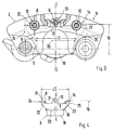
- Fig. 2
- einen Schnitt durch einen Handbremssattel mit der Reibbelageinrichtung,
- Fig. 3
- eine Ansicht in Pfeilrichtung A nach Fig. 2,
- Fig. 4
- eine Einzelheit X der Fig. 3:
Claims (9)
- Reibbelageinrichtung für einen Bremssattel, insbesondere Handbremssattel eines Kraftfahrzeugs, die wenigstens einen axial zu einer Bremsscheibe beweglichen Reibbelag umfasst, welcher Reibbelag mit Führungseinrichtungen des Bremssattels zusammenarbeitet, dadurch gekennzeichnet, dass der Reibbelag (6 und 7) durch einen kohlenstofffaserverstärkten, porösen Kohlenstoffkörper (11) gebildet wird, dessen Poren zumindest teilweise mit Silizium und Siliziumkarbid gefüllt sind, wobei der Reibbelag (6 und 7) mit Aufnahmen (12,13 und 14) für die Führungseinrichtungen (8, 9 und 10) versehen ist.
- Reibbelageinrichtung nach Anspruch I, dadurch gekennzeichnet, dass in den Kohlenstoffkörper (11) des Reibbelags (6 und 7) eine Gewebeeinlage integriert ist.
- Reibbelageinrichtung nach Anspruch 1, dadurch gekennzeichnet, dass der Reibbelag (6 und 7) einen relativ hohen Reibwert aufweist.
- Reibbelageinrichtung nach Anspruch 3, dadurch gekennzeichnet, dass der Reibbelag (6 und 7) auf seiner einer Bremsscheibe (3) zugekehrten Seite (15) mit einer Reibschicht (16) versehen ist.
- Reibbelageinrichtung nach Anspruch 1, dadurch gekennzeichnet, dass der Reibbelag (6 und 7) eine relativ hohe Temperaturbeständigkeit aufweist.
- Reibbelageinrichtung nach Anspruch 1, dadurch gekennzeichnet, dass die Aufnahmen (12, 13 und 14) des Belags (6 und 7) zumindest eine Durchgangsöffnung (21) und einen Umschlingungshaken (22,23) für die durch Bolzen gebildeten Führungseinrichtungen (8,9 und 10) aufweisen.
- Reibbelageinrichtung nach Anspruch 6, dadurch gekennzeichnet, dass in einer Vorderansicht des Reibbelags (6 und 7) gesehen die Durchgangsöffnung (21) in einer Mittellängsebene (B-B) liegt, wogegen ein erster Umschlingungshaken (22) und ein zweiter Umschlingungshaken (23) beiderseits dieser Mittellängsebene (B-B) benachbart von seitlichen Begrenzungen (25 und 26) des Belags (6 und 7) vorgesehen sind.
- Reibbelageinrichtung nach einem oder mehreren der vorangehenden Ansprüche, dadurch gekennzeichnet, dass der Reibbelag (6 und 7) durch einen Trennvorgang bspw. Wasserstrahlschneiden aus Plattenmaterial herausgearbeitet ist.
- Reibbelageinrichtung nach einem oder mehreren der vorangehenden Ansprüche, dadurch gekennzeichnet, dass sowohl die Umschlingungshaken (22 und 23) als auch die Durchgangsöffnung (21) durch den Trennvorgang gebildet werden.
Applications Claiming Priority (2)
| Application Number | Priority Date | Filing Date | Title |
|---|---|---|---|
| DE10307179 | 2003-02-20 | ||
| DE2003107179 DE10307179B4 (de) | 2003-02-20 | 2003-02-20 | Reibbelag für einen Bremssattel |
Publications (2)
| Publication Number | Publication Date |
|---|---|
| EP1450064A2 true EP1450064A2 (de) | 2004-08-25 |
| EP1450064A3 EP1450064A3 (de) | 2004-12-15 |
Family
ID=32731069
Family Applications (1)
| Application Number | Title | Priority Date | Filing Date |
|---|---|---|---|
| EP03027963A Withdrawn EP1450064A3 (de) | 2003-02-20 | 2003-12-05 | Reibbelag für einen Bremssattel |
Country Status (2)
| Country | Link |
|---|---|
| EP (1) | EP1450064A3 (de) |
| DE (1) | DE10307179B4 (de) |
Cited By (1)
| Publication number | Priority date | Publication date | Assignee | Title |
|---|---|---|---|---|
| EP1536156B1 (de) * | 2003-10-02 | 2013-09-18 | Audi Ag | Reibpaarungen für Feststellbremsen in Kraftfahrzeugen |
Citations (3)
| Publication number | Priority date | Publication date | Assignee | Title |
|---|---|---|---|---|
| DE6601232U (de) | 1967-01-27 | 1969-02-20 | Teves A Gmbh | Bremsbelagträger |
| DE6603563U (de) | 1967-01-28 | 1969-10-09 | Teves Kg Alfred | Bremsbelagtraeger |
| EP0902866B1 (de) | 1996-05-14 | 2002-08-07 | Usines Dehousse | Sinterreibbelagelement, verfahren zu seiner herstellung und verwendung bzw. für eisenbahnbremsystem |
Family Cites Families (7)
| Publication number | Priority date | Publication date | Assignee | Title |
|---|---|---|---|---|
| IT1160157B (it) * | 1983-01-10 | 1987-03-04 | Brembo Spa | Complesso di freno a disco |
| JPH043135U (de) * | 1990-04-23 | 1992-01-13 | ||
| DE19710105A1 (de) * | 1997-03-12 | 1998-09-17 | Sgl Technik Gmbh | Mit Graphitkurzfasern verstärkter Siliciumcarbidkörper |
| DE19727586C2 (de) * | 1997-06-28 | 2002-10-24 | Daimler Chrysler Ag | Bremseinheit aus Bremsscheibe und Bremsbelag |
| US5984055A (en) * | 1997-11-21 | 1999-11-16 | Northrop Grumman Corporation | Integrated fiber reinforced ceramic matrix composite brake pad and back plate |
| IT1315422B1 (it) * | 2000-04-13 | 2003-02-10 | Vittorio Pareti | Componenti frenanti particolarmente per freni di veicoli. |
| DE20019863U1 (de) * | 2000-11-23 | 2001-02-15 | Honeywell Bremsbelag GmbH, 21509 Glinde | Bremsbelag für schienen- und schienenungebundene Fahrzeuge mit einer Trägerplatte |
-
2003
- 2003-02-20 DE DE2003107179 patent/DE10307179B4/de not_active Expired - Fee Related
- 2003-12-05 EP EP03027963A patent/EP1450064A3/de not_active Withdrawn
Patent Citations (3)
| Publication number | Priority date | Publication date | Assignee | Title |
|---|---|---|---|---|
| DE6601232U (de) | 1967-01-27 | 1969-02-20 | Teves A Gmbh | Bremsbelagträger |
| DE6603563U (de) | 1967-01-28 | 1969-10-09 | Teves Kg Alfred | Bremsbelagtraeger |
| EP0902866B1 (de) | 1996-05-14 | 2002-08-07 | Usines Dehousse | Sinterreibbelagelement, verfahren zu seiner herstellung und verwendung bzw. für eisenbahnbremsystem |
Cited By (1)
| Publication number | Priority date | Publication date | Assignee | Title |
|---|---|---|---|---|
| EP1536156B1 (de) * | 2003-10-02 | 2013-09-18 | Audi Ag | Reibpaarungen für Feststellbremsen in Kraftfahrzeugen |
Also Published As
| Publication number | Publication date |
|---|---|
| DE10307179A1 (de) | 2004-09-09 |
| EP1450064A3 (de) | 2004-12-15 |
| DE10307179B4 (de) | 2007-02-08 |
Similar Documents
| Publication | Publication Date | Title |
|---|---|---|
| EP0403799B1 (de) | Bremsscheibe für Scheibenbremsen | |
| DE10060566B4 (de) | Reibkörper aus siliziuminfiltriertem, kohlenstofffaserverstärktem porösen Kohlenstoff, Verfahren zum Herstellen eines solchen Reibkörpers und Verwendung eines solchen Reibkörpers | |
| EP0104458A2 (de) | Zentrifugensieb und Verfahren zu dessen Herstellung | |
| DE69300481T2 (de) | Führungselement eines verschiebbaren sattels für scheibenbremse. | |
| EP3027927B1 (de) | Reibringkörper für eine schienenradbremse und schienenradbremse | |
| DE3544143C2 (de) | ||
| DE102020103095A1 (de) | Bremsscheibe | |
| DE19721647C2 (de) | Reibeinheit in Massivbauweise, insbesondere Bremsscheibe, mit mehreren Reibkörpern | |
| DE4332693C2 (de) | Innenbelüftete Bremsscheibe | |
| EP2153033A1 (de) | Abgasreinigungsvorrichtung für eine abgasanlage | |
| DE19954918C2 (de) | Feuerfester keramischer Gasspülstein | |
| EP3144568A1 (de) | Dichtungselement, dichtungssystem mit einem dichtungselement, turbomaschine mit einem dichtungssystem und verfahren zur herstellung eines dichtungselements | |
| EP0540566B1 (de) | Schneidwerkzeug | |
| EP1450064A2 (de) | Reibbelag für einen Bremssattel | |
| DE1525010B1 (de) | Spindelmutter und Verfahren zu ihrer Herstellung | |
| DE2166949C3 (de) | Reibklotz für eine elektromagnetisch betätigte Bremse oder Kupplung | |
| DE102018129535A1 (de) | Bauteil zum Halten oder Stützen einer Komponente | |
| DE10220016B4 (de) | Montagevorrichtung für einen Seilzug einer Feststellbremse eines Kraftfahrzeugs | |
| DE2423377A1 (de) | Bremsbacke | |
| DE69301824T2 (de) | Verbindungsvorrichtung mit elastischerrückstellung | |
| DE102007054761B4 (de) | Gasverteilerplatte für eine Heizkammer eines Ofens | |
| DE202010002330U1 (de) | Aggregatstützvorrichtung | |
| DE1576437A1 (de) | Leichtmetallzylinder mit eingegossener Laufbuechse | |
| DE2321007A1 (de) | Verfahren zum herstellen einer stumpfstossverbindung von metallstaeben und fuehrungselement zur ausfuehrung des verfahrens | |
| DE3221270C1 (de) | Kernreaktorbrennelement |
Legal Events
| Date | Code | Title | Description |
|---|---|---|---|
| PUAI | Public reference made under article 153(3) epc to a published international application that has entered the european phase |
Free format text: ORIGINAL CODE: 0009012 |
|
| AK | Designated contracting states |
Kind code of ref document: A2 Designated state(s): AT BE BG CH CY CZ DE DK EE ES FI FR GB GR HU IE IT LI LU MC NL PT RO SE SI SK TR |
|
| AX | Request for extension of the european patent |
Extension state: AL LT LV MK |
|
| PUAL | Search report despatched |
Free format text: ORIGINAL CODE: 0009013 |
|
| AK | Designated contracting states |
Kind code of ref document: A3 Designated state(s): AT BE BG CH CY CZ DE DK EE ES FI FR GB GR HU IE IT LI LU MC NL PT RO SE SI SK TR |
|
| AX | Request for extension of the european patent |
Extension state: AL LT LV MK |
|
| RIC1 | Information provided on ipc code assigned before grant |
Ipc: 7F 16D 69/02 B Ipc: 7F 16D 65/092 A |
|
| 17P | Request for examination filed |
Effective date: 20050615 |
|
| AKX | Designation fees paid |
Designated state(s): DE FR GB IT |
|
| STAA | Information on the status of an ep patent application or granted ep patent |
Free format text: STATUS: THE APPLICATION IS DEEMED TO BE WITHDRAWN |
|
| 18D | Application deemed to be withdrawn |
Effective date: 20060530 |