EP1450087A2 - Soupape électromagnétique - Google Patents
Soupape électromagnétique Download PDFInfo
- Publication number
- EP1450087A2 EP1450087A2 EP04003607A EP04003607A EP1450087A2 EP 1450087 A2 EP1450087 A2 EP 1450087A2 EP 04003607 A EP04003607 A EP 04003607A EP 04003607 A EP04003607 A EP 04003607A EP 1450087 A2 EP1450087 A2 EP 1450087A2
- Authority
- EP
- European Patent Office
- Prior art keywords
- valve
- valve according
- magnets
- valve seat
- valve housing
- Prior art date
- Legal status (The legal status is an assumption and is not a legal conclusion. Google has not performed a legal analysis and makes no representation as to the accuracy of the status listed.)
- Granted
Links
- 239000012530 fluid Substances 0.000 claims abstract description 21
- 239000003566 sealing material Substances 0.000 claims abstract description 14
- 239000000463 material Substances 0.000 claims abstract description 11
- 238000007789 sealing Methods 0.000 claims description 34
- 238000004519 manufacturing process Methods 0.000 claims description 8
- XLYOFNOQVPJJNP-UHFFFAOYSA-N water Substances O XLYOFNOQVPJJNP-UHFFFAOYSA-N 0.000 claims 1
- 238000011161 development Methods 0.000 description 6
- 230000018109 developmental process Effects 0.000 description 6
- 229920001971 elastomer Polymers 0.000 description 6
- 239000000806 elastomer Substances 0.000 description 6
- 238000005553 drilling Methods 0.000 description 4
- 239000011324 bead Substances 0.000 description 3
- 239000000853 adhesive Substances 0.000 description 1
- 230000001070 adhesive effect Effects 0.000 description 1
- 238000004873 anchoring Methods 0.000 description 1
- 238000005266 casting Methods 0.000 description 1
- 210000000078 claw Anatomy 0.000 description 1
- 230000000052 comparative effect Effects 0.000 description 1
- 230000006835 compression Effects 0.000 description 1
- 238000007906 compression Methods 0.000 description 1
- 238000010276 construction Methods 0.000 description 1
- 230000000694 effects Effects 0.000 description 1
- 230000001771 impaired effect Effects 0.000 description 1
- 238000007373 indentation Methods 0.000 description 1
- 230000005923 long-lasting effect Effects 0.000 description 1
- 238000003825 pressing Methods 0.000 description 1
- 239000012858 resilient material Substances 0.000 description 1
- 238000003860 storage Methods 0.000 description 1
- 239000000126 substance Substances 0.000 description 1
- 230000007704 transition Effects 0.000 description 1
Images



Classifications
-
- F—MECHANICAL ENGINEERING; LIGHTING; HEATING; WEAPONS; BLASTING
- F16—ENGINEERING ELEMENTS AND UNITS; GENERAL MEASURES FOR PRODUCING AND MAINTAINING EFFECTIVE FUNCTIONING OF MACHINES OR INSTALLATIONS; THERMAL INSULATION IN GENERAL
- F16K—VALVES; TAPS; COCKS; ACTUATING-FLOATS; DEVICES FOR VENTING OR AERATING
- F16K31/00—Actuating devices; Operating means; Releasing devices
- F16K31/02—Actuating devices; Operating means; Releasing devices electric; magnetic
- F16K31/06—Actuating devices; Operating means; Releasing devices electric; magnetic using a magnet, e.g. diaphragm valves, cutting off by means of a liquid
- F16K31/0644—One-way valve
- F16K31/0655—Lift valves
-
- F—MECHANICAL ENGINEERING; LIGHTING; HEATING; WEAPONS; BLASTING
- F16—ENGINEERING ELEMENTS AND UNITS; GENERAL MEASURES FOR PRODUCING AND MAINTAINING EFFECTIVE FUNCTIONING OF MACHINES OR INSTALLATIONS; THERMAL INSULATION IN GENERAL
- F16K—VALVES; TAPS; COCKS; ACTUATING-FLOATS; DEVICES FOR VENTING OR AERATING
- F16K31/00—Actuating devices; Operating means; Releasing devices
- F16K31/02—Actuating devices; Operating means; Releasing devices electric; magnetic
- F16K31/06—Actuating devices; Operating means; Releasing devices electric; magnetic using a magnet, e.g. diaphragm valves, cutting off by means of a liquid
- F16K31/0644—One-way valve
- F16K31/0651—One-way valve the fluid passing through the solenoid coil
Definitions
- the invention relates to a valve according to the preamble of Claim 1.
- Valves are diverse in the most varied Household machines used. For example Water channels in coffee machines via such valves connected.
- valves are already known in the trade become where a valve body with a sealing element is made of resilient elastomer. The valve body is moved back and forth between two pole pieces and in its respective end position held by a magnetic field.
- Valves are known from other applications which are characterized by the Use of permanent magnets are bistable, i.e. the Control coil only needs to change the switching state be pulsed with current (see e.g. DE 199 22 089).
- compliant sealing material such as one Elastomer
- the object of the invention is to provide a valve for fluid lines, especially for a household machine according to the preamble of claim 1 to propose, in which with comparative low contact pressure a long-lasting sealing function is guaranteed.
- This task is based on a valve after the Preamble of claim 1 by its characterizing Features solved.
- valve according to the invention with a at least partially within an electromagnetic Coil located valve housing and with at least two Poles made of magnetizable material provided between them an at least partially magnetic or magnetizable Valve body is arranged movably, at least one Fluid line is guided through a pole and in one annular protruding valve seat opens.
- the valve body here comprises an area made of flexible Sealing material, in particular elastomer, for sealing Form fit is provided on the valve seat.
- a valve according to the invention is now characterized characterized that outside the annular valve seat a stop surface is provided for the valve body and that between the valve seat and the stop surface Recess, preferably in the form of an annular groove, for receiving of deformed by the pressure on the valve seat Sealing material is provided.
- the stop surface for the valve body limits the path of the Valve body and thus the contact pressure with which the Sealing material is pressed onto the valve seat.
- the Indentation or the annular groove that surrounds the valve seat is provided, also allows the inclusion of sealing material deformable by the contact pressure.
- the Sealing material finds an escape space in which it can Contact pressure can evade, so that the pressure within the Material is limited.
- the sealing material can be in the valve body Insert are formed or directly in the pour the valve body into a corresponding recess become.
- the sealing material is advantageously so arranged in the valve body that it is flush with Counter stop surface of the valve body completes what the The consequence is that when the valve body stops with the Counter stop surface on the stop surface of the corresponding Pols one with the exception of the valve seat essentially closed space results, on the contour of which the resilient sealing material has to adapt.
- the assembly is designed for example due to lack of space or an equivalent Cable routing of the connections difficult.
- the assembly is therefore in a further development of the invention the valve body designed so that it is within the Coil can rotate.
- the connection of the Valve can be made much more flexible. So can for example, with the valve permanently attached to the coil Making the electrical connections can be rotated. It can also be a connection, for example by a Screwing on a fixed thread Be manufactured that the valve body with fixed Coil is rotated.
- an angled connection on Valve housing can change the connection direction by turning can be chosen arbitrarily.
- a turning aid is preferably provided, for example on the outer circumference in the form of two plane-parallel key surfaces for the approach of a Fork wrench can serve.
- valve housing at least partially rotationally symmetrical, in particular as Cylinder tube is formed.
- Cylinder tube A rotationally symmetrical
- the design simplifies the rotatable storage within the Coil, the design as a cylinder tube Using commercially available pipe pieces enables, which Manufacturing effort is significantly reduced.
- pole shoes with Fluid lines are provided.
- the pole pieces can flat, for example with a cylindrical surface on the Valve housing, created and firmly connected there, for example pressed, soldered, welded or glued become.
- the valve chamber i.e. the area between the pole pieces within which the valve body is movable is sealed, with the fluid supply or discharge through the line provided in the pole pieces are realized.
- Pole shoes designed to come out of the valve body protrude from the front. This enables the immediate Connection of the pole shoes with yoke plates or other Elements for inference of the magnetic field.
- the Pole shoes with the line connections for the fluid supply or removal.
- the direct connection of the Fluid supply or discharge to the pole shoes in turn enables it to make the valve housing shorter.
- valve housing can extend to the length of the coil can be shortened, which fixes the valve housing in axial direction possible by appropriate fixing elements is the outside of the control coil.
- this form of training is at least one yoke plate for fixing the valve housing used that at the same time for the conclusion of the magnetic field is provided.
- a yoke sheet is preferred attached to the front of the control coil to minimize as much Air gaps open for the passage of the magnetic field to let.
- a guide element outside the Valve housing provided.
- a guide element serves to do this, the valve housing inside the control coil in a radial To fix direction.
- such Guide element designed as a sleeve, so that Valve housing is guided continuously on the circumference.
- the invention Valve bistable by means of at least one permanent magnet executed so that only one control pulse for switching must take place through the control coil, the respective Switching state is also kept currentless.
- two Guide elements provided that the or Enclose permanent magnets between them.
- the magnets on the one hand on the valve housing add and on the other hand via the guide elements in the To fix inside the control coil.
- the magnets For example, designed as ring magnets, they can be in radial direction on the one hand through the valve housing as well on the other hand through the control coil and in the axial direction over the two guide sleeves through the outside, after Possibility of existing components, e.g. through a Yoke sheet to be fixed. Further fastening measures so there is no need.
- Excluding manufacturing tolerances can be a special Embodiment provided an additional compensating element become.
- Insert in particular made of flexible material, or a Adhesive material for fixing the permanent magnets. That too Introducing curable casting material can be used as compensation be used for manufacturing tolerances to the Permanent magnets reliable even with the switching operations of the To fix the valve.
- the Permanent magnets made of deformable material, so that they can be joined together under pressure.
- plastic-bound ones Permanent magnets that are already commercially available.
- magnets Another way to get a magnetic movement during the Suppress switching, is the magnets to be provided with deformable projections which are inserted and compression by outer guide sleeves Clamp the magnets firmly.
- Valve In addition to use in household machines, such as Coffee machines or the like is an inventive Valve also in other areas, e.g. in the field of Analytics or in general in the field of pharmaceutical and chemical plants can be used.
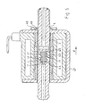
- the valve 1 according to FIG. 1 comprises a control coil 2, in whose interior is a valve housing 3 in the form of a Pipe piece is located.
- a valve housing 3 in the form of a Pipe piece is located.
- Valve housing 3 connected, for example soldered, pressed, welded, glued, etc.
- the valve housing 3 ends flush with the control coil 2.
- valve housing 3 is rotatable inside the control coil 2 stored.
- a valve body 13 is in the direction of the double arrow P. slidable in the through the pole pieces 4, 5 and that Valve housing 3 formed valve chamber 14 is arranged.
- the Valve body 13 comprises a sealing element 15, which in a poured corresponding recess of the valve body 13 is.
- On the free side 16 of the valve body 13 is recognizable that the sealing element 15 is flush with the Valve body 13 ends.
- the sealing element On the opposite side is the sealing element is designed accordingly in the present position, however, as described below is deformed.
- a fluid line 18 opens into the sealing seat 17, to which in turn an outside line is connected can be.
- a hose is the protruding area of the pole piece 5 as a hose nozzle 19 educated. A hose can be pushed over the bead 20 and in the cylindrical region 21 behind the bead 20 ' be clamped using a clamping ring.
- the pole piece 4 also comprises a fluid line 22 which is shown in FIG axial direction and in a right angle to it standing bore 23 opens.
- This bore 23 serves the Flow in the direction of the inner circumference of the valve housing 3 steer since there outside the valve body 13 in the axial Direction the flow through the valve chamber 14 takes place.
- the Valve body 13 is not directly on the face flowed so that its mobility through the Fluid flow is less affected.
- the arrangement of the holes at right angles to each other 22, 23, which are easily drilled from the outside into the pole piece 4 can is particularly advantageous for production.
- the pole piece 5 is shown in the enlarged view Figure 2 can be seen more clearly.
- the sealing seat 17 is in shape an annular projection formed. Inside the sealing seat 17 this passes into the wall 25 of the bore 26, through which opens the fluid line 18 at the valve seat 17. Outside of the valve seat 17, a stop surface 27 is provided which the valve body 13 can strike.
- valve seat 17 and Stop surface 27 are in the enlargement according to FIG Shown individually.
- the annular valve seat 17 moves along a radius 28 into the wall 25 of the bore 26.
- a bevel 29 is attached, which over the Height of the stop surface 27 in an annular groove 30th transforms.
- the annular groove 30 is of crucial importance.
- the sealing element 15 deforms accordingly from resilient material, for example an elastomer. In the area of the bore 26 can the material therefore hugs the radius 28 and inside avoid the bore 26.
- the material lies on the Bevel 29 and dips into the annular groove 30.
- the Ring groove 30 is dimensioned so that it displaces the Material through the projecting valve seat 17 at least partially compensated. Through this compensation volume the pressure inside the sealing element 15, which by the Contact pressure of the valve body 13 on the stop surface 27 is caused. Despite this reduction in pressure acting on the sealing material is reliable sealing form fit between the sealing element 15 and the Valve seat 17 ensures, however, the wear is significantly reduced.
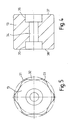
- the valve body itself is, as shown in FIG. 5 recognizable, rotationally symmetrical with equally distributed ribs 31 and intermediate channels 32.
- ribs 31 is a guide on the inside of the valve housing 3 ensures free flow through channels 32 of the fluid is guaranteed.
- This structure enables the outside flow around the valve body, so that inner Fluid guides are not required, while the Guide surface of the valve body 13 on the contact surfaces 33 the ribs 31 is reduced, whereby the friction in the Movement of the valve body 13 is significantly reduced.
- a bore 34 in the interior of the valve body 13 with end widenings 35, 36 serve to accommodate the Sealing element 15.
- the sealing element 15 is in the bore 34th inserted, for example, poured in so that it is flush ends with the end faces 37, 38 of the valve body 13.
- valve body 13 This is formed by the widenings 35, 36 Sealing element fixed in the axial direction in the valve body 13. Due to the symmetrical structure, a such valve body 13 can also be used in valves, in which a valve seat on both sides of the valve body 13 attached and accordingly a sealing function on both sides of the valve body 13 is required.
- annular groove 30 which in the illustration according to FIG. 1 only because of the small dimensions as clearly as can be seen in FIG. 5, are unnecessary in Connection to the stop surface 27 complex measures such as a spring bearing or the like, to limit the contact pressure around the sealing element 15 to protect.
- valve housing 3 together with the pole pieces 4, 5 rotatably mounted inside the control coil, whereby the Assembly of the valve 1 is considerably simplified.
- the positive arrangement of the guide sleeves 6, 7 and Magnets 8, 9 also ensures an extreme quiet operation.
- FIGS. 6 and 7 differs different design of the valve body 39.
- Die central bore 40 is in this embodiment in Ratio to the total diameter of the valve body 39 wider executed.
- the punctures 41, 42 are arranged in the vicinity of the end faces 44, 45.
- a valve according to the invention is extremely small Assemble number of different parts so that the Overall production with significantly reduced effort compared to previous valves.
Landscapes
- Engineering & Computer Science (AREA)
- General Engineering & Computer Science (AREA)
- Mechanical Engineering (AREA)
- Magnetically Actuated Valves (AREA)
- Lift Valve (AREA)
Priority Applications (1)
| Application Number | Priority Date | Filing Date | Title |
|---|---|---|---|
| CA002497243A CA2497243C (fr) | 2004-02-18 | 2005-02-14 | Methode, systeme et application logicielle permettant le traitement des donnees en temps reel |
Applications Claiming Priority (2)
| Application Number | Priority Date | Filing Date | Title |
|---|---|---|---|
| DE2003107060 DE10307060A1 (de) | 2003-02-19 | 2003-02-19 | Ventil |
| DE10307060 | 2003-02-19 |
Publications (3)
| Publication Number | Publication Date |
|---|---|
| EP1450087A2 true EP1450087A2 (fr) | 2004-08-25 |
| EP1450087A3 EP1450087A3 (fr) | 2005-03-30 |
| EP1450087B1 EP1450087B1 (fr) | 2007-12-05 |
Family
ID=32731053
Family Applications (1)
| Application Number | Title | Priority Date | Filing Date |
|---|---|---|---|
| EP20040003607 Expired - Lifetime EP1450087B1 (fr) | 2003-02-19 | 2004-02-18 | Soupape électromagnétique |
Country Status (2)
| Country | Link |
|---|---|
| EP (1) | EP1450087B1 (fr) |
| DE (2) | DE10307060A1 (fr) |
Families Citing this family (4)
| Publication number | Priority date | Publication date | Assignee | Title |
|---|---|---|---|---|
| DE102005061509B4 (de) * | 2005-05-06 | 2014-08-07 | Continental Teves Ag & Co. Ohg | Elektromagnetventil |
| EP2716946B1 (fr) | 2012-10-02 | 2014-09-17 | FESTO AG & Co. KG | Dispositif de soupape et son procédé de fabrication |
| DE102012220140B4 (de) * | 2012-11-06 | 2021-06-02 | Kuhnke Automotive Gmbh & Co. Kg | Ankerkörper für ein Ventil, insbesondere Pneumatikventil |
| US10571041B2 (en) | 2015-08-28 | 2020-02-25 | Taylor Commercial Foodservice Inc. | Bi-stable changeover valve |
Citations (1)
| Publication number | Priority date | Publication date | Assignee | Title |
|---|---|---|---|---|
| DE19922089A1 (de) | 1999-05-17 | 2000-11-23 | Schrott Harald | Bistabiles elektromagnetisches Ventil |
Family Cites Families (6)
| Publication number | Priority date | Publication date | Assignee | Title |
|---|---|---|---|---|
| GB686658A (en) * | 1951-03-06 | 1953-01-28 | Skinner Chuck Company | Improvements in valve construction |
| GB1417669A (en) * | 1972-11-02 | 1975-12-10 | Fluid Devices Ltd | Bistable electromagnetically-actuated valve |
| DE4117958C2 (de) * | 1991-05-31 | 2000-05-11 | Bosch Gmbh Robert | Magnetventil |
| DE19516885C1 (de) * | 1995-05-09 | 1996-10-24 | Elektroteile Gmbh | Pneumatikventil |
| WO2000017554A1 (fr) * | 1998-09-17 | 2000-03-30 | Schrott, Harald | Circuit de production de froid pour installation refrigerante |
| DE19922466C2 (de) * | 1999-05-17 | 2002-06-13 | Schrott Harald | Verfahren zur Herstellung eines elektromagnetischen Ventils |
-
2003
- 2003-02-19 DE DE2003107060 patent/DE10307060A1/de not_active Withdrawn
-
2004
- 2004-02-18 DE DE200450005632 patent/DE502004005632D1/de not_active Expired - Lifetime
- 2004-02-18 EP EP20040003607 patent/EP1450087B1/fr not_active Expired - Lifetime
Patent Citations (1)
| Publication number | Priority date | Publication date | Assignee | Title |
|---|---|---|---|---|
| DE19922089A1 (de) | 1999-05-17 | 2000-11-23 | Schrott Harald | Bistabiles elektromagnetisches Ventil |
Also Published As
| Publication number | Publication date |
|---|---|
| EP1450087B1 (fr) | 2007-12-05 |
| DE10307060A1 (de) | 2004-09-16 |
| DE502004005632D1 (de) | 2008-01-17 |
| EP1450087A3 (fr) | 2005-03-30 |
Similar Documents
| Publication | Publication Date | Title |
|---|---|---|
| DE102005035798B4 (de) | Elektromagnetventil | |
| DE102013200533B4 (de) | Ventilpatrone | |
| DE102010011562A1 (de) | Absperrelement für fluide Medien, Rückschlagklappe mit einem Absperrelement sowie Baueinheit hieraus | |
| DE102009043320B4 (de) | Elektrohydraulisches Ventil | |
| DE4036491A1 (de) | Magnetventil | |
| DE102007005916A1 (de) | Doppelankermagnetventil mit zwei Ventilöffnungen und mindestens einem die Ventilöffnungen verbindenden Kanal | |
| EP2581920B1 (fr) | Electroaimant | |
| DE102008063339A1 (de) | Ventil | |
| WO2003071175A1 (fr) | Soupape electromagnetique | |
| EP1450087B1 (fr) | Soupape électromagnétique | |
| EP0214394B2 (fr) | Pompe à diaphragme | |
| EP1936248A2 (fr) | Ventilateur électromagnétique pour milieux liquides et gazeux | |
| DE102013017259B4 (de) | Ventil | |
| DE102008018066A1 (de) | Treibstoffeinspritzventil und Verfahren zum Herstellen von diesem | |
| DE10307059A1 (de) | Ventil | |
| DE102005056039B4 (de) | Hydraulisches / pneumatisches Steuerventil mit Fail-Safe Funktion | |
| DE102009025576A1 (de) | Absperrelement für fluide Medien, Rückschlagklappe mit einem Absperrelement sowie Baueinheit hieraus | |
| DE102009060031A1 (de) | Magnetventil | |
| EP2278199B1 (fr) | Soupape d'arrêt améliorée | |
| DE112014006155B4 (de) | Ventil mit variablem Durchfluss und Verfahren zum Herstellen eines Ventils mit variablem Durchfluss | |
| DE102017107844A1 (de) | Kugelhahn, Verfahren zum Herstellen sowie zum Zusammenbau eines derartigen Kugelhahns | |
| WO2007045535A1 (fr) | Soupape electromagnetique | |
| DE202013009183U1 (de) | Ventil | |
| DE102019200940A1 (de) | Schnellschaltventil | |
| DE102004038090B4 (de) | Magnetventil |
Legal Events
| Date | Code | Title | Description |
|---|---|---|---|
| PUAI | Public reference made under article 153(3) epc to a published international application that has entered the european phase |
Free format text: ORIGINAL CODE: 0009012 |
|
| AK | Designated contracting states |
Kind code of ref document: A2 Designated state(s): AT BE BG CH CY CZ DE DK EE ES FI FR GB GR HU IE IT LI LU MC NL PT RO SE SI SK TR |
|
| AX | Request for extension of the european patent |
Extension state: AL LT LV MK |
|
| PUAL | Search report despatched |
Free format text: ORIGINAL CODE: 0009013 |
|
| AK | Designated contracting states |
Kind code of ref document: A3 Designated state(s): AT BE BG CH CY CZ DE DK EE ES FI FR GB GR HU IE IT LI LU MC NL PT RO SE SI SK TR |
|
| AX | Request for extension of the european patent |
Extension state: AL LT LV MK |
|
| 17P | Request for examination filed |
Effective date: 20050915 |
|
| AKX | Designation fees paid |
Designated state(s): CH DE FR GB IT LI TR |
|
| GRAP | Despatch of communication of intention to grant a patent |
Free format text: ORIGINAL CODE: EPIDOSNIGR1 |
|
| GRAS | Grant fee paid |
Free format text: ORIGINAL CODE: EPIDOSNIGR3 |
|
| GRAA | (expected) grant |
Free format text: ORIGINAL CODE: 0009210 |
|
| AK | Designated contracting states |
Kind code of ref document: B1 Designated state(s): CH DE FR GB IT LI TR |
|
| REG | Reference to a national code |
Ref country code: GB Ref legal event code: FG4D Free format text: NOT ENGLISH |
|
| REG | Reference to a national code |
Ref country code: CH Ref legal event code: EP |
|
| REF | Corresponds to: |
Ref document number: 502004005632 Country of ref document: DE Date of ref document: 20080117 Kind code of ref document: P |
|
| GBV | Gb: ep patent (uk) treated as always having been void in accordance with gb section 77(7)/1977 [no translation filed] | ||
| REG | Reference to a national code |
Ref country code: CH Ref legal event code: PL |
|
| EN | Fr: translation not filed | ||
| PLBE | No opposition filed within time limit |
Free format text: ORIGINAL CODE: 0009261 |
|
| STAA | Information on the status of an ep patent application or granted ep patent |
Free format text: STATUS: NO OPPOSITION FILED WITHIN TIME LIMIT |
|
| PG25 | Lapsed in a contracting state [announced via postgrant information from national office to epo] |
Ref country code: CH Free format text: LAPSE BECAUSE OF NON-PAYMENT OF DUE FEES Effective date: 20080229 Ref country code: LI Free format text: LAPSE BECAUSE OF NON-PAYMENT OF DUE FEES Effective date: 20080229 |
|
| 26N | No opposition filed |
Effective date: 20080908 |
|
| PG25 | Lapsed in a contracting state [announced via postgrant information from national office to epo] |
Ref country code: GB Free format text: LAPSE BECAUSE OF FAILURE TO SUBMIT A TRANSLATION OF THE DESCRIPTION OR TO PAY THE FEE WITHIN THE PRESCRIBED TIME-LIMIT Effective date: 20071205 |
|
| PG25 | Lapsed in a contracting state [announced via postgrant information from national office to epo] |
Ref country code: FR Free format text: LAPSE BECAUSE OF FAILURE TO SUBMIT A TRANSLATION OF THE DESCRIPTION OR TO PAY THE FEE WITHIN THE PRESCRIBED TIME-LIMIT Effective date: 20081003 |
|
| PGFP | Annual fee paid to national office [announced via postgrant information from national office to epo] |
Ref country code: IT Payment date: 20100220 Year of fee payment: 7 |
|
| PGFP | Annual fee paid to national office [announced via postgrant information from national office to epo] |
Ref country code: TR Payment date: 20100216 Year of fee payment: 7 |
|
| PG25 | Lapsed in a contracting state [announced via postgrant information from national office to epo] |
Ref country code: IT Free format text: LAPSE BECAUSE OF NON-PAYMENT OF DUE FEES Effective date: 20110218 |
|
| REG | Reference to a national code |
Ref country code: DE Ref legal event code: R082 Ref document number: 502004005632 Country of ref document: DE Representative=s name: VON KREISLER SELTING WERNER, DE |
|
| REG | Reference to a national code |
Ref country code: DE Ref legal event code: R081 Ref document number: 502004005632 Country of ref document: DE Owner name: ZHEJIANG SANHUA INTELLIGENT CONTROLS CO., LTD., CN Free format text: FORMER OWNER: AWECO APPLIANCE SYSTEMS GMBH & CO. KG, 88099 NEUKIRCH, DE Effective date: 20120627 Ref country code: DE Ref legal event code: R082 Ref document number: 502004005632 Country of ref document: DE Representative=s name: VON KREISLER SELTING WERNER - PARTNERSCHAFT VO, DE Effective date: 20120627 Ref country code: DE Ref legal event code: R081 Ref document number: 502004005632 Country of ref document: DE Owner name: ZHEJIANG SANHUA CO., LTD., CHENGGUAN TOWN, CN Free format text: FORMER OWNER: AWECO APPLIANCE SYSTEMS GMBH & CO. KG, 88099 NEUKIRCH, DE Effective date: 20120627 Ref country code: DE Ref legal event code: R081 Ref document number: 502004005632 Country of ref document: DE Owner name: ZHEJIANG SANHUA CO., LTD., CN Free format text: FORMER OWNER: AWECO APPLIANCE SYSTEMS GMBH & CO. KG, 88099 NEUKIRCH, DE Effective date: 20120627 Ref country code: DE Ref legal event code: R082 Ref document number: 502004005632 Country of ref document: DE Representative=s name: DOMPATENT VON KREISLER SELTING WERNER - PARTNE, DE Effective date: 20120627 |
|
| PG25 | Lapsed in a contracting state [announced via postgrant information from national office to epo] |
Ref country code: TR Free format text: LAPSE BECAUSE OF NON-PAYMENT OF DUE FEES Effective date: 20110218 |
|
| REG | Reference to a national code |
Ref country code: DE Ref legal event code: R082 Ref document number: 502004005632 Country of ref document: DE Representative=s name: DOMPATENT VON KREISLER SELTING WERNER - PARTNE, DE Ref country code: DE Ref legal event code: R081 Ref document number: 502004005632 Country of ref document: DE Owner name: ZHEJIANG SANHUA INTELLIGENT CONTROLS CO., LTD., CN Free format text: FORMER OWNER: ZHEJIANG SANHUA CO., LTD., CHENGGUAN TOWN, XINCHANG COUNTY, CN |
|
| PGFP | Annual fee paid to national office [announced via postgrant information from national office to epo] |
Ref country code: DE Payment date: 20230207 Year of fee payment: 20 |
|
| REG | Reference to a national code |
Ref country code: DE Ref legal event code: R071 Ref document number: 502004005632 Country of ref document: DE |