EP1450101B1 - Endrohr für ein kombiniertes Luft-Abgasrohr - Google Patents
Endrohr für ein kombiniertes Luft-Abgasrohr Download PDFInfo
- Publication number
- EP1450101B1 EP1450101B1 EP04290369A EP04290369A EP1450101B1 EP 1450101 B1 EP1450101 B1 EP 1450101B1 EP 04290369 A EP04290369 A EP 04290369A EP 04290369 A EP04290369 A EP 04290369A EP 1450101 B1 EP1450101 B1 EP 1450101B1
- Authority
- EP
- European Patent Office
- Prior art keywords
- wall
- cap
- tube
- unit
- periphery
- Prior art date
- Legal status (The legal status is an assumption and is not a legal conclusion. Google has not performed a legal analysis and makes no representation as to the accuracy of the status listed.)
- Expired - Lifetime
Links
Images


Classifications
-
- F—MECHANICAL ENGINEERING; LIGHTING; HEATING; WEAPONS; BLASTING
- F23—COMBUSTION APPARATUS; COMBUSTION PROCESSES
- F23L—SUPPLYING AIR OR NON-COMBUSTIBLE LIQUIDS OR GASES TO COMBUSTION APPARATUS IN GENERAL ; VALVES OR DAMPERS SPECIALLY ADAPTED FOR CONTROLLING AIR SUPPLY OR DRAUGHT IN COMBUSTION APPARATUS; INDUCING DRAUGHT IN COMBUSTION APPARATUS; TOPS FOR CHIMNEYS OR VENTILATING SHAFTS; TERMINALS FOR FLUES
- F23L17/00—Inducing draught; Tops for chimneys or ventilating shafts; Terminals for flues
- F23L17/02—Tops for chimneys or ventilating shafts; Terminals for flues
- F23L17/12—Devices for fastening the top or terminal to chimney, shaft, or flue
-
- F—MECHANICAL ENGINEERING; LIGHTING; HEATING; WEAPONS; BLASTING
- F23—COMBUSTION APPARATUS; COMBUSTION PROCESSES
- F23J—REMOVAL OR TREATMENT OF COMBUSTION PRODUCTS OR COMBUSTION RESIDUES; FLUES
- F23J13/00—Fittings for chimneys or flues
- F23J13/04—Joints; Connections
-
- F—MECHANICAL ENGINEERING; LIGHTING; HEATING; WEAPONS; BLASTING
- F23—COMBUSTION APPARATUS; COMBUSTION PROCESSES
- F23L—SUPPLYING AIR OR NON-COMBUSTIBLE LIQUIDS OR GASES TO COMBUSTION APPARATUS IN GENERAL ; VALVES OR DAMPERS SPECIALLY ADAPTED FOR CONTROLLING AIR SUPPLY OR DRAUGHT IN COMBUSTION APPARATUS; INDUCING DRAUGHT IN COMBUSTION APPARATUS; TOPS FOR CHIMNEYS OR VENTILATING SHAFTS; TERMINALS FOR FLUES
- F23L17/00—Inducing draught; Tops for chimneys or ventilating shafts; Terminals for flues
- F23L17/02—Tops for chimneys or ventilating shafts; Terminals for flues
- F23L17/04—Balanced-flue arrangements, i.e. devices which combine air inlet to combustion unit with smoke outlet
-
- F—MECHANICAL ENGINEERING; LIGHTING; HEATING; WEAPONS; BLASTING
- F23—COMBUSTION APPARATUS; COMBUSTION PROCESSES
- F23J—REMOVAL OR TREATMENT OF COMBUSTION PRODUCTS OR COMBUSTION RESIDUES; FLUES
- F23J2213/00—Chimneys or flues
- F23J2213/40—Heat insulation fittings
Definitions
- the present invention relates to a termination device for double-walled smoke duct.
- a double-walled smoke duct is intended to evacuate the combustion gases, on the one hand, and to supply combustion air, on the other hand, one or more heaters said to sealed combustion, liquid or gaseous fuel.
- a so-called sealed combustion heater does not take air in its direct environment but away from where it is installed.
- the air is usually collected near the place, for example the exterior of a building, where the smoke produced by the combustion can be evacuated. That is why it has been proposed, in the case of heaters with remote combustion air source to use a double-wall pipe with concentric pipes in which an inner pipe conveys the fumes to be evacuated and an outer pipe vehicle the combustion air to the heater using the annular space between the walls of the inner pipe and the outer pipe.
- Existing double-walled flues are designed so that a termination part, for example, is on the roof of a roof. building extends vertically, the inner pipe opening upwards to allow the evacuation of combustion gases.
- the outer pipe also opens upwards, but its opening is below the opening of the outer pipe, so that the annular space forming the air inlet mouth is below the opening of the inner pipe.
- a flue gas outlet forming a flue gas outlet.
- the flue generally comprises a protective cap installed above the opening of the inner pipe, so as to protect this opening while allowing the evacuation of combustion gases. Such a device is described by the document US Patent 3376834 -AT.
- the flue may also include a bell attached to the top of the outer pipe opening so that air drawn through the annular opening between the inner pipe and the outer pipe enters from below the bell.
- a first problem with known double-walled flue pipes is that the flue gas discharged upwards through the opening of the inner pipe can nevertheless mix with the aspirated combustion gas. This mixing can occur even if the oxidizing gas is sucked under a bell.
- a second problem with known double-walled flue pipes is that the moisture in the relatively hot gases discharged from the inner pipe can condense and freeze when these gases are suddenly cooled to the outside.
- a pile of ice may form on the pipe.
- Such a pile of ice can, on the one hand, interfere with the operation of the duct, for example by preventing the arrival of air in the duct, and, on the other hand, create other problems such as falling ice.
- the present invention particularly relates to a double-walled smoke duct to solve the problems just mentioned.
- the present invention relates to a double-walled smoke duct termination device for a heating appliance, said flue comprising an inner pipe conveying the flue gases to be discharged and an outer pipe conveying the combustion air to the heating appliance using the annular space between the walls of the inner pipe and the outer pipe, characterized in that said termination device comprises a concentric inner pipe and a concentric outer pipe, respectively extending said inner pipe and said outer pipe of said pipe, in that said pipe interior opens upwards so that its upper end forms the average outlet smoke, in that said outer pipe surrounds said inner pipe over substantially the entire height of the latter, and that combustion air inlet means is provided on the periphery of said outer pipe at a height such that said air inlet means is below and away from said flue outlet means.
- the outer pipe continues to surround the inner pipe above the air inlet means to the smoke outlet means, the annular space between the walls of these pipes can serve as an insulating compartment. for thermally isolating the inner duct from the outside air and is filled with a thermal insulator in a zone starting above said combustion air inlet means and up to its upper end.
- a first bell member obstructs the annular space between said inner and outer pipes at the upper end of said outer pipe.
- a ring is obstructing the annular space between said inner and outer pipes above said combustion air inlet means.
- This crown or sealing ring makes it possible to direct the flow of air downwards and to prevent upwelling.
- said first bell-shaped element is fixed by interlocking with said inner pipe.
- said first bell-shaped element is fixed by simultaneous crimping of its wall and the wall of said inner pipe.
- said air inlet means consists of a plurality of holes formed on the periphery of said outer pipe.
- a second bell-shaped element is fixed by its upper part to the periphery of said outer pipe, just above said air inlet means, so that said second bell-shaped element extends around the outer pipe in look at said air inlet means.
- said second bell-shaped element is fitted on said outer pipe.
- said second bell-shaped element is fixed by simultaneous crimping of its wall and the wall of said outer pipe.
- said smoke outlet means is surmounted by an anti-reflector cap means comprising a ferrule surrounding said smoke outlet means and a helmet disposed above said ferrule so that the smoke escapes between the upper end of said shell and the periphery of said helmet.
- said helmet comprises a bottom wall of frustoconical shape tapering down which is opposite said smoke outlet means.
- a frustoconical wall tapered upwardly is formed around the upper part of said inner tube, the angle of inclination of said wall being opposite to the angle of inclination of said frustoconical lower wall of said helmet .
- said helmet consists of an upper wall and a lower wall, an empty compartment or filled with a thermal insulator being formed between these two walls.
- This insulating compartment helps to prevent the formation of condensation under the helmet of the hat.
- said helmet is of a size such that the periphery of said helmet constitutes the part of said termination device farthest from the axis of said termination device.
- condensation droplets that may possibly form at the periphery of the helmet or drops of water from the rainwater falling on the top of the helmet are sufficiently far from the areas that should be protected from a possible ice formation.
- the present invention is applicable to a double-walled flue for a combustion heater having a remote combustion air source.
- a duct comprises an inner pipe conveying the fumes to the exterior of a building, the air intended to supply the heating apparatus flowing from the outside of the building to the heating apparatus, in the annular space created between the inner pipe and the outer pipe.
- a conduit consists of several conduit elements placed end to end.
- the present invention relates to the terminal conduit element, a part provided with smoke outlet means and combustion air inlet is located outside the building.
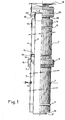
- a terminal pipe element 1 generally comprises an inner pipe 2 open at its upper end forming a smoke outlet means 3, a coaxial outer pipe 4 provided with an air inlet means 5 located in a zone of air intake located at a distance below the smoke outlet zone, a bell 6 fixed to the periphery of the outer pipe 4 at the air inlet zone, a bell 16 fixed to the periphery of the inner pipe for closing from above the gap between the inner and outer pipes, and an assembly 8 covering the smoke outlet zone forming an anti-reflector cap consisting of a shell 33 surmounted by a helmet 35.
- the inner pipe 2 and outer pipe 4 are each of generally circular cylindrical shape.
- the outer pipe 4 is of a diameter greater than the diameter of the inner pipe 2 so as to leave an annular space 9 between the inner pipe 2 and the outer pipe 4 sufficient to allow the supply of combustion air to the heating device .
- the inner pipe 2 is longer than the outer pipe 4 and exceeds the latter in the lower part of the terminal pipe element 1 which facilitates the fitting of the latter on the flue.
- This inner pipe 2 comprises at its lower end a reentrant edge 21.
- the upper end of the inner pipe 2 opening towards the top forms the outlet zone of the fumes 3.
- the outer pipe 4 has at its lower end a reentrant edge 10 above which is formed a ring 11 projecting outwardly.
- This ring 11 is intended to serve as a support which carries the upper end of the outer pipe of the flue, the portion between the rod 11 and the re-entrant edge 10 being adapted to fit into this outer pipe of the smoke duct.
- Two nut fixing means 7 set at the same height, opposite diametrically, on the pipe 4 allow the attachment of the terminal duct element 1 to a roof flashing 45, as can be seen on the Fig. 5 .
- a combustion air inlet means 5 is constituted by a plurality of holes formed at the periphery of the outer pipe 4. This set of peripheral holes defines an air inlet or air intake means 5 which is located at a distance from the upper end of the end duct element 1. This distance is provided for the air inlet zone 5 to be as far as possible from the smoke outlet zone 3. As well as we see it well on the Fig. 5 when the terminal duct element 1 is mounted on the roof of a building, passing through a frustoconical skirt 48 of a roof flashing 45, the air inlet zone 5 is close to the upper end. of the frustoconical skirt 48, in the lowest possible position allowing an intake of outside air.
- This ring 12 has two functions. First, it is used for crimping the bell 6 on the outer pipe 4 as will be seen later. Then, it serves to support a ring 19 for sealing the annular space 9 above the combustion air inlet means 5.
- a ring protruding outwards serving as a support for the bell 16 adapted to obstruct the annular space 9 between the inner and outer pipes above the outer pipe.
- the annular space 9 between the inner and outer pipes is filled with a thermal insulator in the area between the ring 19 and the upper end of the outer pipe 4 covered by the bell 16.
- the bell 6 comprises at its top a first cylindrical portion of diameter slightly greater than the diameter of the outer pipe 4 so as to allow the bell to fit on the latter and then, downwards, a frustoconical flare 14 and a second cylindrical portion 15 on which is formed an inwardly recessed rod to prevent the intrusion of volatiles in the air inlet means and to stiffen the bell at its lower end.
- the upper cylindrical portion allows, as described below, the attachment of the bell to the periphery of the outer pipe, just above the air inlet zone, so that the second cylindrical portion 15 s extends around the outer pipe facing the air inlet holes 5, at a distance sufficient to allow the passage of air from below the bell.
- the fixing of the bell 6 on the outer pipe is done by interlocking the outer pipe 4 in the bell 6 so that the outer wall of the pipe is pressed against the inner surface of the upper cylindrical part of the bell, and then by crimping this cylindrical part in the rod 12.
- the crimping is conducted by means of a tube crimping device adapted to surround the pipe.
- the bell 16 comprises at its top a first cylindrical portion 20 of diameter slightly greater than the diameter of the inner pipe 2 so as to allow the bell to fit on the latter, then, downwards, a frustoconical flare 18 and then a second cylindrical portion 17 which bears on the rod 13 of the outer pipe.
- the upward inclination of the wall 18 contributes to improving the aerodynamic performance of the anti-reflector cap.
- the fixing of the bell 16 on the inner pipe is done by interlocking the inner pipe 2 in the bell 16 so that the outer wall of the pipe is pressed against the inner surface of the cylindrical portion 20, and then by expansion of the inner pipe.
- the expansion is carried out by means of a tube expansion device which is introduced into the pipe.
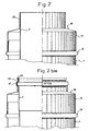
- the Fig. 2 shows the assembly of the inner pipe and the bell before expansion and the Fig. 2a shows this assembly after expansion.
- the inner pipe 2 comprises from top to bottom a first outwardly flared edge 25 and then a cylindrical portion 26 of larger diameter than the same before expansion portion and then an outwardly projecting portion forming a throat trapezoidal 27.
- the deformation of the inner pipe 2 causes a corresponding deformation of the cylindrical portion 20 of the bell 16, so that a mechanical key is formed between the inner pipe 2 and the bell 16 for fixing the latter.
- this cap generally comprises a fixing cylinder 28, a ferrule 33 surrounding the smoke outlet zone and a cap helmet 35 disposed above said ferrule so that smoke escapes between the upper end of the ferrule. said ferrule and the periphery of said helmet, the assembly being kept coherent by means of connecting lugs 32 welded to these different elements.
- the cylinder 28 has a diameter substantially smaller than the diameter of the upper part of the inner pipe 2 after expansion which allows the cylinder to fit into this pipe. It is of course open, extending in practice the inner pipe 2 so as to let out the fumes at its upper end.
- the lower end of the cylinder 28 is provided with an inwardly-inward rim 29 while at the upper end of this cylinder is provided an outwardly projecting rod 30 for bearing on the flared edge. 25 of the upper end of the inner pipe 2.
- a snap fastening lug 24 is provided on the cylinder 28, this lug being intended to engage with the trapezoidal groove 27 of the inner pipe 2.
- the rod 30 support on the flared edge 25 and the lug 24 in engagement with the trapezoidal groove 27 constitute a mechanical key immobilizing the anti-reflector cap on the inner pipe.
- To dismantle the anti-recoating cap it is necessary to push the tab 24 which is possible by means of an elongated object such as a screwdriver inserted through a bore 23 provided for this purpose on the upper part of the bell 16, at the level of the trapezoidal groove 27, as can be seen on the Fig. 2a .
- the shell 33 is of cylindrical shape and extends along the axis of the assembly of the end duct element 1. It is of a diameter slightly greater than the outside diameter of the bell 16 and therefore the diameter of the pipe 4.
- Rods 42 are formed at a lower portion and an upper portion of the ferrule 33. These rods project outwardly.
- the shell 33 surrounds the flue outlet, the upper end of the cylinder 28 being between the two rods 42, slightly closer to the lower ring.
- the connecting lugs 32, coming from the cylinder 28, go up along the inner wall of the shell to which they are welded.
- This ferrule forms the body of the anti-painter hat. It is intended in particular to protect the exit of smoke from gusts of wind and rain inputs in the inner pipe 2.
- the helmet 35 is composed of a lower part and an upper part assembled by spot welding.
- the lower piece 34 comprises, from the center to the periphery, a horizontal flat 39, a frustoconical portion 38 inclined upwards and, at the periphery, a flat edge 37 slightly inclined downwards forming a drop of water.
- the upper piece 36 is a disc whose periphery follows the descending edge of the lower piece 34.
- the frustoconical portion 38 describes an angle identical to that described by the frustoconical portion 18 of the bell 16 in the opposite direction.
- a compartment 40 empty or filled with a thermal insulator helps to prevent the formation of condensation under the helmet of the hat.
- the helmet 35 is held above the shell 33 by means of the tabs 32 welded to the periphery of the frustoconical portion 38.
- the diameter of this helmet is greater than the diameter of the bell 6 so as to move away from the entire body. End duct element the rainwater falling on the top piece of this helmet.
- Fig. 2a and Fig.3 are represented in an assembled manner at the Fig. 4 .
- the flared edge 25 comes into contact with the ring 30 and that the tab 24 is eclipsed in the trapezoidal groove 27.
- the shell 33 is firmly connected to the bell 16.
- a waterproof roof penetration system 44 comprises a roof flashing 45 formed of a base plate 46 equipped with a flexible or malleable flap 47 at its lower part and a frustoconical skirt 48 welded to the base plate. 46, a rod 52 recessed inward and two tabs 49 facing each other on either side of the upper part of the frustoconical skirt, these legs being pierced each of an orifice 50.
- the orifices 50 allow the fastening by screwing of the terminal conduit element 1 by means of the nuts 7 of this element 1.
- This fastening system allows an angular adjustment according to the different slopes of the roof, the final blocking of the element duct being ensured during the nesting of the lower duct elements.
- the angular adjustment of the flashing 45 is effected by pivoting the frustoconical skirt 48 around the axis of the orifice 50 which is situated in a plane parallel to that of the roof and in a direction perpendicular to the direction of the roof's greater slope. .
- the flashing 45 takes place on the roof in an adjusted manner.
- a watertight teardrop 51 is clamped on the body of the terminal duct element between the flashing 45 and the air intake bell 6. This drip beam 51 avoids the entry of water. water or volatiles inside the flashing 45.
Landscapes
- Engineering & Computer Science (AREA)
- Mechanical Engineering (AREA)
- General Engineering & Computer Science (AREA)
- Chemical & Material Sciences (AREA)
- Combustion & Propulsion (AREA)
- Exhaust Silencers (AREA)
- Ventilation (AREA)
- Sink And Installation For Waste Water (AREA)
- Quick-Acting Or Multi-Walled Pipe Joints (AREA)
- Laying Of Electric Cables Or Lines Outside (AREA)
- Duct Arrangements (AREA)
- Exhaust Gas After Treatment (AREA)
Claims (16)
- Vorrichtung zum Abschluss eines doppelwandigen Rauchleitungsrohres für ein Heizgerät, umfassend ein konzentrisches inneres Rohr (2) und ein äußeres Rohr (4), welche zwischen sich einen Ringraum (9) bilden, wobei das innere Rohr oben offen ist, derart, dass sein oberes Ende ein Rauchaustrittsmittel (3) bildet, wobei das äußere Rohr der Abschlussvorrichtung das innere Rohr auf im wesentlichen dessen gesamter Höhe umgibt, wobei ein Mittel zum Einlass der Verbrennungsluft (5) auf dem Umfang des äußeren Rohres so weit oben angeordnet ist, dass sich das Lufteinlassmittel unterhalb und im Abstand von dem Rauchaustrittsmittel befindet, wobei der ringförmige Zwischenraum (9) in einem Bereich beginnend oberhalb des Eintrittsmittels für die Verbrennungsluft (5) und verlaufend bis zu seinem oberen Ende mit einem thermischen Isoliermittel ausgefüllt ist, dadurch gekennzeichnet, dass ein erstes Glockenelement (16) den ringförmigen Zwischenraum (9) auf dem Niveau des oberen Endes des äußeren Rohres absperrt, wobei das innere Rohr (2) auf dem Niveau des oberen Endes des Glockenelementes (16) eine Hohlkehle (27) aufweist, welche eine Befestigungslasche mit Rastverschluss (24) aufnehmen kann, die sich von einem Zylinder (28) erstreckt, der auf dem Niveau desselben Endes platziert ist, wobei die Befestigungslasche mit Rastverschluß (24) durch Ausübung von Druck durch einen Durchbruch (23), der zu diesem Zweck in der Hohlkehle (27) vorgesehen ist, aus der Hohlkehle (27) herausgedrückt werden kann.
- Vorrichtung nach Anspruch 1, dadurch gekennzeichnet, dass ein Kranz (19) den ringförmigen Zwischenraum (9) zwischen dem inneren Rohr (2) und dem äußeren Rohr (4) oberhalb des Eintrittsmittels für die Verbrennungsluft (5) absperrt.
- Vorrichtung nach Anspruch 1 oder 2, dadurch gekennzeichnet, dass das erste Glockenelement (16) durch Verschachtelung an dem Innenrohr (2) fixiert ist.
- Vorrichtung nach Anspruch 3, dadurch gekennzeichnet, dass das erste Glockenelement (16) durch simultane Sickenbildung mit seiner Wand (20) und der Wand (2) des Innenrohres fixiert ist.
- Vorrichtung nach einem der vorangehenden Ansprüchem dadurch gekennzeichnet, dass das Eintrittsmittel für die Verbrennungsluft (5) aus mehreren über den Umfang des Außenrohres (4) verteilt angeordneten Löchern besteht.
- Vorrichtung nach einem der vorangehenden Ansprüche, dadurch gekennzeichnet, dass ein zweites Glockenelement (6) mit seinem oberen Teil am Umfang des Außenrohres (4) direkt oberhalb des Lufteinlassmittels (5) fixiert ist, derart, dass sich der Korpus (15) des zweiten Glockenelements (6) um das Außenrohr herum - und dem Lufteinlassmittel gegenüberliegend - erstreckt.
- Vorrichtung nach Anspruch 6, dadurch gekennzeichnet, dass das zweite Glockenelement (6) auf das Außenrohr (4) aufgesteckt ist.
- Vorrichtung nach Anspruch 7, dadurch gekennzeichnet, dass das zweite Glockenelement (6) durch simultanes Versicken seiner Wand und der Wand des Außenrohres (4) fixiert ist.
- Vorrichtung nach einem der vorangehenden Ansprüche, dadurch gekennzeichnet, dass das Rauchaustrittsmittel (3) von einem Mittel abgedeckt ist, das die stauhindernde Abdeckung (8) bildet, welche einen Ring (33) umfasst, der das Rauchaustrittsmittel und eine oberhalb des Ringes angeordnete Haube (35) umgibt, derart, dass der Rauch zwischen dem oberen Ende des Ringes und dem Umfang der Haube entweicht.
- Vorrichtung nach Anspruch 9, dadurch gekennzeichnet, dass die Haube (35) eine untere, sich konisch nach unten verjüngende Wand (38) umfasst, welche dem Rauchaustrittsmittel (3) gegenüberliegend angeordnet ist.
- Vorrichtung nach Anspruch 10, dadurch gekennzeichnet, dass eine sich nach oben verjüngende konische Wand (18) um das obere Ende des Innenrohres (2) herum angeordnet ist, wobei der Neigungswinkel dieser Wand entgegengesetzt dem Neigungswinkel der unteren, konischen Wand (38) der Haube (35) ausgebildet ist.
- Vorrichtung nach einem der Ansprüche 9 bis 11, dadurch gekennzeichnet, dass die Haube (35) aus einer oberen Wand (36) und einer unteren Wand (38) gebildet ist, wobei sich ein leerer oder mit einem thermischen Isoliermittel gefüllter Raum (40) zwischen diesen beiden Wänden befindet.
- Vorrichtung nach einem der Ansprüche 9 bis 12, dadurch gekennzeichnet, dass die Haube (35) so groß bemessen ist, dass der Umfang dieser Haube den Teil der Abschlussvorrichtung (1) bildet, der am weitesten von der Achse der Abschlussvorrichtung entfernt ist.
- Vorrichtung nach einem der vorangehenden Ansprüche, dadurch gekennzeichnet, dass sie ein durchtrittsdichtes Abdecksystem mit einem Dachanschluss (45) und einer Kranzleiste (51) umfasst.
- Vorrichtung nach Anspruch 14, dadurch gekennzeichnet, dass der Dachanschluss (45) in einer Achse verläuft, die in einer Ebene parallel zu derjenigen des Daches liegt und senkrecht zur größten Neigung des Daches angeordnet ist.
- Vorrichtung nach einem der Ansprüche 14 oder 15, dadurch gekennzeichnet, dass der Dachanschluss (45) eine konische Schürze (48) umfasst, welche einerseits mit einer mit einem Trauflappen (47) versehenen Sockelplatte (46) verbunden ist und andererseits eine Hohlkehle (52) aufweist, die mit einem Befestigungssystem in Form von Laschen (49) versehen ist, die jeweils eine Öffnung (50) besitzen, welche die Achse umgeben und dazu bestimmt sind, den Winkel der konischen Schürze (48) entsprechend der Neigung des Daches zu regulieren.
Applications Claiming Priority (2)
| Application Number | Priority Date | Filing Date | Title |
|---|---|---|---|
| FR0302197 | 2003-02-19 | ||
| FR0302197A FR2851324B1 (fr) | 2003-02-19 | 2003-02-19 | Conduit terminal pour conduit de cheminee a double paroi |
Publications (2)
| Publication Number | Publication Date |
|---|---|
| EP1450101A1 EP1450101A1 (de) | 2004-08-25 |
| EP1450101B1 true EP1450101B1 (de) | 2009-07-22 |
Family
ID=32732049
Family Applications (1)
| Application Number | Title | Priority Date | Filing Date |
|---|---|---|---|
| EP04290369A Expired - Lifetime EP1450101B1 (de) | 2003-02-19 | 2004-02-12 | Endrohr für ein kombiniertes Luft-Abgasrohr |
Country Status (4)
| Country | Link |
|---|---|
| EP (1) | EP1450101B1 (de) |
| AT (1) | ATE437339T1 (de) |
| DE (1) | DE602004022096D1 (de) |
| FR (1) | FR2851324B1 (de) |
Cited By (1)
| Publication number | Priority date | Publication date | Assignee | Title |
|---|---|---|---|---|
| US11421915B2 (en) | 2020-01-31 | 2022-08-23 | Rinnai America Corporation | Vent attachment for a tankless water heater |
Families Citing this family (3)
| Publication number | Priority date | Publication date | Assignee | Title |
|---|---|---|---|---|
| DE102007050451B4 (de) * | 2006-10-20 | 2021-06-10 | Dieter Bächle | Rohrstrang aus wenigstens zwei koaxialen Leitungsrohren |
| CN104197345B (zh) * | 2014-06-19 | 2016-08-24 | 国网四川省电力公司成都市新都供电分公司 | 能够控制变形量的烟囱 |
| EP3839343B1 (de) * | 2019-12-19 | 2024-03-20 | Societe Exploitation Tolerie Emaillerie Nantaise | Bausatz eines doppelfluss-sammelrohrs |
Family Cites Families (11)
| Publication number | Priority date | Publication date | Assignee | Title |
|---|---|---|---|---|
| US3041955A (en) * | 1959-07-03 | 1962-07-03 | Noll Mfg Company | Cap assembly |
| SE300297B (de) * | 1965-05-31 | 1968-04-22 | T Thoren | |
| FR2298062A1 (fr) * | 1975-01-17 | 1976-08-13 | Leblanc Sa E L M | Ventouse pour appareil de production d'eau chaude ou de chauffage |
| US4262608A (en) * | 1979-06-14 | 1981-04-21 | Jackson Bert W | Method and apparatus for powered flue products exhaust and preheated combustion air supply |
| JPS58179722A (ja) * | 1982-04-16 | 1983-10-21 | Mitsubishi Electric Corp | Ff式暖房機の給排気装置 |
| NL8801181A (nl) * | 1988-05-04 | 1989-12-01 | Metaalfab Burgerhout B V | Doorvoerpijp. |
| CH678223A5 (de) * | 1988-07-04 | 1991-08-15 | Basten Maria Sibylle | |
| NL9100187A (nl) * | 1991-02-01 | 1992-09-01 | Muelink & Grol Bv | Inrichting voor de toevoer van verbrandingslucht en de afvoer van rookgassen. |
| NL1009852C2 (nl) * | 1998-08-12 | 2000-02-15 | Interactive Holding Bv | Muurdoorvoer met recirculatie tegengaande kraag. |
| US6543437B1 (en) * | 2000-11-10 | 2003-04-08 | Cfm Corporation | Drafthood adapter assembly particularly for stoves and fireplaces |
| NL1017653C2 (nl) * | 2001-03-20 | 2002-09-23 | Interactive Bouwprodukten B V | Rookgasafvoerstelsel met koppelorgaan. |
-
2003
- 2003-02-19 FR FR0302197A patent/FR2851324B1/fr not_active Expired - Lifetime
-
2004
- 2004-02-12 EP EP04290369A patent/EP1450101B1/de not_active Expired - Lifetime
- 2004-02-12 DE DE602004022096T patent/DE602004022096D1/de not_active Expired - Lifetime
- 2004-02-12 AT AT04290369T patent/ATE437339T1/de active
Cited By (2)
| Publication number | Priority date | Publication date | Assignee | Title |
|---|---|---|---|---|
| US11421915B2 (en) | 2020-01-31 | 2022-08-23 | Rinnai America Corporation | Vent attachment for a tankless water heater |
| US12130053B2 (en) | 2020-01-31 | 2024-10-29 | Rinnai America Corporation | Hybrid tank and tankless water heating system |
Also Published As
| Publication number | Publication date |
|---|---|
| FR2851324B1 (fr) | 2007-01-12 |
| DE602004022096D1 (de) | 2009-09-03 |
| FR2851324A1 (fr) | 2004-08-20 |
| EP1450101A1 (de) | 2004-08-25 |
| ATE437339T1 (de) | 2009-08-15 |
Similar Documents
| Publication | Publication Date | Title |
|---|---|---|
| CA2752093C (fr) | Porte a bruleur integre pour appareil de chauffage | |
| EP0641972B1 (de) | Statische, dynamische Gasabfuhreinrichtung | |
| EP1785671B1 (de) | Belüfteter Brennkammerdom | |
| EP0891461B1 (de) | Vorrichtung zum abführen des regenwassers von dächern | |
| FR2672374A3 (fr) | Installation pour l'admission d'air de combustion et l'evacuation de gaz de fumee. | |
| FR2851324A1 (fr) | Conduit terminal pour conduit de cheminee a double paroi | |
| EP2530380B1 (de) | Heizanlage, die ein Holzheizgerät, einen Gebäudeausgang und eine Verbindungsleitung umfasst | |
| EP0972991B1 (de) | Statische/dynamische Vorrichtung zum Absaugen von Gasen | |
| EP0100692A1 (de) | Verbindungsvorrichtung für Kaminrohre | |
| CA1270138A (fr) | Couvercle de trou d'homme mobile | |
| FR2534005A1 (fr) | Agencement d'une chaudiere etanche a gaz a tirage force | |
| EP3839343B1 (de) | Bausatz eines doppelfluss-sammelrohrs | |
| FR2686399A1 (fr) | Dispositif de chauffage ou foyer au gaz a evacuation directe et valve de securite pour lesdits dispositifs de chauffage. | |
| FR3008482A1 (fr) | Perfectionnement aux installations de chauffage avec conduit d' evacuation de fumee muni d'une arrivee d'air comburant | |
| EP1889527B1 (de) | Belüftungssystem | |
| BE692698A (de) | ||
| EP2354745B1 (de) | Hausanlage zur Rauchgasentlüftung | |
| FR2665050A1 (fr) | Dispositif de chauffage de l'air ambiant autour de cultures quelconques. | |
| WO1994009318A1 (fr) | Appareil et installation pour l'incineration de dechets | |
| FR2504659A1 (fr) | Dispositif de securite pour chambre de combustion a paroi souple | |
| FR2748942A1 (fr) | Contenant de protection au feu pour une bouteille de gaz liquefie | |
| FR2517808A1 (fr) | Dispositif aspirateur de fumee et de protection des vents rabattants | |
| EP1398567A2 (de) | Schornsteinaufsatz zur Rauchgasabsaugung | |
| FR2853954A1 (fr) | Dispositif de protection et d'habillage du raccord entre un conduit d'evacuation des gaz d'un poele et un conduit de cheminee | |
| BE476958A (de) |
Legal Events
| Date | Code | Title | Description |
|---|---|---|---|
| PUAI | Public reference made under article 153(3) epc to a published international application that has entered the european phase |
Free format text: ORIGINAL CODE: 0009012 |
|
| AK | Designated contracting states |
Kind code of ref document: A1 Designated state(s): AT BE BG CH CY CZ DE DK EE ES FI FR GB GR HU IE IT LI LU MC NL PT RO SE SI SK TR |
|
| AX | Request for extension of the european patent |
Extension state: AL LT LV MK |
|
| 17P | Request for examination filed |
Effective date: 20040925 |
|
| AKX | Designation fees paid |
Designated state(s): AT BE BG CH CY CZ DE DK EE ES FI FR GB GR HU IE IT LI LU MC NL PT RO SE SI SK TR |
|
| GRAP | Despatch of communication of intention to grant a patent |
Free format text: ORIGINAL CODE: EPIDOSNIGR1 |
|
| GRAS | Grant fee paid |
Free format text: ORIGINAL CODE: EPIDOSNIGR3 |
|
| GRAA | (expected) grant |
Free format text: ORIGINAL CODE: 0009210 |
|
| AK | Designated contracting states |
Kind code of ref document: B1 Designated state(s): AT BE BG CH CY CZ DE DK EE ES FI FR GB GR HU IE IT LI LU MC NL PT RO SE SI SK TR |
|
| REG | Reference to a national code |
Ref country code: GB Ref legal event code: FG4D Free format text: NOT ENGLISH |
|
| REG | Reference to a national code |
Ref country code: CH Ref legal event code: EP |
|
| REG | Reference to a national code |
Ref country code: IE Ref legal event code: FG4D |
|
| REF | Corresponds to: |
Ref document number: 602004022096 Country of ref document: DE Date of ref document: 20090903 Kind code of ref document: P |
|
| PG25 | Lapsed in a contracting state [announced via postgrant information from national office to epo] |
Ref country code: SE Free format text: LAPSE BECAUSE OF FAILURE TO SUBMIT A TRANSLATION OF THE DESCRIPTION OR TO PAY THE FEE WITHIN THE PRESCRIBED TIME-LIMIT Effective date: 20090722 Ref country code: FI Free format text: LAPSE BECAUSE OF FAILURE TO SUBMIT A TRANSLATION OF THE DESCRIPTION OR TO PAY THE FEE WITHIN THE PRESCRIBED TIME-LIMIT Effective date: 20090722 Ref country code: ES Free format text: LAPSE BECAUSE OF FAILURE TO SUBMIT A TRANSLATION OF THE DESCRIPTION OR TO PAY THE FEE WITHIN THE PRESCRIBED TIME-LIMIT Effective date: 20091102 |
|
| PG25 | Lapsed in a contracting state [announced via postgrant information from national office to epo] |
Ref country code: SI Free format text: LAPSE BECAUSE OF FAILURE TO SUBMIT A TRANSLATION OF THE DESCRIPTION OR TO PAY THE FEE WITHIN THE PRESCRIBED TIME-LIMIT Effective date: 20090722 |
|
| REG | Reference to a national code |
Ref country code: IE Ref legal event code: FD4D |
|
| PG25 | Lapsed in a contracting state [announced via postgrant information from national office to epo] |
Ref country code: PT Free format text: LAPSE BECAUSE OF FAILURE TO SUBMIT A TRANSLATION OF THE DESCRIPTION OR TO PAY THE FEE WITHIN THE PRESCRIBED TIME-LIMIT Effective date: 20091122 Ref country code: BG Free format text: LAPSE BECAUSE OF FAILURE TO SUBMIT A TRANSLATION OF THE DESCRIPTION OR TO PAY THE FEE WITHIN THE PRESCRIBED TIME-LIMIT Effective date: 20091022 |
|
| PG25 | Lapsed in a contracting state [announced via postgrant information from national office to epo] |
Ref country code: IE Free format text: LAPSE BECAUSE OF FAILURE TO SUBMIT A TRANSLATION OF THE DESCRIPTION OR TO PAY THE FEE WITHIN THE PRESCRIBED TIME-LIMIT Effective date: 20090722 Ref country code: RO Free format text: LAPSE BECAUSE OF FAILURE TO SUBMIT A TRANSLATION OF THE DESCRIPTION OR TO PAY THE FEE WITHIN THE PRESCRIBED TIME-LIMIT Effective date: 20090722 Ref country code: EE Free format text: LAPSE BECAUSE OF FAILURE TO SUBMIT A TRANSLATION OF THE DESCRIPTION OR TO PAY THE FEE WITHIN THE PRESCRIBED TIME-LIMIT Effective date: 20090722 Ref country code: DK Free format text: LAPSE BECAUSE OF FAILURE TO SUBMIT A TRANSLATION OF THE DESCRIPTION OR TO PAY THE FEE WITHIN THE PRESCRIBED TIME-LIMIT Effective date: 20090722 Ref country code: CZ Free format text: LAPSE BECAUSE OF FAILURE TO SUBMIT A TRANSLATION OF THE DESCRIPTION OR TO PAY THE FEE WITHIN THE PRESCRIBED TIME-LIMIT Effective date: 20090722 |
|
| PLBE | No opposition filed within time limit |
Free format text: ORIGINAL CODE: 0009261 |
|
| STAA | Information on the status of an ep patent application or granted ep patent |
Free format text: STATUS: NO OPPOSITION FILED WITHIN TIME LIMIT |
|
| PG25 | Lapsed in a contracting state [announced via postgrant information from national office to epo] |
Ref country code: SK Free format text: LAPSE BECAUSE OF FAILURE TO SUBMIT A TRANSLATION OF THE DESCRIPTION OR TO PAY THE FEE WITHIN THE PRESCRIBED TIME-LIMIT Effective date: 20090722 |
|
| 26N | No opposition filed |
Effective date: 20100423 |
|
| REG | Reference to a national code |
Ref country code: CH Ref legal event code: PL |
|
| PG25 | Lapsed in a contracting state [announced via postgrant information from national office to epo] |
Ref country code: MC Free format text: LAPSE BECAUSE OF NON-PAYMENT OF DUE FEES Effective date: 20100301 Ref country code: GR Free format text: LAPSE BECAUSE OF FAILURE TO SUBMIT A TRANSLATION OF THE DESCRIPTION OR TO PAY THE FEE WITHIN THE PRESCRIBED TIME-LIMIT Effective date: 20091023 Ref country code: CH Free format text: LAPSE BECAUSE OF NON-PAYMENT OF DUE FEES Effective date: 20100228 Ref country code: LI Free format text: LAPSE BECAUSE OF NON-PAYMENT OF DUE FEES Effective date: 20100228 |
|
| PG25 | Lapsed in a contracting state [announced via postgrant information from national office to epo] |
Ref country code: CY Free format text: LAPSE BECAUSE OF FAILURE TO SUBMIT A TRANSLATION OF THE DESCRIPTION OR TO PAY THE FEE WITHIN THE PRESCRIBED TIME-LIMIT Effective date: 20090722 |
|
| PG25 | Lapsed in a contracting state [announced via postgrant information from national office to epo] |
Ref country code: HU Free format text: LAPSE BECAUSE OF FAILURE TO SUBMIT A TRANSLATION OF THE DESCRIPTION OR TO PAY THE FEE WITHIN THE PRESCRIBED TIME-LIMIT Effective date: 20100123 Ref country code: LU Free format text: LAPSE BECAUSE OF NON-PAYMENT OF DUE FEES Effective date: 20100212 |
|
| PG25 | Lapsed in a contracting state [announced via postgrant information from national office to epo] |
Ref country code: TR Free format text: LAPSE BECAUSE OF FAILURE TO SUBMIT A TRANSLATION OF THE DESCRIPTION OR TO PAY THE FEE WITHIN THE PRESCRIBED TIME-LIMIT Effective date: 20090722 |
|
| REG | Reference to a national code |
Ref country code: FR Ref legal event code: PLFP Year of fee payment: 13 |
|
| REG | Reference to a national code |
Ref country code: FR Ref legal event code: PLFP Year of fee payment: 14 |
|
| REG | Reference to a national code |
Ref country code: FR Ref legal event code: CA Effective date: 20171013 |
|
| REG | Reference to a national code |
Ref country code: FR Ref legal event code: PLFP Year of fee payment: 15 |
|
| PGFP | Annual fee paid to national office [announced via postgrant information from national office to epo] |
Ref country code: NL Payment date: 20230216 Year of fee payment: 20 |
|
| PGFP | Annual fee paid to national office [announced via postgrant information from national office to epo] |
Ref country code: FR Payment date: 20230220 Year of fee payment: 20 Ref country code: AT Payment date: 20230217 Year of fee payment: 20 |
|
| PGFP | Annual fee paid to national office [announced via postgrant information from national office to epo] |
Ref country code: IT Payment date: 20230223 Year of fee payment: 20 Ref country code: GB Payment date: 20230220 Year of fee payment: 20 Ref country code: DE Payment date: 20230216 Year of fee payment: 20 Ref country code: BE Payment date: 20230216 Year of fee payment: 20 |
|
| REG | Reference to a national code |
Ref country code: DE Ref legal event code: R071 Ref document number: 602004022096 Country of ref document: DE |
|
| REG | Reference to a national code |
Ref country code: NL Ref legal event code: MK Effective date: 20240211 |
|
| REG | Reference to a national code |
Ref country code: BE Ref legal event code: MK Effective date: 20240212 |
|
| REG | Reference to a national code |
Ref country code: GB Ref legal event code: PE20 Expiry date: 20240211 |
|
| REG | Reference to a national code |
Ref country code: AT Ref legal event code: MK07 Ref document number: 437339 Country of ref document: AT Kind code of ref document: T Effective date: 20240212 |
|
| PG25 | Lapsed in a contracting state [announced via postgrant information from national office to epo] |
Ref country code: GB Free format text: LAPSE BECAUSE OF EXPIRATION OF PROTECTION Effective date: 20240211 |