EP1450109A1 - Kombinierte Solarheizungsanlage mit Überhitzungsverwaltung und Verfahren zur Regulierung der Anlage. - Google Patents
Kombinierte Solarheizungsanlage mit Überhitzungsverwaltung und Verfahren zur Regulierung der Anlage. Download PDFInfo
- Publication number
- EP1450109A1 EP1450109A1 EP04354006A EP04354006A EP1450109A1 EP 1450109 A1 EP1450109 A1 EP 1450109A1 EP 04354006 A EP04354006 A EP 04354006A EP 04354006 A EP04354006 A EP 04354006A EP 1450109 A1 EP1450109 A1 EP 1450109A1
- Authority
- EP
- European Patent Office
- Prior art keywords
- fluid
- storage
- circulator
- temperature
- storage container
- Prior art date
- Legal status (The legal status is an assumption and is not a legal conclusion. Google has not performed a legal analysis and makes no representation as to the accuracy of the status listed.)
- Granted
Links
- 238000000034 method Methods 0.000 title claims abstract description 4
- 238000009434 installation Methods 0.000 title claims description 51
- 230000001105 regulatory effect Effects 0.000 title 1
- 239000012530 fluid Substances 0.000 claims abstract description 68
- 238000010438 heat treatment Methods 0.000 claims abstract description 41
- 238000001816 cooling Methods 0.000 claims abstract description 15
- 238000003860 storage Methods 0.000 claims description 107
- 238000004146 energy storage Methods 0.000 claims description 3
- 230000000422 nocturnal effect Effects 0.000 abstract 1
- XLYOFNOQVPJJNP-UHFFFAOYSA-N water Substances O XLYOFNOQVPJJNP-UHFFFAOYSA-N 0.000 description 23
- 238000013021 overheating Methods 0.000 description 9
- 238000011144 upstream manufacturing Methods 0.000 description 9
- 230000002528 anti-freeze Effects 0.000 description 7
- 238000009826 distribution Methods 0.000 description 5
- 238000003756 stirring Methods 0.000 description 4
- 238000004519 manufacturing process Methods 0.000 description 3
- 235000021183 entrée Nutrition 0.000 description 2
- 241000589248 Legionella Species 0.000 description 1
- 208000007764 Legionnaires' Disease Diseases 0.000 description 1
- 229920003020 cross-linked polyethylene Polymers 0.000 description 1
- 239000004703 cross-linked polyethylene Substances 0.000 description 1
- 238000010586 diagram Methods 0.000 description 1
- 201000010099 disease Diseases 0.000 description 1
- 208000037265 diseases, disorders, signs and symptoms Diseases 0.000 description 1
- 238000005338 heat storage Methods 0.000 description 1
- 239000013529 heat transfer fluid Substances 0.000 description 1
- 239000008236 heating water Substances 0.000 description 1
- 239000007788 liquid Substances 0.000 description 1
- 239000000463 material Substances 0.000 description 1
- 238000005259 measurement Methods 0.000 description 1
- 239000000203 mixture Substances 0.000 description 1
- 239000002689 soil Substances 0.000 description 1
- 238000012795 verification Methods 0.000 description 1
Images


Classifications
-
- F—MECHANICAL ENGINEERING; LIGHTING; HEATING; WEAPONS; BLASTING
- F24—HEATING; RANGES; VENTILATING
- F24D—DOMESTIC- OR SPACE-HEATING SYSTEMS, e.g. CENTRAL HEATING SYSTEMS; DOMESTIC HOT-WATER SUPPLY SYSTEMS; ELEMENTS OR COMPONENTS THEREFOR
- F24D19/00—Details
- F24D19/10—Arrangement or mounting of control or safety devices
- F24D19/1006—Arrangement or mounting of control or safety devices for water heating systems
- F24D19/1066—Arrangement or mounting of control or safety devices for water heating systems for the combination of central heating and domestic hot water
- F24D19/1075—Arrangement or mounting of control or safety devices for water heating systems for the combination of central heating and domestic hot water the system uses solar energy
-
- F—MECHANICAL ENGINEERING; LIGHTING; HEATING; WEAPONS; BLASTING
- F24—HEATING; RANGES; VENTILATING
- F24D—DOMESTIC- OR SPACE-HEATING SYSTEMS, e.g. CENTRAL HEATING SYSTEMS; DOMESTIC HOT-WATER SUPPLY SYSTEMS; ELEMENTS OR COMPONENTS THEREFOR
- F24D11/00—Central heating systems using heat accumulated in storage masses
- F24D11/002—Central heating systems using heat accumulated in storage masses water heating system
- F24D11/003—Central heating systems using heat accumulated in storage masses water heating system combined with solar energy
-
- Y—GENERAL TAGGING OF NEW TECHNOLOGICAL DEVELOPMENTS; GENERAL TAGGING OF CROSS-SECTIONAL TECHNOLOGIES SPANNING OVER SEVERAL SECTIONS OF THE IPC; TECHNICAL SUBJECTS COVERED BY FORMER USPC CROSS-REFERENCE ART COLLECTIONS [XRACs] AND DIGESTS
- Y02—TECHNOLOGIES OR APPLICATIONS FOR MITIGATION OR ADAPTATION AGAINST CLIMATE CHANGE
- Y02B—CLIMATE CHANGE MITIGATION TECHNOLOGIES RELATED TO BUILDINGS, e.g. HOUSING, HOUSE APPLIANCES OR RELATED END-USER APPLICATIONS
- Y02B10/00—Integration of renewable energy sources in buildings
- Y02B10/20—Solar thermal
-
- Y—GENERAL TAGGING OF NEW TECHNOLOGICAL DEVELOPMENTS; GENERAL TAGGING OF CROSS-SECTIONAL TECHNOLOGIES SPANNING OVER SEVERAL SECTIONS OF THE IPC; TECHNICAL SUBJECTS COVERED BY FORMER USPC CROSS-REFERENCE ART COLLECTIONS [XRACs] AND DIGESTS
- Y02—TECHNOLOGIES OR APPLICATIONS FOR MITIGATION OR ADAPTATION AGAINST CLIMATE CHANGE
- Y02B—CLIMATE CHANGE MITIGATION TECHNOLOGIES RELATED TO BUILDINGS, e.g. HOUSING, HOUSE APPLIANCES OR RELATED END-USER APPLICATIONS
- Y02B10/00—Integration of renewable energy sources in buildings
- Y02B10/70—Hybrid systems, e.g. uninterruptible or back-up power supplies integrating renewable energies
Definitions
- the invention relates to a combined solar installation comprising at least one solar collector, a storage container for an energy storage fluid, a circuit for circulation of a fluid in the solar collectors, provided with a first circulator and intended to allow the heating of the storage fluid by the solar collectors, and means for controlling the circulation of fluid in the solar collectors.
- a discharge loop controlled manually by the user when the outside temperature is higher than a predetermined threshold, allows to evacuate the excess energy in a mini-floor heater connected in parallel on the heating elements, floor heater and / or radiators, from the installation and arranged in the ground, indoors or outside the house to be heated.
- sanitary water as a storage fluid presents risks. This can in particular facilitate the spread of certain diseases, such as legionella.
- the storage container 1 generally large (1000 to 15001), contains the heating circulating in the auxiliary heating 5, the underfloor heating 6 and / or the heating radiators 7.
- the auxiliary heating 5 can be integrated in the storage container 1, as shown in Figure 3, or arranged the exterior, as shown in Figure 4.
- a fluid containing an antifreeze circulates in an independent circuit comprising the sensors solar 6 and a heat exchanger 3 disposed in the storage container 1.
- the domestic water circulates in at least one fourth heat exchanger 9, placed in the storage container 1, or, as shown in Figure 4, in the secondary circuit of a fifth heat exchanger 10, arranged outside the heating container and comprising a primary circuit in which heating water circulates in from storage container 1.
- Document US-A-2002/112435 also describes a heating installation and cooling.
- An energy exchange is ensured, at the level of a storage tank, between an air circulation loop, passing through solar panels, and a heat pump water circulation loop can be supplied from the tank.
- the installation can work either in heating mode or in cooling mode. In the latter case, the air cooled overnight, as it passes through the solar panels, cools the fluid in the tank.
- the invention aims to overcome the drawbacks of known installations and, more specifically, to automatically manage overheating likely to occur, especially in summer.
- the installation comprises at least one sensor for temperature placed in the storage container
- the control means comprising means for starting the first circulator during a night cooling phase, if the temperature of the storage fluid in the storage container exceeds a predetermined limit at one hour predetermined overnight, so as to cool the contained storage fluid in the storage container.
- the invention also relates to a method for controlling a solar installation. combined, in which the control circuit commands, during a phase of night cooling, the circulation of fluid in the solar collectors, so as to cool the storage fluid contained in the storage container, when the temperature of the storage fluid in the container is higher than a predetermined temperature limit at a predetermined hour of the night.
- the installation shown in Figure 5 includes, like the installations known, a storage container 1, at least one solar collector 2, one boiler constituting an auxiliary heating 5, a heating floor 6 and a heat exchanger 10, arranged outside the storage container.
- the water sanitary circulates in the secondary circuit of the heat exchanger 10, the water cold (EF) entering the heat exchanger 10 being heated to provide domestic hot water (EC).
- a second heating circuit comprising a second underfloor heating and / or heating radiators, can possibly be connected to the heating container 1.
- the input of the primary circuit of the heat exchanger 10 is connected to the upper end of the storage container 1, while the outlet of the circuit primary of exchanger 10 brings the cooled storage fluid to the end storage container.
- the auxiliary heater 5 is connected to the upper part of the container. storage 1, so as to be supplied with storage fluid from an area just above the central part of the storage container and supplying the heated storage fluid to the upper end of the container of storage.
- the solar collectors 2 are connected to the lower part of the container. storage, so as to be supplied with storage fluid from an area near the lower end of the storage container and supply the warmed storage fluid to the lower end of the container storage.
- the heating floor 6 is supplied with storage fluid from a area just above the central part of the storage container and at return the cooled storage fluid to the lower end of the container. storage.
- the installation shown in FIG. 5 is almost monofluid, the storage fluid, or heat transfer fluid, circulating in all the components of the installation except for the secondary circuit of the heat exchanger 10, in which the sanitary water.
- the energy is stored partly in the storage container 1 and, in part, in the heated floor 6.
- the storage container can consist of a balloon of approximately 400 l, the capacity storage of fluid in the underfloor which can be of the order of 200l.
- the dimensioning of the installation takes into account the heat storage capacity by a concrete heating floor. For example, a floor of 150 m 2 and 10 cm thick, corresponding to a volume of 15 m 3 , has an energy storage capacity equivalent to that of 7 m 3 of water.
- the capacity of the storage container 1 must nevertheless be greater, for example of the order of 1000 l, if the installation also includes heating radiators.
- the fluid storage preferably includes an antifreeze.
- the storage can consist of a mixture, sufficiently liquid to circulate without difficulty inside the installation, comprising approximately 57% water and 43% antifreeze.
- the antifreeze content can generally be reduced to about 20% for protection down to -7 ° C.
- the antifreeze can be completely deleted if the installation is intended to be used in an area not not afraid of frost.
- a control circuit 11 preferably with microprocessor, shown schematically in Figure 6, controls the actuation of circulators, by example consisting of pumps, arranged in different locations of the installation, taking into account the temperatures supplied by temperature and / or pressure arranged at predetermined locations of installation.
- the installation also includes a discharge loop 12 connected at parallel on the heating floor 6, via a zone valve V2 disposed upstream of the heating floor 6, downstream of the circulator S3.
- the loop discharge 12 is preferably constituted by one or two circuits, in crosslinked polyethylene or equivalent material, arranged in the soil to outside or inside the house to be heated.
- the control circuit 11 is connected to the temperature sensors T1 to T13 and pressure P1, so as to receive signals representative of the temperatures ⁇ 1 to ⁇ 13, respectively measured by the temperature sensors temperature T1 to T13, as well as signals representative of the pressure p1 measured by the pressure sensor P1 and flow signals D supplied by a proportional flow sensor (not shown), located in the water inlet cold (EF) upstream of the secondary circuit of the heat exchanger 10.
- the control circuit provides signals A1 to A4 for controlling the circulators S1 to S4 and signals B1 and B2 for controlling valves V1 and V2. he also includes programming means, shown diagrammatically in FIG. 6 by a programming input E allowing, for example, to program at distance different threshold, limit and setpoint values and set the date and the time.
- the installation shown in FIG. 5 preferably operates in the manner described below.
- the speed of pump S1 is automatically controlled by the signals from control A1 supplied by the control circuit 11, so as to maintain a substantially constant difference (for example 2 ° C) between temperatures ⁇ 3 and ⁇ 4, respectively measured by the temperature sensors T3 and T4. So, when the solar collectors provide little energy, for example at the start in the morning or at the end of the day, the speed of pump S1 is reduced and the amount of energy transferred to the storage container is adapted by result.
- a substantially constant difference for example 2 ° C
- the pump S1 is stopped as soon as the temperature ⁇ 8 measured by the temperature sensor T8 exceeds a predetermined setpoint T8cons, typically between 70 ° C and 80 ° C, until the temperature ⁇ 3 reaches a limit value T3lim, typically between 130 ° C and 140 ° C, and / or that the pressure p1 measured by the pressure sensor P1 reaches a limit value P1lim, typically of around 3 bars.
- a predetermined setpoint T8cons typically between 70 ° C and 80 ° C
- T3lim typically between 130 ° C and 140 ° C
- P1lim typically of around 3 bars.
- the pump S1 is put back into service, at a reduced speed, of the order of 10% of its nominal speed, until the measured values go down respectively below T3lim- ⁇ T3lim or P1lim- ⁇ P1lim.
- the pump S1 is restarted, to a walking cycle of predetermined duration, when the temperature limit T3lim is reached. It is thus alternately subjected to a walking cycle of duration predetermined, at nominal speed, when the T3lim limit is reached, then at a stop cycle until this limit is reached again.
- the circulator S1 is started by the circuit of command 11 if, at a predetermined time of the night, for example at 11 p.m., the storage fluid temperature ⁇ 8 exceeds a predetermined value, which can be the T8cons setpoint (70 ° C to 80 ° C). Circulator S1 is then stopped when the temperature ⁇ 8 of the storage fluid has dropped below a predetermined threshold, which can be the setpoint T8cons or a value lower than this, for example 60 ° C.
- the solar collectors 2 being connected to the lower part of the container storage 1, they basically cool the bottom of the storage container during the night cooling phase.
- the control circuit causes a stirring of the storage fluid through a fluid circulation circuit storage communicating respectively with the upper parts and storage container.
- the fluid circulation circuit constituting the primary circuit is used of the heat exchanger 10.
- the control circuit 11 then controls periodically, during the night cooling phase, the circulating pump S4.
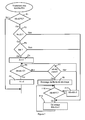
- FIG. 7 illustrates an exemplary embodiment of a flowchart which can be used by the microprocessor of the control circuit 11 to manage automatically overheating.
- step F8 If the difference ⁇ 8- ⁇ 6 is greater than a predetermined threshold (output Yes F7), it then proceeds to a step F8 of stirring the storage fluid. Through against, if the difference between the temperatures les8 and ⁇ 6 is small (output No of F7), it loops back to the input of step F5.
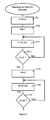
- FIG. 8 A particular embodiment of the brewing step, in which the stirring is carried out by periodically switching on the circulator S4, is illustrated in FIG. 8.
- t2 is equal to d2 (Yes output of F15)
- the microprocessor again checks, in a step F16 (FIG.
- step F8 the temperature ⁇ 8 has not dropped below 80 ° C (outlet Yes of F16)
- the discharge loop 12 is used during the day, as soon as the temperature ⁇ 8 exceeds 80 ° C.
- the operation of the auxiliary heating 5 and of the circulator S2 is, so conventional, controlled by the control circuit 11 as a function of the temperature storage fluid in the warmer top of the container storage 1, more particularly as a function of temperatures ⁇ 7 and ⁇ 8 measured respectively by the temperature sensors T7 and T8, so to keep the storage fluid at least at a set temperature predetermined in this part, of the order of 50 ° C for example for T8.
- the circulator S2 is stopped as soon as the temperature ⁇ 8 of the storage fluid reaches 50 ° C.
- variable speed circulator S3 is used to control the flow of the storage sent to the heated floor 6, in particular depending on the temperatures ⁇ 1, ⁇ 2, ⁇ 12 and ⁇ 13, measured respectively by the temperature T1, T2, T12 and T13, so as to regulate the temperature ⁇ 12 supplied by the T12 sensor, at the entrance to the heated floor.
- all energy from the solar collectors is, from preferably, transmitted by circulator S3 in the underfloor heating 6.
- the flow of the circulator S3 can then be controlled as a function of temperature ⁇ 13 measured by the temperature sensor T13, at the outlet of the heated floor 6.
- circulator S4 Apart from the brewing steps carried out during the night cooling, the operation of circulator S4 is, so conventional, controlled according to the flow rate signals D supplied by the detector proportional flow (not shown), placed in the cold water inlet (EF) upstream of the secondary circuit of the heat exchanger 10, and of the temperature ⁇ 9 measured by the temperature sensor T9.
- the speed of rotation of circulator S4 and, consequently, the flow rate of the storage fluid in the primary circuit of the heat exchanger 10, between the ends upper, hot, and lower, colder, of container 1 can be corrected according to the temperature ⁇ 11 of the domestic hot water (EC) measured by the temperature sensor T11.
- the management of overheating during a phase of night cooling can be used not only in an installation according to FIG. 5, in which the storage fluid circulates in the sensors solar 2, but also in any installation in which the collectors solar 2 are connected to a heat exchanger 3 located inside the storage container 1, as in the installations shown in the figures 1 to 4.
- the different thresholds used by the control circuit 11 can be programmed by any appropriate means, the time of verification of overheating can be changed and the duration of the summer period adapted to weather. Load shedding in the discharge loop can be carried out during a predetermined duration or be interrupted when the temperature ⁇ 8 is descended below a threshold different from the start-up threshold of the shedding.
Landscapes
- Engineering & Computer Science (AREA)
- Mechanical Engineering (AREA)
- Life Sciences & Earth Sciences (AREA)
- Sustainable Energy (AREA)
- Physics & Mathematics (AREA)
- Thermal Sciences (AREA)
- Chemical & Material Sciences (AREA)
- Sustainable Development (AREA)
- Combustion & Propulsion (AREA)
- General Engineering & Computer Science (AREA)
- Heat-Pump Type And Storage Water Heaters (AREA)
- Road Signs Or Road Markings (AREA)
- Cooling Or The Like Of Electrical Apparatus (AREA)
- Control Of Temperature (AREA)
- Steam Or Hot-Water Central Heating Systems (AREA)
- Central Heating Systems (AREA)
- Control Of High-Frequency Heating Circuits (AREA)
Applications Claiming Priority (2)
| Application Number | Priority Date | Filing Date | Title |
|---|---|---|---|
| FR0302226A FR2851644B1 (fr) | 2003-02-24 | 2003-02-24 | Installation solaire combinee comportant des moyens de gestion des surchauffes et procede de controle de l'installation |
| FR0302226 | 2003-02-24 |
Publications (2)
| Publication Number | Publication Date |
|---|---|
| EP1450109A1 true EP1450109A1 (de) | 2004-08-25 |
| EP1450109B1 EP1450109B1 (de) | 2006-05-17 |
Family
ID=32732059
Family Applications (1)
| Application Number | Title | Priority Date | Filing Date |
|---|---|---|---|
| EP04354006A Expired - Lifetime EP1450109B1 (de) | 2003-02-24 | 2004-02-24 | Kombinierte Solarheizungsanlage mit Überhitzungsverwaltung und Verfahren zur Regulierung der Anlage. |
Country Status (4)
| Country | Link |
|---|---|
| EP (1) | EP1450109B1 (de) |
| AT (1) | ATE326668T1 (de) |
| DE (1) | DE602004000871T2 (de) |
| FR (1) | FR2851644B1 (de) |
Cited By (6)
| Publication number | Priority date | Publication date | Assignee | Title |
|---|---|---|---|---|
| EP1788314A1 (de) * | 2005-11-17 | 2007-05-23 | Alois Schwarz | Heizungsanlage mit mindestens einer Wärmequelle |
| DE202009007493U1 (de) | 2009-05-26 | 2009-08-13 | F.W. Oventrop Gmbh & Co. Kg | Übergabestation für den gemeinsamen Anschluss von Solaranlagen und Brauchwasseranlagen an Speicher |
| WO2013092675A1 (fr) * | 2011-12-21 | 2013-06-27 | Feng Technologies (Fengtech) | Installation thermique |
| CN103528124A (zh) * | 2013-11-08 | 2014-01-22 | 西南科技大学 | 一种利用太阳能的蓄热采暖系统 |
| EP2902722A1 (de) * | 2014-01-31 | 2015-08-05 | Vaillant GmbH | Solarspeicher |
| EP2017550A3 (de) * | 2007-07-20 | 2016-05-25 | Cotherm | Steuervorrichtung zum Energiesparen eines Warmwasserboilers |
Families Citing this family (3)
| Publication number | Priority date | Publication date | Assignee | Title |
|---|---|---|---|---|
| FR3019881B1 (fr) | 2014-04-10 | 2019-03-22 | Centre National De La Recherche Scientifique | Dispositif et systeme de quantification d'energie thermique utile disponible dans un reservoir |
| DE102021113423A1 (de) | 2021-05-25 | 2022-12-01 | Greenage Ag | Energiewandlungsvorrichtung mit einer Brennstoffzelleneinheit |
| DE102023102658A1 (de) * | 2023-02-03 | 2024-08-08 | Citrinsolar Gmbh | Vorrichtung zur steuerung eines durchlauferhitzers für einen schichtladespeicher |
Citations (3)
| Publication number | Priority date | Publication date | Assignee | Title |
|---|---|---|---|---|
| US4399807A (en) * | 1981-06-09 | 1983-08-23 | Chevron Research Company | Method and apparatus for overtemperature control of solar water heating system |
| US6357512B1 (en) * | 2000-07-26 | 2002-03-19 | Zomeworks | Passive heating and cooling system |
| US20020112435A1 (en) * | 2000-07-03 | 2002-08-22 | Hartman Paul H. | Demand side management structures |
-
2003
- 2003-02-24 FR FR0302226A patent/FR2851644B1/fr not_active Expired - Fee Related
-
2004
- 2004-02-24 DE DE602004000871T patent/DE602004000871T2/de not_active Expired - Lifetime
- 2004-02-24 AT AT04354006T patent/ATE326668T1/de not_active IP Right Cessation
- 2004-02-24 EP EP04354006A patent/EP1450109B1/de not_active Expired - Lifetime
Patent Citations (3)
| Publication number | Priority date | Publication date | Assignee | Title |
|---|---|---|---|---|
| US4399807A (en) * | 1981-06-09 | 1983-08-23 | Chevron Research Company | Method and apparatus for overtemperature control of solar water heating system |
| US20020112435A1 (en) * | 2000-07-03 | 2002-08-22 | Hartman Paul H. | Demand side management structures |
| US6357512B1 (en) * | 2000-07-26 | 2002-03-19 | Zomeworks | Passive heating and cooling system |
Cited By (7)
| Publication number | Priority date | Publication date | Assignee | Title |
|---|---|---|---|---|
| EP1788314A1 (de) * | 2005-11-17 | 2007-05-23 | Alois Schwarz | Heizungsanlage mit mindestens einer Wärmequelle |
| EP2017550A3 (de) * | 2007-07-20 | 2016-05-25 | Cotherm | Steuervorrichtung zum Energiesparen eines Warmwasserboilers |
| DE202009007493U1 (de) | 2009-05-26 | 2009-08-13 | F.W. Oventrop Gmbh & Co. Kg | Übergabestation für den gemeinsamen Anschluss von Solaranlagen und Brauchwasseranlagen an Speicher |
| WO2013092675A1 (fr) * | 2011-12-21 | 2013-06-27 | Feng Technologies (Fengtech) | Installation thermique |
| FR2985000A1 (fr) * | 2011-12-21 | 2013-06-28 | Feng Technologies Fengtech | Installation thermique |
| CN103528124A (zh) * | 2013-11-08 | 2014-01-22 | 西南科技大学 | 一种利用太阳能的蓄热采暖系统 |
| EP2902722A1 (de) * | 2014-01-31 | 2015-08-05 | Vaillant GmbH | Solarspeicher |
Also Published As
| Publication number | Publication date |
|---|---|
| ATE326668T1 (de) | 2006-06-15 |
| EP1450109B1 (de) | 2006-05-17 |
| DE602004000871T2 (de) | 2006-11-30 |
| DE602004000871D1 (de) | 2006-06-22 |
| FR2851644B1 (fr) | 2005-09-02 |
| FR2851644A1 (fr) | 2004-08-27 |
Similar Documents
| Publication | Publication Date | Title |
|---|---|---|
| EP1450109B1 (de) | Kombinierte Solarheizungsanlage mit Überhitzungsverwaltung und Verfahren zur Regulierung der Anlage. | |
| WO2014044864A1 (fr) | Installation de chauffe-eau sanitaire à fonction de chauffage | |
| EP3225922B1 (de) | Kühl-, klimatisierungs- oder heizsystem | |
| FR2935781A1 (fr) | Procede de regulation d'une installation de chauffage comportant au moins une pompe a chaleur et un moyen de chauffage complementaire | |
| FR3031575A1 (fr) | Module de transfert thermique avec regulation associee pour systeme thermodynamique de production d'eau chaude sanitaire | |
| FR2976347A1 (fr) | Procede de regulation d'un systeme de production d'eau chaude, unite de regulation et systeme de production d'eau chaude | |
| CA3132008A1 (fr) | Systeme pour reduire un risque de contamination bacterienne d'un chauffe-eau | |
| EP4124803B1 (de) | Steuerverfahren eines thermodynamischen speicher- und heizsystems | |
| FR3018902A1 (fr) | Installation de production d'eau chaude sanitaire et procede de pilotage de cette installation | |
| FR2805031A1 (fr) | Systeme de chauffage et de climatisation | |
| FR2870928A1 (fr) | Procede de production solaire instantane prioritaire dans les installations utilisant des capteurs solaires thermiques basse temperature | |
| WO2013093246A1 (fr) | Procédé de gestion d'un système de pompe à chaleur, système de pompe à chaleur, et installation de chauffage comprenant un tel système | |
| WO2021110791A1 (fr) | Systeme de distribution d'eau | |
| EP3480526B1 (de) | Heiz- und/oder warmwassererzeugungsanlage für den sanitärbereich in einem gebäude | |
| EP3581853B1 (de) | Wärmeübertragungsmodul für die erzeugung von warmwasser | |
| EP1450108A1 (de) | Kombinierte Anlage für Solarheizung und Brauchwassererwärmung | |
| FR3052793A1 (fr) | Dispositif pour transferer rapidement de l'eau chaude d'une source vers un utilisateur ou bien une machine. | |
| FR2912809A1 (fr) | Systeme de chauffage solaire independant, avec stockage intersaison, gestion centralisee, vidange et remplissage automatique des capteurs solaires et utililsant un fluide caloporteur a haute temperature. | |
| EP0942238A1 (de) | Zentralheizung benutzende Heiz- und Klimaanlage | |
| EP2947393B1 (de) | Schutzumlauf gegen überhitzungseffekte in einem heisswasserbereitungssystem, und entsprechendes heisswasserbereitungssystem | |
| WO2013038114A1 (fr) | Dispositif et procédé de chauffage d'une eau de bassin | |
| FR3054875B1 (fr) | Installation de production d'eau chaude sanitaire et procede de pilotage de cette installation | |
| EP3824227A1 (de) | Wasserheizsystem mit vorwärmung durch erneuerbare energie ergänzt durch sofortiges erhitzen | |
| FR2999687A1 (fr) | Dispositif accumulateur d'eau chaude | |
| WO2014095415A1 (fr) | Installation de fourniture d'eau chaude sanitaire dans un bâtiment |
Legal Events
| Date | Code | Title | Description |
|---|---|---|---|
| PUAI | Public reference made under article 153(3) epc to a published international application that has entered the european phase |
Free format text: ORIGINAL CODE: 0009012 |
|
| AK | Designated contracting states |
Kind code of ref document: A1 Designated state(s): AT BE BG CH CY CZ DE DK EE ES FI FR GB GR HU IE IT LI LU MC NL PT RO SE SI SK TR |
|
| AX | Request for extension of the european patent |
Extension state: AL HR LT LV MK |
|
| 17P | Request for examination filed |
Effective date: 20050217 |
|
| AKX | Designation fees paid |
Designated state(s): AT BE BG CH CY CZ DE DK EE ES FI FR GB GR HU IE IT LI LU MC NL PT RO SE SI SK TR |
|
| GRAP | Despatch of communication of intention to grant a patent |
Free format text: ORIGINAL CODE: EPIDOSNIGR1 |
|
| GRAS | Grant fee paid |
Free format text: ORIGINAL CODE: EPIDOSNIGR3 |
|
| GRAA | (expected) grant |
Free format text: ORIGINAL CODE: 0009210 |
|
| AK | Designated contracting states |
Kind code of ref document: B1 Designated state(s): AT BE BG CH CY CZ DE DK EE ES FI GB GR HU IE IT LI LU MC NL PT RO SE SI SK TR |
|
| PG25 | Lapsed in a contracting state [announced via postgrant information from national office to epo] |
Ref country code: IT Free format text: LAPSE BECAUSE OF FAILURE TO SUBMIT A TRANSLATION OF THE DESCRIPTION OR TO PAY THE FEE WITHIN THE PRESCRIBED TIME-LIMIT;WARNING: LAPSES OF ITALIAN PATENTS WITH EFFECTIVE DATE BEFORE 2007 MAY HAVE OCCURRED AT ANY TIME BEFORE 2007. THE CORRECT EFFECTIVE DATE MAY BE DIFFERENT FROM THE ONE RECORDED. Effective date: 20060517 Ref country code: GB Free format text: LAPSE BECAUSE OF FAILURE TO SUBMIT A TRANSLATION OF THE DESCRIPTION OR TO PAY THE FEE WITHIN THE PRESCRIBED TIME-LIMIT Effective date: 20060517 Ref country code: SI Free format text: LAPSE BECAUSE OF FAILURE TO SUBMIT A TRANSLATION OF THE DESCRIPTION OR TO PAY THE FEE WITHIN THE PRESCRIBED TIME-LIMIT Effective date: 20060517 Ref country code: CZ Free format text: LAPSE BECAUSE OF FAILURE TO SUBMIT A TRANSLATION OF THE DESCRIPTION OR TO PAY THE FEE WITHIN THE PRESCRIBED TIME-LIMIT Effective date: 20060517 Ref country code: SK Free format text: LAPSE BECAUSE OF FAILURE TO SUBMIT A TRANSLATION OF THE DESCRIPTION OR TO PAY THE FEE WITHIN THE PRESCRIBED TIME-LIMIT Effective date: 20060517 Ref country code: NL Free format text: LAPSE BECAUSE OF FAILURE TO SUBMIT A TRANSLATION OF THE DESCRIPTION OR TO PAY THE FEE WITHIN THE PRESCRIBED TIME-LIMIT Effective date: 20060517 Ref country code: FI Free format text: LAPSE BECAUSE OF FAILURE TO SUBMIT A TRANSLATION OF THE DESCRIPTION OR TO PAY THE FEE WITHIN THE PRESCRIBED TIME-LIMIT Effective date: 20060517 Ref country code: RO Free format text: LAPSE BECAUSE OF FAILURE TO SUBMIT A TRANSLATION OF THE DESCRIPTION OR TO PAY THE FEE WITHIN THE PRESCRIBED TIME-LIMIT Effective date: 20060517 Ref country code: IE Free format text: LAPSE BECAUSE OF FAILURE TO SUBMIT A TRANSLATION OF THE DESCRIPTION OR TO PAY THE FEE WITHIN THE PRESCRIBED TIME-LIMIT Effective date: 20060517 |
|
| REG | Reference to a national code |
Ref country code: GB Ref legal event code: FG4D Free format text: NOT ENGLISH |
|
| REG | Reference to a national code |
Ref country code: CH Ref legal event code: EP |
|
| REG | Reference to a national code |
Ref country code: IE Ref legal event code: FG4D Free format text: LANGUAGE OF EP DOCUMENT: FRENCH |
|
| REF | Corresponds to: |
Ref document number: 602004000871 Country of ref document: DE Date of ref document: 20060622 Kind code of ref document: P |
|
| PG25 | Lapsed in a contracting state [announced via postgrant information from national office to epo] |
Ref country code: SE Free format text: LAPSE BECAUSE OF FAILURE TO SUBMIT A TRANSLATION OF THE DESCRIPTION OR TO PAY THE FEE WITHIN THE PRESCRIBED TIME-LIMIT Effective date: 20060817 Ref country code: DK Free format text: LAPSE BECAUSE OF FAILURE TO SUBMIT A TRANSLATION OF THE DESCRIPTION OR TO PAY THE FEE WITHIN THE PRESCRIBED TIME-LIMIT Effective date: 20060817 |
|
| PG25 | Lapsed in a contracting state [announced via postgrant information from national office to epo] |
Ref country code: ES Free format text: LAPSE BECAUSE OF FAILURE TO SUBMIT A TRANSLATION OF THE DESCRIPTION OR TO PAY THE FEE WITHIN THE PRESCRIBED TIME-LIMIT Effective date: 20060828 |
|
| PG25 | Lapsed in a contracting state [announced via postgrant information from national office to epo] |
Ref country code: PT Free format text: LAPSE BECAUSE OF FAILURE TO SUBMIT A TRANSLATION OF THE DESCRIPTION OR TO PAY THE FEE WITHIN THE PRESCRIBED TIME-LIMIT Effective date: 20061017 |
|
| NLV1 | Nl: lapsed or annulled due to failure to fulfill the requirements of art. 29p and 29m of the patents act | ||
| GBV | Gb: ep patent (uk) treated as always having been void in accordance with gb section 77(7)/1977 [no translation filed] |
Effective date: 20060517 |
|
| REG | Reference to a national code |
Ref country code: IE Ref legal event code: FD4D |
|
| PG25 | Lapsed in a contracting state [announced via postgrant information from national office to epo] |
Ref country code: MC Free format text: LAPSE BECAUSE OF NON-PAYMENT OF DUE FEES Effective date: 20070228 |
|
| PLBE | No opposition filed within time limit |
Free format text: ORIGINAL CODE: 0009261 |
|
| STAA | Information on the status of an ep patent application or granted ep patent |
Free format text: STATUS: NO OPPOSITION FILED WITHIN TIME LIMIT |
|
| 26N | No opposition filed |
Effective date: 20070220 |
|
| BERE | Be: lapsed |
Owner name: CLIPSOL Effective date: 20070228 |
|
| PG25 | Lapsed in a contracting state [announced via postgrant information from national office to epo] |
Ref country code: BE Free format text: LAPSE BECAUSE OF NON-PAYMENT OF DUE FEES Effective date: 20070228 |
|
| PG25 | Lapsed in a contracting state [announced via postgrant information from national office to epo] |
Ref country code: GR Free format text: LAPSE BECAUSE OF FAILURE TO SUBMIT A TRANSLATION OF THE DESCRIPTION OR TO PAY THE FEE WITHIN THE PRESCRIBED TIME-LIMIT Effective date: 20060818 |
|
| PG25 | Lapsed in a contracting state [announced via postgrant information from national office to epo] |
Ref country code: BG Free format text: LAPSE BECAUSE OF FAILURE TO SUBMIT A TRANSLATION OF THE DESCRIPTION OR TO PAY THE FEE WITHIN THE PRESCRIBED TIME-LIMIT Effective date: 20060817 |
|
| PG25 | Lapsed in a contracting state [announced via postgrant information from national office to epo] |
Ref country code: EE Free format text: LAPSE BECAUSE OF FAILURE TO SUBMIT A TRANSLATION OF THE DESCRIPTION OR TO PAY THE FEE WITHIN THE PRESCRIBED TIME-LIMIT Effective date: 20060517 |
|
| PG25 | Lapsed in a contracting state [announced via postgrant information from national office to epo] |
Ref country code: CY Free format text: LAPSE BECAUSE OF FAILURE TO SUBMIT A TRANSLATION OF THE DESCRIPTION OR TO PAY THE FEE WITHIN THE PRESCRIBED TIME-LIMIT Effective date: 20060517 Ref country code: LU Free format text: LAPSE BECAUSE OF NON-PAYMENT OF DUE FEES Effective date: 20070224 |
|
| PG25 | Lapsed in a contracting state [announced via postgrant information from national office to epo] |
Ref country code: HU Free format text: LAPSE BECAUSE OF FAILURE TO SUBMIT A TRANSLATION OF THE DESCRIPTION OR TO PAY THE FEE WITHIN THE PRESCRIBED TIME-LIMIT Effective date: 20061118 Ref country code: TR Free format text: LAPSE BECAUSE OF FAILURE TO SUBMIT A TRANSLATION OF THE DESCRIPTION OR TO PAY THE FEE WITHIN THE PRESCRIBED TIME-LIMIT Effective date: 20060517 |
|
| PGFP | Annual fee paid to national office [announced via postgrant information from national office to epo] |
Ref country code: CH Payment date: 20100215 Year of fee payment: 7 |
|
| PGFP | Annual fee paid to national office [announced via postgrant information from national office to epo] |
Ref country code: AT Payment date: 20100212 Year of fee payment: 7 Ref country code: DE Payment date: 20100303 Year of fee payment: 7 |
|
| REG | Reference to a national code |
Ref country code: CH Ref legal event code: PL |
|
| PG25 | Lapsed in a contracting state [announced via postgrant information from national office to epo] |
Ref country code: CH Free format text: LAPSE BECAUSE OF NON-PAYMENT OF DUE FEES Effective date: 20110228 Ref country code: LI Free format text: LAPSE BECAUSE OF NON-PAYMENT OF DUE FEES Effective date: 20110228 |
|
| PG25 | Lapsed in a contracting state [announced via postgrant information from national office to epo] |
Ref country code: AT Free format text: LAPSE BECAUSE OF NON-PAYMENT OF DUE FEES Effective date: 20110224 |
|
| REG | Reference to a national code |
Ref country code: DE Ref legal event code: R119 Ref document number: 602004000871 Country of ref document: DE Effective date: 20110901 |
|
| PG25 | Lapsed in a contracting state [announced via postgrant information from national office to epo] |
Ref country code: DE Free format text: LAPSE BECAUSE OF NON-PAYMENT OF DUE FEES Effective date: 20110901 |