EP1450139A2 - Verfahren und Gerät zur Bestimmung des Massendurchsatzes durch einen Motor - Google Patents
Verfahren und Gerät zur Bestimmung des Massendurchsatzes durch einen Motor Download PDFInfo
- Publication number
- EP1450139A2 EP1450139A2 EP04250433A EP04250433A EP1450139A2 EP 1450139 A2 EP1450139 A2 EP 1450139A2 EP 04250433 A EP04250433 A EP 04250433A EP 04250433 A EP04250433 A EP 04250433A EP 1450139 A2 EP1450139 A2 EP 1450139A2
- Authority
- EP
- European Patent Office
- Prior art keywords
- engine
- carbon dioxide
- concentration
- ratio
- mass flow
- Prior art date
- Legal status (The legal status is an assumption and is not a legal conclusion. Google has not performed a legal analysis and makes no representation as to the accuracy of the status listed.)
- Granted
Links
- 238000000034 method Methods 0.000 title claims abstract description 33
- CURLTUGMZLYLDI-UHFFFAOYSA-N Carbon dioxide Chemical compound O=C=O CURLTUGMZLYLDI-UHFFFAOYSA-N 0.000 claims abstract description 288
- 229910002092 carbon dioxide Inorganic materials 0.000 claims abstract description 152
- 239000001569 carbon dioxide Substances 0.000 claims abstract description 144
- 239000007789 gas Substances 0.000 claims abstract description 127
- 239000000446 fuel Substances 0.000 claims abstract description 66
- 230000005855 radiation Effects 0.000 claims abstract description 24
- 229910001868 water Inorganic materials 0.000 claims description 74
- XLYOFNOQVPJJNP-UHFFFAOYSA-N water Substances O XLYOFNOQVPJJNP-UHFFFAOYSA-N 0.000 claims description 69
- QVGXLLKOCUKJST-UHFFFAOYSA-N atomic oxygen Chemical compound [O] QVGXLLKOCUKJST-UHFFFAOYSA-N 0.000 claims description 62
- 239000001301 oxygen Substances 0.000 claims description 62
- 229910052760 oxygen Inorganic materials 0.000 claims description 62
- 230000001678 irradiating effect Effects 0.000 claims description 4
- 238000000862 absorption spectrum Methods 0.000 abstract description 25
- 238000002485 combustion reaction Methods 0.000 description 23
- 238000001228 spectrum Methods 0.000 description 16
- 239000004215 Carbon black (E152) Substances 0.000 description 9
- 229930195733 hydrocarbon Natural products 0.000 description 9
- 150000002430 hydrocarbons Chemical class 0.000 description 9
- 238000000295 emission spectrum Methods 0.000 description 6
- 238000005259 measurement Methods 0.000 description 6
- 238000010521 absorption reaction Methods 0.000 description 5
- OKTJSMMVPCPJKN-UHFFFAOYSA-N Carbon Chemical compound [C] OKTJSMMVPCPJKN-UHFFFAOYSA-N 0.000 description 4
- 229910052799 carbon Inorganic materials 0.000 description 4
- VUZPPFZMUPKLLV-UHFFFAOYSA-N methane;hydrate Chemical compound C.O VUZPPFZMUPKLLV-UHFFFAOYSA-N 0.000 description 4
- 238000012544 monitoring process Methods 0.000 description 4
- 239000000203 mixture Substances 0.000 description 3
- 238000004847 absorption spectroscopy Methods 0.000 description 2
- UGFAIRIUMAVXCW-UHFFFAOYSA-N Carbon monoxide Chemical compound [O+]#[C-] UGFAIRIUMAVXCW-UHFFFAOYSA-N 0.000 description 1
- UFHFLCQGNIYNRP-UHFFFAOYSA-N Hydrogen Chemical compound [H][H] UFHFLCQGNIYNRP-UHFFFAOYSA-N 0.000 description 1
- UBAZGMLMVVQSCD-UHFFFAOYSA-N carbon dioxide;molecular oxygen Chemical compound O=O.O=C=O UBAZGMLMVVQSCD-UHFFFAOYSA-N 0.000 description 1
- 229910002091 carbon monoxide Inorganic materials 0.000 description 1
- 238000009833 condensation Methods 0.000 description 1
- 230000005494 condensation Effects 0.000 description 1
- 238000001816 cooling Methods 0.000 description 1
- 238000012937 correction Methods 0.000 description 1
- 230000000694 effects Effects 0.000 description 1
- 239000001257 hydrogen Substances 0.000 description 1
- 229910052739 hydrogen Inorganic materials 0.000 description 1
- 230000003287 optical effect Effects 0.000 description 1
- 239000000126 substance Substances 0.000 description 1
- 238000006467 substitution reaction Methods 0.000 description 1
- 238000012360 testing method Methods 0.000 description 1
- 230000001052 transient effect Effects 0.000 description 1
Images


Classifications
-
- F—MECHANICAL ENGINEERING; LIGHTING; HEATING; WEAPONS; BLASTING
- F01—MACHINES OR ENGINES IN GENERAL; ENGINE PLANTS IN GENERAL; STEAM ENGINES
- F01D—NON-POSITIVE DISPLACEMENT MACHINES OR ENGINES, e.g. STEAM TURBINES
- F01D17/00—Regulating or controlling by varying flow
- F01D17/02—Arrangement of sensing elements
- F01D17/08—Arrangement of sensing elements responsive to condition of working-fluid, e.g. pressure
-
- G—PHYSICS
- G01—MEASURING; TESTING
- G01F—MEASURING VOLUME, VOLUME FLOW, MASS FLOW OR LIQUID LEVEL; METERING BY VOLUME
- G01F9/00—Measuring volume flow relative to another variable, e.g. of liquid fuel for an engine
- G01F9/001—Measuring volume flow relative to another variable, e.g. of liquid fuel for an engine with electric, electro-mechanic or electronic means
-
- G—PHYSICS
- G01—MEASURING; TESTING
- G01N—INVESTIGATING OR ANALYSING MATERIALS BY DETERMINING THEIR CHEMICAL OR PHYSICAL PROPERTIES
- G01N21/00—Investigating or analysing materials by the use of optical means, i.e. using sub-millimetre waves, infrared, visible or ultraviolet light
- G01N21/17—Systems in which incident light is modified in accordance with the properties of the material investigated
- G01N21/25—Colour; Spectral properties, i.e. comparison of effect of material on the light at two or more different wavelengths or wavelength bands
- G01N21/31—Investigating relative effect of material at wavelengths characteristic of specific elements or molecules, e.g. atomic absorption spectrometry
- G01N21/35—Investigating relative effect of material at wavelengths characteristic of specific elements or molecules, e.g. atomic absorption spectrometry using infrared light
- G01N21/3504—Investigating relative effect of material at wavelengths characteristic of specific elements or molecules, e.g. atomic absorption spectrometry using infrared light for analysing gases, e.g. multi-gas analysis
-
- G—PHYSICS
- G01—MEASURING; TESTING
- G01N—INVESTIGATING OR ANALYSING MATERIALS BY DETERMINING THEIR CHEMICAL OR PHYSICAL PROPERTIES
- G01N21/00—Investigating or analysing materials by the use of optical means, i.e. using sub-millimetre waves, infrared, visible or ultraviolet light
- G01N21/17—Systems in which incident light is modified in accordance with the properties of the material investigated
- G01N21/25—Colour; Spectral properties, i.e. comparison of effect of material on the light at two or more different wavelengths or wavelength bands
- G01N21/31—Investigating relative effect of material at wavelengths characteristic of specific elements or molecules, e.g. atomic absorption spectrometry
- G01N21/39—Investigating relative effect of material at wavelengths characteristic of specific elements or molecules, e.g. atomic absorption spectrometry using tunable lasers
-
- G—PHYSICS
- G01—MEASURING; TESTING
- G01N—INVESTIGATING OR ANALYSING MATERIALS BY DETERMINING THEIR CHEMICAL OR PHYSICAL PROPERTIES
- G01N21/00—Investigating or analysing materials by the use of optical means, i.e. using sub-millimetre waves, infrared, visible or ultraviolet light
- G01N21/17—Systems in which incident light is modified in accordance with the properties of the material investigated
- G01N21/25—Colour; Spectral properties, i.e. comparison of effect of material on the light at two or more different wavelengths or wavelength bands
- G01N21/31—Investigating relative effect of material at wavelengths characteristic of specific elements or molecules, e.g. atomic absorption spectrometry
- G01N21/35—Investigating relative effect of material at wavelengths characteristic of specific elements or molecules, e.g. atomic absorption spectrometry using infrared light
- G01N2021/3595—Investigating relative effect of material at wavelengths characteristic of specific elements or molecules, e.g. atomic absorption spectrometry using infrared light using FTIR
Definitions
- the present invention relates to a method and apparatus for determining the mass flow through an engine, the present invention relates in particular to a method and apparatus for determining the mass flow through a gas turbine engine.
- the present invention seeks to provide a novel method and apparatus, which reduces, preferably overcomes, the above-mentioned problems.
- the present invention provides a method for determining the total mass flow through an engine comprising measuring the fuel flow to the engine, measuring the concentration of carbon dioxide, measuring the ratio of water to oxygen, measuring the ratio of carbon dioxide to oxygen or measuring the ratio of water to carbon dioxide in the gases exhausted from the engine, determining the air to fuel ratio in the engine from the fuel flow and the concentration of carbon dioxide, the ratio of water to oxygen, the ratio of carbon dioxide to oxygen or the ratio of water to carbon dioxide, determining the air mass flow through the engine from the air to fuel ratio and calculating the total air and fuel mass flow through the engine by adding the air mass flow through the engine to the fuel mass flow to the engine.
- Measuring the concentration of carbon dioxide may comprise detecting infrared radiation emitted by carbon dioxide in the gases exhausted from the engine and determining the concentration of carbon dioxide.
- Preferably measuring the concentration of carbon dioxide comprises detecting infrared radiation absorbed by carbon dioxide in the gases exhausted from the engine and determining the concentration of carbon dioxide.
- Preferably measuring the ratio of water to oxygen comprises detecting infra-red radiation absorbed by water in the gases exhausted from the engine, detecting near infra-red radiation absorbed by oxygen in the gases exhausted from the engine, determining the concentration of water, determining the concentration of oxygen and calculating the ratio of water to oxygen.
- Preferably measuring the ratio of carbon dioxide to oxygen comprises detecting infra-red radiation absorbed by carbon dioxide in the gases exhausted from the engine, detecting near infra-red radiation absorbed by oxygen in the gases exhausted from the engine, determining the concentration of carbon dioxide, determining the concentration of oxygen and calculating the ratio of carbon dioxide to oxygen.
- Preferably measuring the ratio of water to carbon dioxide comprises detecting infrared radiation absorbed by water in the gases exhausted from the engine, detecting infrared radiation absorbed by carbon dioxide in the gases exhausted from the engine, determining the concentration of water, determining the concentration of carbon dioxide and calculating the ratio of water to carbon dioxide.
- the method comprises irradiating the gases exhausted from the engine with a light.
- the method comprises irradiating the gases exhausted from the engine with a laser light.
- the method comprises detecting infrared radiation absorbed or emitted by the gases exhausted from the engine at a plurality of lines across the exhaust of the engine.
- the method may comprise moving a detector.
- the method may comprise moving a light source.
- the method comprises moving at least one mirror.
- the engine is a gas turbine engine. More preferably the engine is a turbofan gas turbine engine.
- the present invention also provides an apparatus for determining the total mass flow through an engine comprising means for measuring the fuel flow to the engine, means for measuring the concentration of carbon dioxide, means for measuring the ratio of water to oxygen, means for measuring the ratio of carbon dioxide to oxygen or means for measuring the ratio of water to carbon dioxide in the gases exhausted from the engine, means for determining the air to fuel ratio in the engine from the fuel flow and the concentration of carbon dioxide, the ratio of water to oxygen, the ratio of carbon dioxide to oxygen or the ratio of water to carbon dioxide, means for determining the air mass flow through the engine from the air to fuel ratio and means for calculating the total air and fuel mass flow through the engine by adding the air mass flow through the engine to the fuel mass flow to the engine.
- the engine is a gas turbine engine. More preferably the gas turbine engine is a turbofan gas turbine engine.
- the means for measuring the concentration of carbon dioxide comprises at least one detector.
- the detector comprises a spectrometer and a photo-detector, the spectrometer is optically coupled to the photo-detector.
- the spectrometer is a Fourier transform spectrometer.
- the means for measuring the concentration of carbon dioxide comprises a light source.
- the light source is a laser.
- the laser may be a tunable laser.
- the laser is a diode laser.
- There may be a plurality of lasers. The lasers may be tuned to different wavelengths, there are means to switch the lasers on sequentially.
- the means to scan may comprise one or more mirrors.
- the total concentration of carbon containing species, carbon dioxide, carbon monoxide, carbon and unburned hydrocarbon, or water in a core exhaust of a gas turbine engine is measured, then the total mass flow can be calculated provided the empirical formula of the hydrocarbon fuel is known.
- Water is the only hydrogen containing combustion product, although when combustion is inefficient, the presence of unburned hydrocarbon may introduce small errors in mass flow based on water concentration measurement. There is an appreciable concentration of water vapour in the atmosphere and allowance is made for this, based on its measurement at the time of test. Water may condense in the engine intake under some atmospheric conditions causing the air entering the core engine to be drier than atmospheric air and allowance is made for this.
- the X H2O /X CO2 ratio after correction for ambient humidity may be smaller than n/2m due to intake water condensation, or it may be larger than n/2m due to combustion inefficiency. Both these effects may compete. If the composition of the hydrocarbon fuel, and hence the values of m and n are accurately determined, then the core mass flow can be found from X CO2 /X O2 , X H2O /X O2 and X H2O /X CO2 ratios.
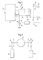
- a turbofan gas turbine engine 10 as shown in figure 1, comprises in axial flow series an inlet 12, a fan section 14, a compressor section 16, a combustion section 18, a turbine section 20 and a core exhaust 22.
- the fan section 14 has a fan exhaust 24.
- the compressor section 16, the combustion section 18, the turbine section 20 and the exhaust 22 form the core engine 26 of the turbofan gas turbine engine 10.
- the means 28 for determining the total mass flow through the core engine 26 of the turbofan gas turbine engine 10 comprises means 30 to measure the fuel flow to the combustion section 18 of the turbofan gas turbine engine 10.
- the means 30 for measuring the fuel flow to the combustion section 18 comprises a fuel meter 32 arranged in a pipe 34 supplying fuel to the combustion section 18.
- the means 28 for determining the total mass flow through the core engine 26 of the turbofan gas turbine engine 10 comprises means 36 for measuring the concentration of carbon dioxide in the exhaust gases leaving the exhaust 22 of the core engine 26 of the turbofan gas turbine engine 10.
- the means 36 for determining the concentration of carbon dioxide in the exhaust gases leaving the exhaust 22 of the core engine 26 of the turbofan gas turbine engine 10 comprises a tunable laser 38 and a first mirror 40 to direct a laser beam 42 through the exhaust gases leaving the exhaust 22 and a second mirror 44 to direct the laser beam 42, after passing through the exhaust gases leaving the exhaust 22, to a detector 46.
- the mirrors 40 and 44 are movable to allow the laser beam 42 to be scanned across at least a sufficient number of lines of sight such that substantially the whole of the cross-sectional area of the exhaust 22 is scanned so that an average measurement of the concentration is produced.
- the means 28 for determining the total mass flow through the core engine 26 of the turbofan gas turbine engine 10 comprises means 48 for determining the air to fuel ratio in the engine from the fuel flow and the concentration of carbon dioxide.
- the means 28 for determining the total mass flow through the core engine 26 of the turbofan gas turbine engine 10 comprises means 48 for determining the air mass flow through the core engine 26 of the turbofan gas turbine engine 10 from the air to fuel ratio and there are means 48 for calculating the total air and fuel mass flow through the core engine 26 of the turbofan gas turbine engine 10 by adding the air mass flow through the core engine 26 of the turbofan gas turbine engine 10 to the fuel mass flow to the combustion section 18 of the turbofan gas turbine engine 10.
- the means 48 may be a computer or personal computer etc.
- a method for determining the total mass flow through the core engine 26 of the turbofan gas turbine engine 10 is to measure the absolute carbon dioxide concentration in the exhaust gases leaving the exhaust 22 of the core engine 26 of the turbofan gas turbine engine 10.
- the absolute carbon dioxide concentration is measured using absorption spectroscopy, in which radiation absorbed by the carbon dioxide in the field of view of a detector 46 is measured.
- the detector 46 is a spectrometer, which is optically coupled to a photo-detector, preferably the spectrometer is a Fourier transform spectrometer. Alternatively the detector 46 may be a wavelength selecting filter optically coupled to a photo-detector. Carbon dioxide has many absorption lines in the infrared region.
- the field of view of the detector 46 is scanned across the whole of the exhaust 22 of the core engine 26 of the turbofan gas turbine engine 10 so that the average carbon dioxide concentration is determined, as shown in figures 1 and 2.
- the tunable laser 38 limits the field of view of the detector 46 and provides good accuracy.
- Other light sources besides a laser may be used to produce the absorption spectrum.
- Each line of sight of the detector 46 comprises a plurality of points through the exhaust gases and each point is at a different temperature and therefore the measured carbon dioxide absorption spectrum at each position is different.
- the measured carbon dioxide absorption spectrum for each point is compared to a plurality of calculated simulated carbon dioxide absorption spectra to find a match.
- the calculated simulated carbon dioxide absorption spectra correspond to different temperatures and the amplitude of the peaks in the calculated simulated carbon dioxide absorption spectra indicate the concentration of the carbon dioxide.
- the concentration of carbon dioxide at each point is determined by comparing the amplitude of the peaks in the measured carbon dioxide spectrum and the matched calculated simulated carbon dioxide spectrum and scaled accordingly.
- the carbon dioxide concentrations at all the points in a line of sight and for all the lines of sight are added together to produce an average carbon dioxide concentration.
- the carbon dioxide spectrum depends upon the temperature profile of the exhaust gases leaving the exhaust 22 of the core engine 26 of the turbofan gas turbine engine 10.
- the temperature of the exhaust gases leaving the exhaust 22 of the core engine 26 of the turbofan gas turbine engine 10 is determined by monitoring the carbon dioxide absorption spectrum at different wavelengths of the carbon dioxide spectrum, in the laser case, by switching the laser wavelength between different regions of the absorption spectrum and keeping a single detector 46, thus by looking for absorption peaks at different wavelengths.
- the means 28B for determining the total mass flow through the core engine 26 of the turbofan gas turbine engine 10 comprises means 30 to measure the fuel flow to the combustion section 18 of the turbofan gas turbine engine 10.
- the means 30 for measuring the fuel flow to the combustion section 18 comprises a fuel meter 32 arranged in a pipe 34 supplying fuel to the combustion section 18.
- the means 28B for determining the total mass flow through the core engine 26 of the turbofan gas turbine engine 10 comprises means 36B for determining the ratio of water to oxygen, the ratio of carbon dioxide to oxygen or the ratio of water to carbon dioxide in the exhaust gases leaving the exhaust 22 of the core engine 26 of the turbofan gas turbine engine 10.
- the means 36 for determining the ratio of water to oxygen, the ratio of carbon dioxide to oxygen or the ratio of water to carbon dioxide in the exhaust gases leaving the exhaust 22 of the core engine 26 of the turbofan gas turbine engine 10 comprises three lasers 38A, 38B and 38C and a first mirror 40 to direct a laser beam 42 through the exhaust gases leaving the exhaust 22 and a second mirror 44 to direct the laser beam 42, after passing through the exhaust gases leaving the exhaust 22, to a detector 46.
- the mirrors 40 and 44 are movable to allow the laser beam 42 to be scanned across at least a sufficient number of lines of sight such that substantially the whole of the cross-sectional area of the exhaust 22 is scanned so that an average measurement of the concentration is produced.
- the laser 38A is used to measure the concentration of carbon dioxide
- the laser 38B is used to measure the concentration of oxygen
- the laser 38C is used to measure the concentration of water.
- the means 28 for determining the total mass flow through the core engine 26 of the turbofan gas turbine engine 10 comprises means 48 for determining the air to fuel ratio in the engine from the fuel flow and the ratio of water to oxygen, the ratio of carbon dioxide to oxygen or the ratio of water to carbon dioxide.
- the means 28 for determining the total mass flow through the core engine 26 of the turbofan gas turbine engine 10 comprises means 48 for determining the air mass flow through the core engine 26 of the turbofan gas turbine engine 10 from the air to fuel ratio and there are means 48 for calculating the total air and fuel mass flow through the core engine 26 of the turbofan gas turbine engine 10 by adding the air mass flow through the core engine 26 of the turbofan gas turbine engine 10 to the fuel mass flow to the combustion section 18 of the turbofan gas turbine engine 10.
- the means 48 may be a computer or personal computer etc.
- a method for determining the total mass flow through the core engine 26 of the turbofan gas turbine engine 10 is to measure the absolute carbon dioxide concentration, the absolute oxygen concentration and the absolute water concentration in the exhaust gases leaving the exhaust 22 of the core engine 26 of the turbofan gas turbine engine 10.
- the absolute carbon dioxide concentration, the absolute oxygen concentration and the absolute water concentration are measured using absorption spectroscopy, in which radiation absorbed by the carbon dioxide, water and oxygen in the field of view of a detector 46 is measured.
- Carbon dioxide and water have many absorption lines in the infrared region and oxygen has some weak absorption lines in the near infrared region around 763nm.
- the detector 46 is a spectrometer, which is optically coupled to a photo-detector, preferably the spectrometer is Fourier transform spectrometer.
- the detector may be a wavelength selecting filter optically coupled to a photo-detector.
- the field of view of the detector 46 is scanned across the whole of the exhaust 22 of the core engine 26 of the turbofan gas turbine engine 10 so that the average carbon dioxide concentration, the average oxygen concentration and average water concentration is determined, as shown in figures 1 and 3.
- the lasers 38A, 38B and 38C limit the field of view of the detector 46 and provide good accuracy.
- Other light sources besides a laser may be used to produce the absorption spectrum.
- the laser beams from the lasers 38A, 38B and 38C are combined using dichroic optical elements and switching the lasers 38A, 38B and 38C on sequentially to allow the use of a single detector 46.
- Each line of sight of the detector 46 comprises a plurality of points through the exhaust gases and each point is at a different temperature and therefore the measured carbon dioxide, oxygen and water absorption spectra at each position is different.
- the measured carbon dioxide absorption spectrum for each point is compared to a plurality of calculated simulated carbon dioxide absorption spectra to find a match.
- the calculated simulated carbon dioxide absorption spectra correspond to different temperatures and the amplitude of the peaks in the calculated simulated carbon dioxide absorption spectra indicate the concentration of the carbon dioxide.
- the concentration of carbon dioxide at each point is determined by comparing the amplitude of the peaks in the measured carbon dioxide spectrum and the matched calculated simulated carbon dioxide spectrum and scaled accordingly.
- the carbon dioxide concentrations at all the points in a line of sight and for all the lines of sight are added together to produce an average carbon dioxide concentration.
- the measured oxygen absorption spectrum for each point is compared to a plurality of calculated simulated oxygen absorption spectra to find a match.
- the calculated simulated oxygen absorption spectra correspond to different temperatures and the amplitude of the peaks in the calculated simulated oxygen absorption spectra indicate the concentration of the oxygen.
- the concentration of oxygen at each point is determined by comparing the amplitude of the peaks in the measured oxygen spectrum and the matched calculated simulated oxygen spectrum and scaled accordingly.
- the oxygen concentrations at all the points in a line of sight and for all the lines of sight are added together to produce an average oxygen concentration.
- the measured water absorption spectrum for each point is compared to a plurality of calculated simulated water absorption spectra to find a match.
- the calculated simulated water absorption spectra correspond to different temperatures and the amplitude of the peaks in the calculated simulated water absorption spectra indicate the concentration of the water.
- the concentration of water at each point is determined by comparing the amplitude of the peaks in the measured water spectrum and the matched calculated simulated water spectrum and scaled accordingly. The water concentrations at all the points in a line of sight and for all the lines of sight are added together to produce an average water concentration.
- the carbon dioxide spectrum depends upon the temperature profile of the exhaust gases leaving the exhaust 22 of the core engine 26 of the turbofan gas turbine engine 10.
- the temperature of the exhaust gases leaving the exhaust 22 of the core engine 26 of the turbofan gas turbine engine 10 is determined by monitoring the carbon dioxide absorption spectrum at different wavelengths of the carbon dioxide spectrum by switching the laser 38A wavelength between different regions of the absorption spectrum and keeping a single detector 46, thus by looking for absorption peaks at different wavelengths.
- a ratio of water to oxygen, a ratio of carbon dioxide to oxygen or water to carbon dioxide is determined.
- a turbofan gas turbine engine 10 as shown in figure 4, comprises in axial flow series an inlet 12, a fan section 14, a compressor section 16, a combustion section 18, a turbine section 20 and a core exhaust 22.
- the fan section 14 has a fan exhaust 24.
- the means 28C for determining the total mass flow through the core engine 26 of the turbofan gas turbine engine 10 comprises means 30 to measure the fuel flow to the combustion section 18 of the turbofan gas turbine engine 10.
- the means 30 for measuring the fuel flow to the combustion section 18 comprises a fuel meter 32 arranged in a pipe 34 supplying fuel to the combustion section 18.
- the means 28C for determining the total mass flow through the core engine 26 of the turbofan gas turbine engine 10 comprises means 36C for measuring the concentration of carbon dioxide in the exhaust gases leaving the exhaust 22 of the core engine 26 of the turbofan gas turbine engine 10.
- the means 36C for determining the concentration of carbon dioxide in the exhaust gases leaving the exhaust 22 of the core engine 26 of the turbofan gas turbine engine 10 comprises a mirror 44 and a detector 46.
- the mirror 44 is movable to allow the detector 46 to be scanned across at least a sufficient number of lines of sight such that substantially the whole of the cross-sectional area of the exhaust 22 is scanned so that an average measurement of the concentration is produced.
- the means 28C for determining the total mass flow through the core engine 26 of the turbofan gas turbine engine 10 comprises means 48 for determining the air to fuel ratio in the engine from the fuel flow and the concentration of carbon dioxide.
- the means 28C for determining the total mass flow through the core engine 26 of the turbofan gas turbine engine 10 comprises means 48 for determining the air mass flow through the core engine 26 of the turbofan gas turbine engine 10 from the air to fuel ratio and there are means 48 for calculating the total air and fuel mass flow through the core engine 26 of the turbofan gas turbine engine 10 by adding the air mass flow through the core engine 26 of the turbofan gas turbine engine 10 to the fuel mass flow to the combustion section 18 of the turbofan gas turbine engine 10.
- the means 48 may be a computer or personal computer etc.
- a method for determining the total mass flow through the core engine 26 of the turbofan gas turbine engine 10 is to measure the absolute carbon dioxide concentration in the exhaust gases leaving the exhaust 22 of the core engine 26 of the turbofan gas turbine engine 10.
- the absolute carbon dioxide concentration is measured using a passive infrared system, in which radiation emitted by the carbon dioxide in the field of view of a detector 46 is spectrally filtered so that only carbon dioxide radiation, e.g. radiation in the infrared band around a wavelength of 4.3 ⁇ m, reaches the detector 46.
- the detector 46 is a spectrometer, which is optically coupled to a photo-detector and preferably the spectrometer is a Fourier transform spectrometer.
- the field of view of the detector 46 is scanned across the whole of the exhaust 22 of the core engine 26 of the turbofan gas turbine engine 10 so that the average carbon dioxide concentration is determined, as shown in figures 4 and 5.
- Each line of sight of the detector 46 comprises a plurality of points through the exhaust gases and each point is at a different temperature and therefore the measured carbon dioxide emission spectrum at each position is different.
- the measured carbon dioxide emission spectrum for each point is compared to a plurality of calculated simulated carbon dioxide emission spectra to find a match.
- the calculated simulated carbon dioxide emission spectra correspond to different temperatures and the amplitude of the peaks in the calculated simulated carbon dioxide emission spectra indicate the concentration of the carbon dioxide.
- the concentration of carbon dioxide at each point is determined by comparing the amplitude of the peaks in the measured carbon dioxide spectrum and the matched calculated simulated carbon dioxide spectrum and scaled accordingly.
- the carbon dioxide concentrations at all the points in a line of sight and for all the lines of sight are added together to produce an average carbon dioxide concentration.
- the carbon dioxide spectrum depends upon the temperature profile of the exhaust gases leaving the exhaust 22 of the core engine 26 of the turbofan gas turbine engine 10.
- the temperature of the exhaust gases leaving the exhaust 22 of the core engine 26 of the turbofan gas turbine engine 10 is determined by monitoring the carbon dioxide emission spectrum at different wavelengths of the carbon dioxide spectrum by using one or more other detectors 46, thus by looking for emission peaks at different wavelengths.
- the advantage of the present invention is that it does not require the use of any hardware attached to the engine or intruding into the gas path, and therefore it can be applied to any engine without affecting the performance of the engine.
- a further advantage of the present invention is that the measurement response times are potentially very fast, so that engine transient behaviour may be studied.
- the apparatus of the present invention may be small and lightweight.
- the present invention may form part of an engine health monitoring system.
Landscapes
- Physics & Mathematics (AREA)
- Spectroscopy & Molecular Physics (AREA)
- General Physics & Mathematics (AREA)
- General Health & Medical Sciences (AREA)
- Analytical Chemistry (AREA)
- Pathology (AREA)
- Immunology (AREA)
- Health & Medical Sciences (AREA)
- Life Sciences & Earth Sciences (AREA)
- Chemical & Material Sciences (AREA)
- Engineering & Computer Science (AREA)
- Biochemistry (AREA)
- Fluid Mechanics (AREA)
- Mechanical Engineering (AREA)
- General Engineering & Computer Science (AREA)
- Optics & Photonics (AREA)
- Investigating Or Analysing Materials By Optical Means (AREA)
Applications Claiming Priority (2)
| Application Number | Priority Date | Filing Date | Title |
|---|---|---|---|
| GB0303639 | 2003-02-18 | ||
| GBGB0303639.9A GB0303639D0 (en) | 2003-02-18 | 2003-02-18 | A method and apparatus for determining the mass flow through an engine |
Publications (3)
| Publication Number | Publication Date |
|---|---|
| EP1450139A2 true EP1450139A2 (de) | 2004-08-25 |
| EP1450139A3 EP1450139A3 (de) | 2008-01-02 |
| EP1450139B1 EP1450139B1 (de) | 2013-01-09 |
Family
ID=9953179
Family Applications (1)
| Application Number | Title | Priority Date | Filing Date |
|---|---|---|---|
| EP04250433A Expired - Lifetime EP1450139B1 (de) | 2003-02-18 | 2004-01-28 | Verfahren und Gerät zur Bestimmung des Massendurchsatzes durch einen Motor |
Country Status (3)
| Country | Link |
|---|---|
| US (1) | US6912480B2 (de) |
| EP (1) | EP1450139B1 (de) |
| GB (1) | GB0303639D0 (de) |
Cited By (7)
| Publication number | Priority date | Publication date | Assignee | Title |
|---|---|---|---|---|
| EP1717570A1 (de) * | 2005-04-04 | 2006-11-02 | Horiba, Ltd. | Vorrichtung und Verfahren zur Messung von Abgasen |
| WO2006133581A1 (en) * | 2005-06-15 | 2006-12-21 | Martin Lehmann | Method of monitoring pressure of a gas species and apparatus to do so |
| US7222537B2 (en) | 2004-07-20 | 2007-05-29 | Martin Lehmann | Method of monitoring pressure of a gas species and apparatus to do so |
| US8270811B2 (en) | 2004-06-18 | 2012-09-18 | Sony Corporation | Information management method, information playback apparatus, and information management apparatus |
| US8707790B2 (en) | 2009-05-23 | 2014-04-29 | Heuft Systemtechnik Gmbh | Method and device for optical pressure measurement of a gas in a closed container |
| CN103776496A (zh) * | 2014-02-14 | 2014-05-07 | 中国北方车辆研究所 | 涡扇流量传感器 |
| CN112761822A (zh) * | 2021-01-21 | 2021-05-07 | 中国科学院力学研究所 | 一种固液火箭发动机燃烧性能评估方法及系统 |
Families Citing this family (14)
| Publication number | Priority date | Publication date | Assignee | Title |
|---|---|---|---|---|
| EP1633627A1 (de) * | 2003-06-16 | 2006-03-15 | Siemens Aktiengesellschaft | Vorrichtung und verfahren zur berwachung der sauerstoffkonzentration in einem flugzeugtank |
| US7574904B1 (en) * | 2005-11-01 | 2009-08-18 | Florida Turbine Technologies, Inc. | Advanced hot section materials and coatings test rig |
| US8946635B2 (en) | 2009-12-31 | 2015-02-03 | Rolls-Royce North American Technologies, Inc. | System and method for measuring radiant energy in gas turbine engines, components and rigs |
| US20120102914A1 (en) * | 2010-11-03 | 2012-05-03 | General Electric Company | Systems, methods, and apparatus for compensating fuel composition variations in a gas turbine |
| GB201317175D0 (en) | 2013-09-27 | 2013-11-06 | Rolls Royce Plc | An apparatus and a method of controlling the supply of fuel to a combustion chamber |
| EP3859137B1 (de) | 2016-02-04 | 2025-08-27 | Cummins Inc. | System und verfahren für selbsteinstellende motorleistungsparameter bei variierender brennstoffqualität |
| WO2020223441A1 (en) | 2019-05-02 | 2020-11-05 | Cummins Inc. | Method, apparatus, and system for controlling natural gas engine operation based on fuel properties |
| US12123313B2 (en) | 2021-07-02 | 2024-10-22 | Rtx Corporation | In-flight measured propulsion mass flow and thrust on aircraft |
| US11708796B2 (en) | 2021-12-21 | 2023-07-25 | Rolls-Royce Plc | Performance parameters |
| US11708769B2 (en) * | 2021-12-21 | 2023-07-25 | Rolls-Royce Plc | Exhaust content |
| GB2616822A (en) | 2021-12-21 | 2023-09-27 | Rolls Royce Plc | Determination of fuel characteristics |
| US12529600B2 (en) | 2022-06-24 | 2026-01-20 | Abb Schweiz Ag | Systems and methods for measuring trace contaminants in gas matrix using integrated cavity output spectroscopy |
| US11994465B2 (en) * | 2022-06-24 | 2024-05-28 | Abb Schweiz Ag | Systems and methods for measuring trace contaminants in gas matrix using integrated cavity output spectroscopy |
| CN115494021B (zh) * | 2022-09-30 | 2024-10-29 | 中国科学院长春光学精密机械与物理研究所 | 基于被动式光谱技术的航空发动机高温燃气浓度反演方法 |
Citations (1)
| Publication number | Priority date | Publication date | Assignee | Title |
|---|---|---|---|---|
| US6364602B1 (en) | 2000-01-06 | 2002-04-02 | General Electric Company | Method of air-flow measurement and active operating limit line management for compressor surge avoidance |
Family Cites Families (5)
| Publication number | Priority date | Publication date | Assignee | Title |
|---|---|---|---|---|
| US4121455A (en) * | 1976-08-06 | 1978-10-24 | Ricardo & Co., Engineers (1927) Limited | Measuring a flow of gas through a combustion engine |
| US4372155A (en) | 1981-05-20 | 1983-02-08 | Ford Motor Company | Methods of monitoring a combustion system |
| US5599179A (en) * | 1994-08-01 | 1997-02-04 | Mississippi State University | Real-time combustion controller |
| EP1171834B8 (de) * | 1998-03-24 | 2005-03-23 | Exergetic Systems, LLC | Zufuhr/Verlust-Verfahren zum Bestimmen von Brennstofffluss, chemischer Zusammensetzung, Heizwert und Leistung eines mit fossilen Brennstoffen betriebenen thermischen Systems |
| DE19821956A1 (de) * | 1998-05-16 | 1999-11-18 | Deutsch Zentr Luft & Raumfahrt | Verfahren zur quantitativen Analyse von Gasvolumina, insbesondere von Abgasen aus Verbrennungseinrichtungen oder -anlagen, sowie Einrichtungen zur Durchführung des Verfahrens |
-
2003
- 2003-02-18 GB GBGB0303639.9A patent/GB0303639D0/en not_active Ceased
-
2004
- 2004-01-28 EP EP04250433A patent/EP1450139B1/de not_active Expired - Lifetime
- 2004-01-29 US US10/765,973 patent/US6912480B2/en not_active Expired - Fee Related
Patent Citations (1)
| Publication number | Priority date | Publication date | Assignee | Title |
|---|---|---|---|---|
| US6364602B1 (en) | 2000-01-06 | 2002-04-02 | General Electric Company | Method of air-flow measurement and active operating limit line management for compressor surge avoidance |
Cited By (14)
| Publication number | Priority date | Publication date | Assignee | Title |
|---|---|---|---|---|
| US8270811B2 (en) | 2004-06-18 | 2012-09-18 | Sony Corporation | Information management method, information playback apparatus, and information management apparatus |
| US7600431B2 (en) | 2004-07-20 | 2009-10-13 | Martin Lehmann | Method of monitoring pressure of a gas species and apparatus to do so |
| US7222537B2 (en) | 2004-07-20 | 2007-05-29 | Martin Lehmann | Method of monitoring pressure of a gas species and apparatus to do so |
| US7382819B2 (en) | 2004-07-20 | 2008-06-03 | Martin Lehmann | Method of monitoring pressure of a gas species and apparatus to do so |
| US7467554B2 (en) | 2004-07-20 | 2008-12-23 | Martin Lehmann | Method of monitoring pressure of a gas species and apparatus to do so |
| AU2005200265B2 (en) * | 2004-07-20 | 2011-04-07 | Martin Lehmann | Method of monitoring pressure of a gas species and apparatus to do so |
| US7328606B2 (en) | 2005-04-04 | 2008-02-12 | Horiba, Ltd. | Exhaust gas measuring device and method for measuring exhaust gas |
| EP1717570A1 (de) * | 2005-04-04 | 2006-11-02 | Horiba, Ltd. | Vorrichtung und Verfahren zur Messung von Abgasen |
| RU2394215C2 (ru) * | 2005-06-15 | 2010-07-10 | Мартин Леманн | Способ контролирования давления газообразного вещества и устройство для реализации этого способа |
| WO2006133581A1 (en) * | 2005-06-15 | 2006-12-21 | Martin Lehmann | Method of monitoring pressure of a gas species and apparatus to do so |
| US8707790B2 (en) | 2009-05-23 | 2014-04-29 | Heuft Systemtechnik Gmbh | Method and device for optical pressure measurement of a gas in a closed container |
| CN103776496A (zh) * | 2014-02-14 | 2014-05-07 | 中国北方车辆研究所 | 涡扇流量传感器 |
| CN112761822A (zh) * | 2021-01-21 | 2021-05-07 | 中国科学院力学研究所 | 一种固液火箭发动机燃烧性能评估方法及系统 |
| CN112761822B (zh) * | 2021-01-21 | 2021-12-10 | 中国科学院力学研究所 | 一种固液火箭发动机燃烧性能评估方法及系统 |
Also Published As
| Publication number | Publication date |
|---|---|
| EP1450139B1 (de) | 2013-01-09 |
| EP1450139A3 (de) | 2008-01-02 |
| US6912480B2 (en) | 2005-06-28 |
| US20040182143A1 (en) | 2004-09-23 |
| GB0303639D0 (en) | 2003-03-19 |
Similar Documents
| Publication | Publication Date | Title |
|---|---|---|
| US6912480B2 (en) | Method and apparatus for determining the mass flow through an engine | |
| CN106383097B (zh) | 基于可调谐激光器的机动车尾气遥感检测系统及方法 | |
| Tuzson et al. | Quantum cascade laser based spectrometer for in situ stable carbon dioxide isotope measurements | |
| Wysocki et al. | Dual interband cascade laser based trace-gas sensor for environmental monitoring | |
| Nadezhdinskii et al. | High sensitivity methane analyzer based on tuned near infrared diode laser | |
| Kostinek et al. | Adaptation and performance assessment of a quantum and interband cascade laser spectrometer for simultaneous airborne in situ observation of CH 4, C 2 H 6, CO 2, CO and N 2 O | |
| CN206208752U (zh) | 基于可调谐激光器的机动车尾气遥感检测系统 | |
| JP2009098148A (ja) | 燃料給湿を感知するためのシステム及び方法 | |
| Song et al. | Interband cascade laser-based ppbv-level mid-infrared methane detection using two digital lock-in amplifier schemes | |
| Phillips et al. | Standoff detection of turbulent chemical mixture plumes using a swept external cavity quantum cascade laser | |
| Buldakov et al. | Raman gas-analyzer for analyzing environmental and technogenic gas media | |
| Gaynullin et al. | Environmental monitoring of methane utilizing multispectral NDIR gas sensing for compensation of spectral impact from water vapor in air | |
| CN113640250A (zh) | 一种大气hono同位素测量系统 | |
| Wang et al. | Using broadband absorption spectroscopy to measure concentration of sulfur dioxide | |
| Lee et al. | Development of continuous monitoring of ambient carbon dioxide using near-infrared quartz-enhanced photoacoustic spectroscopy | |
| Cousin et al. | Laser spectroscopic monitoring of gas emission and measurements of the 13C/12C isotope ratio in CO2 from a wood-based combustion | |
| CN118464838A (zh) | 一种二氧化碳浓度测量装置和方法 | |
| RU2484450C1 (ru) | Инфракрасный детектор для измерения концентрации молекул токсичных газов в воздушном потоке | |
| US6977179B2 (en) | Method and apparatus for measuring the heating value of a single or multi-component fuel gas | |
| Marran et al. | The application of FT-IR spectroscopy to turbine engine exhaust measurement | |
| Philipp et al. | Flame diagnostics by light sheet imaging and by shearing interferometry | |
| Salim et al. | An optical spectroscopic based reflective sensor for CO2 measurement with signal to noise ratio improvement | |
| Pogány et al. | High-accuracy ammonia line intensity measurements at 1.5 µm | |
| Rein et al. | 100 kHz Mid-IR TDLAS of Detonation Events with Fiber-Coupled Time-Division-Multiplexed Quantum Cascade Lasers | |
| Kochelaev et al. | Design of a compact optical carbon monoxide sensor with a threshold sensitivity of 1 mg/m $^ 3$(0.85 ppm). Evaluation of measurement selectivity |
Legal Events
| Date | Code | Title | Description |
|---|---|---|---|
| PUAI | Public reference made under article 153(3) epc to a published international application that has entered the european phase |
Free format text: ORIGINAL CODE: 0009012 |
|
| AK | Designated contracting states |
Kind code of ref document: A2 Designated state(s): AT BE BG CH CY CZ DE DK EE ES FI FR GB GR HU IE IT LI LU MC NL PT RO SE SI SK TR |
|
| AX | Request for extension of the european patent |
Extension state: AL LT LV MK |
|
| PUAL | Search report despatched |
Free format text: ORIGINAL CODE: 0009013 |
|
| AK | Designated contracting states |
Kind code of ref document: A3 Designated state(s): AT BE BG CH CY CZ DE DK EE ES FI FR GB GR HU IE IT LI LU MC NL PT RO SE SI SK TR |
|
| AX | Request for extension of the european patent |
Extension state: AL LT LV MK |
|
| 17P | Request for examination filed |
Effective date: 20071217 |
|
| AKX | Designation fees paid |
Designated state(s): DE FR GB |
|
| 17Q | First examination report despatched |
Effective date: 20110302 |
|
| RIC1 | Information provided on ipc code assigned before grant |
Ipc: F01D 17/08 20060101ALI20120622BHEP Ipc: G01N 21/35 20060101ALI20120622BHEP Ipc: G01F 9/00 20060101AFI20120622BHEP Ipc: G01N 21/39 20060101ALI20120622BHEP |
|
| GRAP | Despatch of communication of intention to grant a patent |
Free format text: ORIGINAL CODE: EPIDOSNIGR1 |
|
| GRAS | Grant fee paid |
Free format text: ORIGINAL CODE: EPIDOSNIGR3 |
|
| GRAA | (expected) grant |
Free format text: ORIGINAL CODE: 0009210 |
|
| AK | Designated contracting states |
Kind code of ref document: B1 Designated state(s): DE FR GB |
|
| REG | Reference to a national code |
Ref country code: GB Ref legal event code: FG4D |
|
| REG | Reference to a national code |
Ref country code: DE Ref legal event code: R096 Ref document number: 602004040704 Country of ref document: DE Effective date: 20130307 |
|
| PLBE | No opposition filed within time limit |
Free format text: ORIGINAL CODE: 0009261 |
|
| STAA | Information on the status of an ep patent application or granted ep patent |
Free format text: STATUS: NO OPPOSITION FILED WITHIN TIME LIMIT |
|
| 26N | No opposition filed |
Effective date: 20131010 |
|
| REG | Reference to a national code |
Ref country code: DE Ref legal event code: R097 Ref document number: 602004040704 Country of ref document: DE Effective date: 20131010 |
|
| REG | Reference to a national code |
Ref country code: FR Ref legal event code: PLFP Year of fee payment: 12 |
|
| REG | Reference to a national code |
Ref country code: FR Ref legal event code: PLFP Year of fee payment: 13 |
|
| PGFP | Annual fee paid to national office [announced via postgrant information from national office to epo] |
Ref country code: DE Payment date: 20160127 Year of fee payment: 13 |
|
| PGFP | Annual fee paid to national office [announced via postgrant information from national office to epo] |
Ref country code: FR Payment date: 20160126 Year of fee payment: 13 Ref country code: GB Payment date: 20160127 Year of fee payment: 13 |
|
| REG | Reference to a national code |
Ref country code: DE Ref legal event code: R119 Ref document number: 602004040704 Country of ref document: DE |
|
| GBPC | Gb: european patent ceased through non-payment of renewal fee |
Effective date: 20170128 |
|
| REG | Reference to a national code |
Ref country code: FR Ref legal event code: ST Effective date: 20170929 |
|
| PG25 | Lapsed in a contracting state [announced via postgrant information from national office to epo] |
Ref country code: FR Free format text: LAPSE BECAUSE OF NON-PAYMENT OF DUE FEES Effective date: 20170131 |
|
| PG25 | Lapsed in a contracting state [announced via postgrant information from national office to epo] |
Ref country code: DE Free format text: LAPSE BECAUSE OF NON-PAYMENT OF DUE FEES Effective date: 20170801 Ref country code: GB Free format text: LAPSE BECAUSE OF NON-PAYMENT OF DUE FEES Effective date: 20170128 |