EP1450176A1 - Magnetfeldsensor und Strommesser - Google Patents
Magnetfeldsensor und Strommesser Download PDFInfo
- Publication number
- EP1450176A1 EP1450176A1 EP03003879A EP03003879A EP1450176A1 EP 1450176 A1 EP1450176 A1 EP 1450176A1 EP 03003879 A EP03003879 A EP 03003879A EP 03003879 A EP03003879 A EP 03003879A EP 1450176 A1 EP1450176 A1 EP 1450176A1
- Authority
- EP
- European Patent Office
- Prior art keywords
- magnetic
- magnetic field
- sensor according
- field sensor
- electrical current
- Prior art date
- Legal status (The legal status is an assumption and is not a legal conclusion. Google has not performed a legal analysis and makes no representation as to the accuracy of the status listed.)
- Withdrawn
Links
- 239000004020 conductor Substances 0.000 claims description 19
- 239000000696 magnetic material Substances 0.000 claims description 10
- 230000000694 effects Effects 0.000 claims description 7
- 230000004907 flux Effects 0.000 claims description 7
- 238000004804 winding Methods 0.000 claims description 6
- 239000000463 material Substances 0.000 claims description 5
- 239000000919 ceramic Substances 0.000 claims description 2
- 239000002184 metal Substances 0.000 claims description 2
- 229910052751 metal Inorganic materials 0.000 claims description 2
- 230000006698 induction Effects 0.000 description 21
- 230000035699 permeability Effects 0.000 description 5
- 238000005259 measurement Methods 0.000 description 4
- 239000000758 substrate Substances 0.000 description 4
- 230000005355 Hall effect Effects 0.000 description 3
- 239000000853 adhesive Substances 0.000 description 2
- 230000001070 adhesive effect Effects 0.000 description 2
- 238000010276 construction Methods 0.000 description 2
- 238000000034 method Methods 0.000 description 2
- 230000002411 adverse Effects 0.000 description 1
- 229910010293 ceramic material Inorganic materials 0.000 description 1
- 230000000295 complement effect Effects 0.000 description 1
- 229910052802 copper Inorganic materials 0.000 description 1
- 239000010949 copper Substances 0.000 description 1
- 239000003989 dielectric material Substances 0.000 description 1
- 238000005516 engineering process Methods 0.000 description 1
- 238000002955 isolation Methods 0.000 description 1
- VIKNJXKGJWUCNN-XGXHKTLJSA-N norethisterone Chemical compound O=C1CC[C@@H]2[C@H]3CC[C@](C)([C@](CC4)(O)C#C)[C@@H]4[C@@H]3CCC2=C1 VIKNJXKGJWUCNN-XGXHKTLJSA-N 0.000 description 1
- 239000004065 semiconductor Substances 0.000 description 1
- 238000000926 separation method Methods 0.000 description 1
- 229910000679 solder Inorganic materials 0.000 description 1
- 238000005476 soldering Methods 0.000 description 1
Images



Classifications
-
- G—PHYSICS
- G01—MEASURING; TESTING
- G01R—MEASURING ELECTRIC VARIABLES; MEASURING MAGNETIC VARIABLES
- G01R15/00—Details of measuring arrangements of the types provided for in groups G01R17/00 - G01R29/00, G01R33/00 - G01R33/26 or G01R35/00
- G01R15/14—Adaptations providing voltage or current isolation, e.g. for high-voltage or high-current networks
- G01R15/20—Adaptations providing voltage or current isolation, e.g. for high-voltage or high-current networks using galvano-magnetic devices, e.g. Hall-effect devices, i.e. measuring a magnetic field via the interaction between a current and a magnetic field, e.g. magneto resistive or Hall effect devices
- G01R15/207—Constructional details independent of the type of device used
-
- G—PHYSICS
- G01—MEASURING; TESTING
- G01R—MEASURING ELECTRIC VARIABLES; MEASURING MAGNETIC VARIABLES
- G01R15/00—Details of measuring arrangements of the types provided for in groups G01R17/00 - G01R29/00, G01R33/00 - G01R33/26 or G01R35/00
- G01R15/14—Adaptations providing voltage or current isolation, e.g. for high-voltage or high-current networks
- G01R15/20—Adaptations providing voltage or current isolation, e.g. for high-voltage or high-current networks using galvano-magnetic devices, e.g. Hall-effect devices, i.e. measuring a magnetic field via the interaction between a current and a magnetic field, e.g. magneto resistive or Hall effect devices
- G01R15/202—Adaptations providing voltage or current isolation, e.g. for high-voltage or high-current networks using galvano-magnetic devices, e.g. Hall-effect devices, i.e. measuring a magnetic field via the interaction between a current and a magnetic field, e.g. magneto resistive or Hall effect devices using Hall-effect devices
-
- G—PHYSICS
- G01—MEASURING; TESTING
- G01R—MEASURING ELECTRIC VARIABLES; MEASURING MAGNETIC VARIABLES
- G01R33/00—Arrangements or instruments for measuring magnetic variables
- G01R33/02—Measuring direction or magnitude of magnetic fields or magnetic flux
- G01R33/04—Measuring direction or magnitude of magnetic fields or magnetic flux using the flux-gate principle
-
- G—PHYSICS
- G01—MEASURING; TESTING
- G01R—MEASURING ELECTRIC VARIABLES; MEASURING MAGNETIC VARIABLES
- G01R15/00—Details of measuring arrangements of the types provided for in groups G01R17/00 - G01R29/00, G01R33/00 - G01R33/26 or G01R35/00
- G01R15/14—Adaptations providing voltage or current isolation, e.g. for high-voltage or high-current networks
- G01R15/18—Adaptations providing voltage or current isolation, e.g. for high-voltage or high-current networks using inductive devices, e.g. transformers
- G01R15/183—Adaptations providing voltage or current isolation, e.g. for high-voltage or high-current networks using inductive devices, e.g. transformers using transformers with a magnetic core
- G01R15/185—Adaptations providing voltage or current isolation, e.g. for high-voltage or high-current networks using inductive devices, e.g. transformers using transformers with a magnetic core with compensation or feedback windings or interacting coils, e.g. 0-flux sensors
Definitions
- This invention relates to a magnetic field sensor for measuring magnetic induction (magnetic flux density). This invention also relates to an electrical current sensor for measuring the electrical current flowing in a conductor by sensing the magnetic field generated by the conductor.
- a magnetic circuit comprising a core of magnetic material provided with an air-gap in which a magnetic field sensor, such as a Hall effect sensor, is positioned.
- the conductor in which the current to be measured flows often called a "primary conductor", passes through the magnetic circuit one or several times.
- Such sensors are commonly found in applications where relatively large electrical currents are measured, or in applications where simple devices, such as current shunts or transformers, cannot be used for reasons such as the need for galvanic isolation or the presence of D.C. components in the current to be measured.
- Current sensors of the aforementioned type can usually be categorized into three groups: closed-loop sensors, open-loop sensors, and a group of modified open-loop sensors that use a transformer effect for high frequencies.
- Closed-loop sensors rely on the principle of compensation of the current linkage generated by the primary conductor through which the current to be measured flows by means of a secondary coil that is driven by an electrical circuit controlled by the magnetic field sensor placed in the magnetic circuit air-gap.
- the magnetic induction in the air-gap of the magnetic circuit is adjusted to be as small as possible in order to obtain a negligible measurement error.
- Open-loop sensors rely on the measurement of magnetic induction in the air-gap of the magnetic circuit surrounding the primary conductor.
- the magnetic induction in the air-gap is proportional to the current to be measured as long as the magnetic permeability of the magnetic circuit is much higher than that of air or other materials filled in the air-gap that have permeability values close to that of air (which is approximately equal to 1).
- low frequency currents are measured in the same way as the above described open-loop sensors, whereas high frequencies are measured by a secondary winding connected to a current measuring shunt.
- High frequency components of the primary current are transferred to the secondary winding by a transformer effect, whereby the signal of the shunt is added electronically to the signal of a device measuring the induction air-gap.
- Open-loop current sensors are generally less complicated and less costly than closed-loop sensors, however they have the disadvantage of being less linear and stable and thus have a higher measurement error.
- Magnetic field sensors such as Hall effect sensors, exhibit high offset and gain drifts with respect to temperature, with the further disadvantage of being sensitive to mechanical stress.
- IPM Integrated Power Modules
- DCB Direct Copper Bonding
- Magnetic field sensors such as fluxgate sensors or magnetoimpedance sensors
- fluxgate sensors or magnetoimpedance sensors are more stable and have low offset and gain drift compared to Hall sensors. They are however limited by their magnetic induction measuring range which is in the order of several milli -Tesla (mT), whereas in the air-gap of open-loop current sensors, induction levels of more than 100 mT are common.
- an object of this invention is to provide a current sensor, that has a high degree of linearity and stability over a large operating range, and that is subject to low offset and gain drift. It is further advantageous that such sensor be cost effective and compact.
- Another object of this invention is to provide a magnetic field sensor that has a low offset and gain drift and that is able to measure large magnetic induction levels. It is further advantageous to provide a magnetic field sensor that is robust and that can operate accurately over a large range of temperatures.
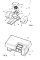
- an electrical current sensor 2 for measuring a primary current I p in a primary conductor 1 comprises a magnetic circuit 3 and a magnetic field sensor 4, 104, 204, 304.
- the magnetic circuit 3 comprises a magnetic core 5 of a magnetically permeable material and is provided with an air-gap 6 between end faces 27a, 27b in which the magnetic field sensor 4, 104, 204, 304 is positioned.
- the magnetic core 5 is shown as a generally annular-shaped part with a central opening 7, through which the primary conductor 1 extends.
- Other magnetic circuit shapes could however be provided, such as rectangular, polygonal, toroidal or otherwise, without departing from the scope of this invention.
- the primary conductor 1 is shown as extending through the magnetic circuit, however, the primary conductor could also be provided with a number of windings or conductor portions wrapped around the magnetic circuit core 5 and extending through the opening 7.
- the magnetic material of the magnetic core 5 may be provided with the properties found in known current sensors of this general type and may have a laminated construction to reduce eddy currents.
- the end faces 27a, 27b of the magnetic core 5 advantageously each have an extension 28a, 28b at the outer periphery of the core that reduces the width of the air-gap.
- These outer extensions advantageously reduce the effect of interference by magnetic fields generated outside the current sensor by conducting the external magnetic flux along the outer periphery of the magnetic core, thus avoiding the magnetic field sensor 4, 104, 204, 304.
- extensions 29a, 29b may also be provided along the inner periphery of the magnetic core 5.
- the current sensor may have the general characteristics of an open-loop current sensor, in that there is no secondary coil or conductor for compensating the ampere turns generated by the primary conductor as found in closed-loop sensors.
- the sensor may however be provided with a secondary winding 8 around the magnetic core 5 for detecting high frequency currents by the transformer effect as shown in figure 4.
- the magnetic field sensor 4, 104, 204, 304 comprises a magnetic shield 9, 109, 209 made of a soft magnetic material and a sensing cell 10, 310 positioned in a cavity 11 of the magnetic shield 9.
- the magnetic shield 9 comprises at least two shell portions 12, 112, 212 separated by a small air-gap 20 therebetween.
- the magnetic shield 9 has a generally axisymmetric or cylindrical shape in the embodiment shown in figure 1 and is arranged such that the central axis of the cylinder is substantially in line with the magnetic flux lines extending across the current sensor air-gap 6.
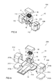
- the magnetic shield may however be provided with non-axisymmetric shapes, for example having rectangular (see figures 8 and 9), polygonal or elliptical cross-sections. It is also possible to provide the magnetic shield with a non-prismatic shape, for example as seen in the longitudinal cross section the embodiment of the magnetic shield 9 shown in Fig. 6.
- the magnetic shield 109, 209 is wholly or partially stamped and formed from sheet metal that may be annealed after forming to ensure homogeneous and optimal magnetic properties like high magnetic permeability and low coercive force.
- the stamping and forming of the magnetic shield in high volumes is particularly cost effective compared to machined shields.
- the air-gap 20 may be filled with a material having a low permeability (in other words a non-magnetic material).
- the air-gap comprises a material, such as solder or adhesive, for bonding the pair of shell parts 12, 112, 212 together.
- a longitudinal slot 13, 113, 213 extending essentially parallel to the axis of the magnetic field sensor is provided in the magnetic shield 9, 109, 209, 309 and serves to reduce Eddy currents in the soft magnetic shield.
- the slot may also serve as a passage into the magnetic shield for a conducting member 14, 214 for connection to the sensing cell 10, 310.
- the slot 213 is provided by the separation of the magnetic shield shell parts into first and second portions 212a and 212b that are assembled on opposing sides of a substrate of the conducting member 214.
- the thickness of the substrate thus defines the width of the longditudinal slot 213.
- the conducting member 14 may be in the form of a flexible printed circuit with conductive tracks 15 for connecting an electronic circuit 21 (see Fig. 7) for processing the sensor signals to the magnetic field sensing cell 10, 310.
- the printed circuit may also be provided with metallized portions 15a for soldering the portions 212a and 212b of the magnetic shield parts thereto.
- the portions of the magnetic shield parts could however also be bonded to the conducting member with an adhesive or fixed by mechanical means.
- the magnetic field sensing cell 10, 310 comprises a coil 16 and a saturable soft magnetic core 17, 317.
- the coil 16 is mounted on a bobbin 18 provided with a groove 19 or cavity 319 in which the soft magnetic core 17, 317 is mounted.
- the coil 16 is made of an insulated electrical wire electrically connected at its extremities to respective conductive tracks 15 of the conducting member 14, 214.
- the coil and bobbin may be partially overmoulded with a casing 30, that serves not only to protect the coil, but also to position the sensing cell within the cavity of the magnetic shield.
- the soft magnetic core 17, 117, 217 is advantageously made of a fine ribbon of a soft-magnetic material with a thickness preferably below 0.1 mm.
- the ribbon 17, 117, 217 may have a cross section that varies over its length, as shown in the different variants of figures 3a to 3c, in order to achieve magnetic induction values that are essentially constant all over its volume, which aids to saturate the ribbon in a very abrupt manner and leads to a current threshold for the saturation of the fluxgate that can easily be detected by the associated electronic circuit.
- the soft magnetic core 317 could be made also of a plurality of very fine wires made of soft magnetic material, bundled or bonded together to form a generally cylindrical shape, positioned in a cavity 319 of the bobbin 318.
- the wires are very thin, for example having diameters in the range of 10 to 50 microns, for example 30 microns, and bonded together with a dielectric material in order to minimize Eddy currents. This enables the sensing cell 310 to operate at very high frequencies without loss of linearity.
- the magnetic field sensing cell 10, 310 described above is operated in a similar manner to known fluxgate sensors.
- fluxgate sensors may be controlled by an electronic circuit to determine the value of the induction to be measured, such techniques also being applicable to control the magnetic field sensing cell according to this invention.
- Fluxgate sensors are very stable and precise, and have a low offset drift and gain.
- the main disadvantage of fluxgate sensors is however that they have a low magnetic induction operating range, usually in the order of only a few milli-Teslas, and are therefore not found in electrical current sensors with large magnetic fields.
- this problem is overcome by placing the magnetic field sensing cell 10, 310 in the magnetic shield 9, 109, 209 with air-gap 20, that acts as an induction divider.
- the magnetic shield 9, 109, 209 conducts most of the magnetic flux, the proportion depending on the width of the air-gap 20 between the shell parts 12, 112, 212.
- the magnetic induction inside the shield is directly proportional to the magnetic induction present in the soft magnetic material of the shield, however of a significantly lower value.
- the magnetic field sensor 4, 104, 204, 304 can be used to measure magnetic inductions as large as 100 to 200 mT, while benefiting from the precision and stability, and the absence of offset and gain drift, of a fluxgate sensing cell.
- a fluxgate sensor instead of a fluxgate sensor, it is possible to employ other types of sensitive magnetic field sensing cells that also exhibit low temperature offset and gain drift. Examples of other such magnetic field sensing cells that may be used in the present invention, are so called giant magnetoimpedance sensors or magnetoresistive sensors of any kind.
- the magnetic field sensor according to this invention may be employed not only to measure magnetic induction in an air-gap of a current sensor, but also to measure magnetic induction in other applications, such as magnetic induction generated in transducers, for example position sensors, proximity switches or encoders, and other magnetic field systems.
- FIG. 7 an example of a current sensor according to this invention for use in an integrated power module (IPM) is shown.
- the current sensor is shown mounted on a substrate of a circuit board 22, which may for example be of a ceramic material with conductive tracks thereon.
- the magnetic circuit 3 is fixed directly on the circuit board 22 and surrounds a primary conductor bar 1 that extends therethrough.
- the magnetic field sensor which may have the construction of any of the aforementioned embodiments 4, 104, 204, 304, may also be bonded directly on the printed circuit board, whereby the flexible circuit 14 thereof is conductively connected to conductive traces that connect the magnetic field sensor to an ASIC 23 for processing the sensor input and output signals.
- External connections to the circuit board may be provided via a connector 24 mounted on the circuit board and pluggable to a complementary cable connector 25.
- Conductors of the secondary winding 8 are, in this embodiment, in the form of U-shape wires 26 positioned over portions of the magnetic core 5 and bonded onto circuit traces of the circuit board 22.
- the secondary coil circuit traces pass underneath the magnetic core 5 so as to form, with the U-shape wires, essentially a coil surrounding the magnetic core.
- a particularly compact and resistant current sensor in particular to high operating temperatures, is provided.
Landscapes
- Physics & Mathematics (AREA)
- General Physics & Mathematics (AREA)
- Condensed Matter Physics & Semiconductors (AREA)
- Measuring Instrument Details And Bridges, And Automatic Balancing Devices (AREA)
- Measuring Magnetic Variables (AREA)
Priority Applications (8)
| Application Number | Priority Date | Filing Date | Title |
|---|---|---|---|
| EP03003879A EP1450176A1 (de) | 2003-02-21 | 2003-02-21 | Magnetfeldsensor und Strommesser |
| CNB2004800047002A CN100485407C (zh) | 2003-02-21 | 2004-02-18 | 磁场传感器以及其电流传感器 |
| US10/545,984 US7622909B2 (en) | 2003-02-21 | 2004-02-18 | Magnetic field sensor and electrical current sensor therewith |
| JP2006502482A JP5062877B2 (ja) | 2003-02-21 | 2004-02-18 | 磁界センサー |
| PCT/IB2004/000580 WO2004074860A1 (en) | 2003-02-21 | 2004-02-18 | Magnetic field sensor and electrical current sensor therewith |
| EP04712122.3A EP1595158B1 (de) | 2003-02-21 | 2004-02-18 | Magnetfeldsensor und strommesser |
| US12/459,691 US7969140B2 (en) | 2003-02-21 | 2009-07-07 | Magnetic field sensor and electrical current sensor therewith |
| JP2010174105A JP2010243512A (ja) | 2003-02-21 | 2010-08-03 | 電流センサー |
Applications Claiming Priority (1)
| Application Number | Priority Date | Filing Date | Title |
|---|---|---|---|
| EP03003879A EP1450176A1 (de) | 2003-02-21 | 2003-02-21 | Magnetfeldsensor und Strommesser |
Publications (1)
| Publication Number | Publication Date |
|---|---|
| EP1450176A1 true EP1450176A1 (de) | 2004-08-25 |
Family
ID=32731555
Family Applications (2)
| Application Number | Title | Priority Date | Filing Date |
|---|---|---|---|
| EP03003879A Withdrawn EP1450176A1 (de) | 2003-02-21 | 2003-02-21 | Magnetfeldsensor und Strommesser |
| EP04712122.3A Expired - Lifetime EP1595158B1 (de) | 2003-02-21 | 2004-02-18 | Magnetfeldsensor und strommesser |
Family Applications After (1)
| Application Number | Title | Priority Date | Filing Date |
|---|---|---|---|
| EP04712122.3A Expired - Lifetime EP1595158B1 (de) | 2003-02-21 | 2004-02-18 | Magnetfeldsensor und strommesser |
Country Status (5)
| Country | Link |
|---|---|
| US (2) | US7622909B2 (de) |
| EP (2) | EP1450176A1 (de) |
| JP (2) | JP5062877B2 (de) |
| CN (1) | CN100485407C (de) |
| WO (1) | WO2004074860A1 (de) |
Cited By (18)
| Publication number | Priority date | Publication date | Assignee | Title |
|---|---|---|---|---|
| EP1632783A1 (de) * | 2004-09-03 | 2006-03-08 | LG Electronics Inc. | Magnetischer Fühler zur Kurzschluss-Ortung zwischen Leiterdrähten eines Mikromusters mit hoher Dichte |
| EP1762852A2 (de) | 2005-08-25 | 2007-03-14 | Lisa Dräxlmaier GmbH | Vorrichtung und Verfahren zur Messung eines in einem elektrischen Leiter fliessenden Stromes |
| EP1879036A1 (de) * | 2006-07-14 | 2008-01-16 | Lisa Dräxlmaier GmbH | Vorrichtung und Verfahren zur Messung eines Stromflusses in einem elektrischen Leiter |
| US7365535B2 (en) | 2005-11-23 | 2008-04-29 | Honeywell International Inc. | Closed-loop magnetic sensor system |
| WO2008145686A1 (de) * | 2007-06-01 | 2008-12-04 | Epcos Ag | Anordnung zur messung eines in einem elektrischen leiter fliessenden stroms |
| WO2009019252A1 (de) * | 2007-08-03 | 2009-02-12 | Epcos Ag | Anordnung und verfahren zur messung eines in einem elektrischen leiter fliessenden stroms |
| FR2920881A1 (fr) * | 2007-09-10 | 2009-03-13 | Socomec Sa Sa | DISPOSITIF DE MESURE DE l'INTENSITE D'UN COURANT ELECTRIQUE ET APPAREIL ELECTRIQUE COMPORTANT UN TEL DISPOSITIF. |
| US7579825B2 (en) | 2006-07-14 | 2009-08-25 | Lisa Dräxlmaier GmbH | Device and method for measuring a current flowing in an electrical conductor |
| CN101838927A (zh) * | 2010-05-21 | 2010-09-22 | 中纺标(北京)检验认证中心有限公司 | 纺织品表面磁感应强度的测试装置及测试方法 |
| EP2423693A1 (de) * | 2010-08-24 | 2012-02-29 | Liaisons Electroniques-Mecaniques Lem S.A. | Ringförmiger Fluxgate-Stromwandler |
| EP3086129A1 (de) * | 2015-04-24 | 2016-10-26 | Sumida Corporation | Stromdetektor |
| EP2551680A3 (de) * | 2011-07-28 | 2017-12-06 | Vaccumschmelze Gmbh & Co. KG | Stromsensoranordnung |
| EP3140665A4 (de) * | 2014-05-06 | 2018-01-24 | Molex, LLC | Modul mit integralem sensor |
| EP3240120A3 (de) * | 2016-04-29 | 2018-01-24 | Deere & Company | Elektrische steckverbinderanordnung |
| RU197484U1 (ru) * | 2020-01-09 | 2020-04-30 | Акционерное общество "Научно-исследовательский институт командных приборов" | Датчик феррозондовый в магнитном экране |
| EP3699605A1 (de) * | 2019-02-20 | 2020-08-26 | Samsung SDI Co., Ltd. | Batteriemanagementeinheit mit in der leiterplatte integriertem fluxgate-stromsensor |
| DE102021201042B3 (de) | 2021-02-04 | 2022-01-27 | Robert Bosch Gesellschaft mit beschränkter Haftung | Magnetfeldsensorvorrichtung und Verfahren zum Herstellen einer Magnetfeldsensorvorrichtung |
| EP4617679A1 (de) * | 2024-03-15 | 2025-09-17 | Allegro MicroSystems, LLC | Kernbasierte stromsensoren mit integrierten kompensationsspulen |
Families Citing this family (81)
| Publication number | Priority date | Publication date | Assignee | Title |
|---|---|---|---|---|
| EP1450176A1 (de) * | 2003-02-21 | 2004-08-25 | Liaisons Electroniques-Mecaniques Lem S.A. | Magnetfeldsensor und Strommesser |
| EP2717295B1 (de) | 2003-12-03 | 2018-07-18 | Nikon Corporation | Belichtungsvorrichtung, Belichtungsverfahren, und Verfahren zur Herstellung einer Vorrichtung |
| JP4597797B2 (ja) * | 2005-07-06 | 2010-12-15 | 東日本旅客鉄道株式会社 | トロリ線電流検出装置 |
| JP2007121239A (ja) * | 2005-10-31 | 2007-05-17 | Denso Corp | 電流センサ及びその製造方法 |
| JP4612554B2 (ja) * | 2006-02-16 | 2011-01-12 | 株式会社東海理化電機製作所 | 電流センサ |
| SG10201507256WA (en) | 2006-08-31 | 2015-10-29 | Nikon Corp | Movable Body Drive Method And Movable Body Drive System, Pattern Formation Method And Apparatus, Exposure Method And Apparatus, And Device Manufacturing Method |
| JP4479758B2 (ja) * | 2007-07-05 | 2010-06-09 | 株式会社デンソー | 電流センサ用コア |
| DE102008012665A1 (de) * | 2008-03-05 | 2009-09-10 | Conti Temic Microelectronic Gmbh | Strommessvorrichtung mittels magnetempfindlichem Sensor für ein leistungselektronisches System |
| US8436260B2 (en) * | 2008-07-29 | 2013-05-07 | Cts Corporation | Coil retention assembly for electronic assembly |
| DE202010000328U1 (de) * | 2009-03-12 | 2010-05-20 | Liaisons Electroniques-Mécaniques LEM S.A. | Elektrischer Stromsensor |
| US20110006763A1 (en) * | 2009-07-07 | 2011-01-13 | Anthonius Bakker | Hall effect current sensor system and associated flip-chip packaging |
| US8081491B2 (en) * | 2009-07-22 | 2011-12-20 | De Geus Brent W | External neutral current sensor matched to a circuit breaker |
| EP2284549A1 (de) * | 2009-08-11 | 2011-02-16 | Liaisons Electroniques-Mècaniques LEM S.A. | Mischmodus-Fluxgate-Stromwandler |
| JP5414420B2 (ja) * | 2009-08-21 | 2014-02-12 | ジェコー株式会社 | 電流センサ及びその製造方法 |
| JP2011064648A (ja) * | 2009-09-18 | 2011-03-31 | Tokai Rika Co Ltd | 電流センサ |
| EP2520945B1 (de) * | 2009-12-28 | 2016-06-01 | TDK Corporation | Magnetfelderkennungsvorrichtung und stromsensor |
| FR2955395B1 (fr) * | 2010-01-21 | 2012-02-03 | Commissariat Energie Atomique | Detection d'etat d'equipements electriques d'un vehicule |
| US20120217963A1 (en) * | 2010-03-31 | 2012-08-30 | Omron Corporation | Magnetic core, current sensor provided with the magnetic core, and current measuring method |
| US8638092B2 (en) | 2010-08-06 | 2014-01-28 | Honeywell International, Inc. | Current sensor |
| US9121885B2 (en) * | 2010-08-16 | 2015-09-01 | Infineon Technologies Ag | Sensor package and method of manufacturing thereof |
| JP5533441B2 (ja) * | 2010-08-26 | 2014-06-25 | 株式会社オートネットワーク技術研究所 | 電流検出装置及びその製造方法 |
| EP2431751A1 (de) * | 2010-09-21 | 2012-03-21 | Liaisons Electroniques-Mecaniques Lem S.A. | Kompensations-Stromwandler mit Schaltverstärker |
| DE102011102978B4 (de) * | 2011-05-23 | 2018-05-17 | Phoenix Contact Gmbh & Co. Kg | Strommessumformer |
| CH705027A1 (de) * | 2011-05-30 | 2012-11-30 | Melexis Technologies Nv | Vorrichtung zur Messung eines durch ein elektrisches Kabel fliessenden Stroms. |
| JP5482736B2 (ja) * | 2011-06-28 | 2014-05-07 | 株式会社デンソー | 電流センサ |
| DE102011080034A1 (de) * | 2011-07-28 | 2013-01-31 | Vacuumschmelze Gmbh & Co. Kg | Stromsensoranordnung |
| JP2013044543A (ja) * | 2011-08-22 | 2013-03-04 | Denso Corp | 磁束のゼロ点検出装置 |
| CN103002649B (zh) * | 2011-09-13 | 2016-09-14 | 中微半导体设备(上海)有限公司 | 一种电感耦合式的等离子体处理装置及其基片处理方法 |
| EP2587268A1 (de) * | 2011-10-26 | 2013-05-01 | LEM Intellectual Property SA | Elektrischer Stromwandler |
| JP6131588B2 (ja) * | 2011-12-27 | 2017-05-24 | 株式会社デンソー | 電流センサ |
| CN202711934U (zh) * | 2012-01-19 | 2013-01-30 | 邹高芝 | 全pcb安装式高精度闭环型霍尔电流传感器用轴对称磁路磁芯线圈组件 |
| JP2013148512A (ja) * | 2012-01-20 | 2013-08-01 | Aisin Seiki Co Ltd | 電流センサ |
| JP5909822B2 (ja) * | 2012-02-27 | 2016-04-27 | アルプス・グリーンデバイス株式会社 | 電流センサ及びその作製方法 |
| ES2443566B1 (es) * | 2012-07-19 | 2014-12-04 | Wavecontrol, S. L. | Sensor isótropo de campos magnético y eléctrico |
| EP2690450B1 (de) * | 2012-07-27 | 2014-07-09 | ABB Technology AG | Vorrichtung zum Messen der Direktkomponente von Wechselstrom |
| CN102798828A (zh) * | 2012-08-06 | 2012-11-28 | 中国地质科学院地球物理地球化学勘查研究所 | 频率域感应式磁场传感器 |
| WO2014026702A1 (de) * | 2012-08-17 | 2014-02-20 | Klaus Bruchmann Gmbh | Baugruppe für eine schaltersicherungsanordnung mit messvorrichtung sowie sicherungshalter für eine baugruppe oder eine schaltersicherungsanordnung |
| WO2014036731A1 (en) * | 2012-09-10 | 2014-03-13 | Honeywell International Inc. | Magnetic core for sensor |
| ES2405837B1 (es) * | 2012-11-12 | 2013-10-18 | Premo, S.L. | Dispositivo sensor de corriente de montaje superficial |
| JP6372969B2 (ja) * | 2012-12-03 | 2018-08-15 | 矢崎総業株式会社 | 電流センサ |
| JP6127499B2 (ja) * | 2012-12-20 | 2017-05-17 | アイシン精機株式会社 | 電流センサ |
| JP2014190762A (ja) * | 2013-03-26 | 2014-10-06 | Toyota Industries Corp | 電流センサ |
| DE102013103350A1 (de) * | 2013-04-04 | 2014-10-09 | Weidmüller Interface GmbH & Co. KG | Stromwandler und Verfahren zum Wandeln eines in einem elektrischen Leiter fließenden Leiterstroms in ein Ausgangssignal |
| US9678173B2 (en) | 2013-05-03 | 2017-06-13 | Infineon Technologies Ag | Power module with integrated current sensor |
| US10031166B2 (en) | 2013-09-30 | 2018-07-24 | Lynary Enterprises Inc. | Electrical current measuring apparatus and method |
| CN103576030B (zh) * | 2013-11-12 | 2016-03-30 | 国家电网公司 | 一种变压器在线监测传感器 |
| US9507005B2 (en) * | 2014-03-05 | 2016-11-29 | Infineon Technologies Ag | Device and current sensor for providing information indicating a safe operation of the device of the current sensor |
| US9693488B2 (en) | 2015-02-13 | 2017-06-27 | Deere & Company | Electronic assembly with one or more heat sinks |
| US9860987B2 (en) | 2015-02-13 | 2018-01-02 | Deere & Company | Electronic assembly with one or more heat sinks |
| US10878997B2 (en) | 2015-03-13 | 2020-12-29 | Taiwan Semiconductor Manufacturing Company, Ltd. | Integrated circuit having current-sensing coil |
| EP3093672B1 (de) * | 2015-05-09 | 2020-08-12 | LEM International SA | Stromwandler mit integrierter primärer leiterschiene |
| US11175161B2 (en) * | 2016-02-23 | 2021-11-16 | Mediatek Inc. | Inductive sensor for position/orientation sensing |
| US9859624B2 (en) * | 2016-04-29 | 2018-01-02 | Deere & Company | Electrical connector assembly |
| EP3306325B1 (de) * | 2016-10-05 | 2021-07-21 | Fico Triad, S.A. | Strommessvorrichtung |
| JP6544338B2 (ja) * | 2016-11-01 | 2019-07-17 | トヨタ自動車株式会社 | 電流センサ |
| CN106653339B (zh) * | 2016-11-29 | 2019-08-02 | 杭州海兴电力科技股份有限公司 | 电流互感器 |
| EP3376238A1 (de) * | 2017-03-16 | 2018-09-19 | LEM Intellectual Property SA | Stromwandler mit magnetfeldgradientensensor |
| CN107013740A (zh) * | 2017-05-11 | 2017-08-04 | 闫化存 | 一种磁控传感器 |
| JP6522048B2 (ja) * | 2017-05-31 | 2019-05-29 | 本田技研工業株式会社 | 電力装置及び電力装置の製造方法 |
| CN107132495A (zh) * | 2017-06-21 | 2017-09-05 | 中国人民解放军国防科学技术大学 | 一种非晶丝与线圈分离的gmi传感器探头 |
| CN112119316A (zh) * | 2017-10-02 | 2020-12-22 | Abb瑞士股份有限公司 | 用于电力线设备的通量吸收器 |
| WO2019072421A1 (de) * | 2017-10-12 | 2019-04-18 | Sensitec Gmbh | Stromsensoranordnung |
| US10466314B2 (en) * | 2018-02-15 | 2019-11-05 | Hamilton Sundstrand Corporation | Integrated current sensor |
| US11579172B2 (en) * | 2018-09-26 | 2023-02-14 | Solaredge Technologies Ltd. | Flux gate sensor circuit |
| US10699976B1 (en) | 2019-01-29 | 2020-06-30 | Infineon Technologies Ag | Semiconductor module with external power sensor |
| TWI699537B (zh) * | 2019-05-23 | 2020-07-21 | 威剛科技股份有限公司 | 電流感測模組及其電流感測結構 |
| CN111983285A (zh) * | 2019-05-23 | 2020-11-24 | 威刚科技股份有限公司 | 电流传感模块及其电流传感结构 |
| CN110619997B (zh) * | 2019-07-08 | 2020-11-20 | 河南平高电气股份有限公司 | 一种电压互感器及其屏蔽罩 |
| CN110907867B (zh) * | 2019-12-13 | 2022-03-22 | 中国人民解放军国防科技大学 | 一种用于巨磁阻抗传感器的磁聚焦装置及巨磁阻抗传感器 |
| CN113125831B (zh) * | 2019-12-31 | 2025-07-15 | 新纳传感系统有限公司 | 具有双厚度导体的电流传感器 |
| DE102021105566A1 (de) | 2020-03-24 | 2021-09-30 | Honeywell International Inc. | Drehgeber |
| DE102020127623B4 (de) * | 2020-10-20 | 2022-07-07 | Vacuumschmelze Gmbh & Co. Kg | Spulenanordnung für kompensationsstromsensor |
| CN112526415B (zh) * | 2020-11-27 | 2022-02-11 | 北京航空航天大学 | 一种基于线性调频信号的磁屏蔽系数快速测量方法及装置 |
| DE102021114943A1 (de) | 2021-06-10 | 2022-12-15 | Infineon Technologies Ag | Sensorvorrichtungen mit Weichmagneten und zugehörige Herstellungsverfahren |
| DE102021207128A1 (de) | 2021-07-07 | 2023-01-12 | Zf Friedrichshafen Ag | Elektrische Einrichtung für ein Kraftfahrzeug |
| JP7800366B2 (ja) * | 2021-11-16 | 2026-01-16 | 株式会社デンソー | 電流センサ |
| CN117310265A (zh) * | 2022-06-20 | 2023-12-29 | 霍尼韦尔国际公司 | 电流传感器设备 |
| DE102023116476A1 (de) * | 2023-06-22 | 2024-12-24 | Vacuumschmelze Gmbh & Co. Kg | Polschuh-formung |
| CN116539942A (zh) * | 2023-07-06 | 2023-08-04 | 深圳市知用电子有限公司 | 磁通检测系统与电流传感器 |
| CN117961367B (zh) * | 2023-12-15 | 2024-05-28 | 天津市三鑫阳光工贸有限公司 | 一种金属外壳焊接装置 |
| CN120870642A (zh) * | 2024-04-29 | 2025-10-31 | 比亚迪股份有限公司 | 电流检测装置、功率模块以及用电设备 |
Citations (4)
| Publication number | Priority date | Publication date | Assignee | Title |
|---|---|---|---|---|
| US4362990A (en) * | 1979-04-20 | 1982-12-07 | Lgz Landis & Gyr Zug Ag | Current- and voltage-measurement transducer |
| US5180970A (en) * | 1992-02-10 | 1993-01-19 | Honeywell Inc. | Mechanically adjustable current sensor and method for making same |
| US5552700A (en) * | 1994-09-30 | 1996-09-03 | Stanley Electric Co., Ltd. | Current detecting device with a core having an integrally fixed engaging member |
| US6323636B1 (en) * | 1997-07-04 | 2001-11-27 | Liaisons Electroniques-Mecaniques Lem S.A. | Electric current pick-up shoe |
Family Cites Families (34)
| Publication number | Priority date | Publication date | Assignee | Title |
|---|---|---|---|---|
| US4059798A (en) * | 1976-03-08 | 1977-11-22 | F. W. Bell, Inc. | Method and apparatus for measuring the current flowing in a workpiece |
| US4262275A (en) * | 1980-03-27 | 1981-04-14 | International Business Machines Corporation | Hall effect apparatus for flux concentrator assembly therefor |
| US4454553A (en) * | 1980-08-29 | 1984-06-12 | Aisin Seiki Company, Limited | D.C. Current detector |
| JPS58117718A (ja) * | 1981-12-30 | 1983-07-13 | Aisin Seiki Co Ltd | 電気パルス発生器 |
| US4486279A (en) * | 1983-05-12 | 1984-12-04 | Westinghouse Electric Corp. | Apparatus and method for making a laminated core |
| CH662000A5 (fr) * | 1985-02-05 | 1987-08-31 | Lem Sa | Transformateur d'intensite pour courant continu et alternatif. |
| JPS63195518A (ja) * | 1987-02-06 | 1988-08-12 | Toyota Autom Loom Works Ltd | 圧縮機における回転検出装置 |
| JPH0185683U (de) * | 1987-11-28 | 1989-06-07 | ||
| JPH02309274A (ja) * | 1989-05-25 | 1990-12-25 | Fujitsu Ltd | 磁気インクパターン検出器及び磁気抵抗素子搭載方法 |
| JPH086297Y2 (ja) * | 1989-10-09 | 1996-02-21 | 株式会社トーキン | 電流検出器 |
| JPH04125981A (ja) * | 1990-09-18 | 1992-04-27 | Fujitsu Ltd | Squid磁束計 |
| JPH0526906A (ja) * | 1991-07-23 | 1993-02-05 | Secoh Giken Inc | 電流検出装置 |
| JP2704483B2 (ja) * | 1993-03-31 | 1998-01-26 | スタンレー電気株式会社 | 電流検出装置 |
| US5430613A (en) * | 1993-06-01 | 1995-07-04 | Eaton Corporation | Current transformer using a laminated toroidal core structure and a lead frame |
| CN2194006Y (zh) * | 1994-07-25 | 1995-04-05 | 徐叔炎 | 电流传感器 |
| JP3545074B2 (ja) * | 1994-12-27 | 2004-07-21 | 独立行政法人 科学技術振興機構 | 半導体基板に集積される磁気検出素子及び磁気検出モジュール |
| US5619240A (en) * | 1995-01-31 | 1997-04-08 | Tektronix, Inc. | Printer media path sensing apparatus |
| JPH08285899A (ja) * | 1995-04-18 | 1996-11-01 | Shimadzu Corp | 交流大電流に重畳する三角波の測定方法及び交流大電流に重畳する直流分の測定方法 |
| FR2747196B1 (fr) * | 1996-04-05 | 1998-06-26 | Magneti Marelli France | Dispositif moteur a commande electromagnetique, notamment logometre |
| JP3840311B2 (ja) * | 1997-06-04 | 2006-11-01 | Smk株式会社 | 電磁シールド構造 |
| DE19741417B4 (de) * | 1997-09-19 | 2004-02-26 | Klaus Bruchmann | Strommessgerät mit Hallsensor |
| TW434411B (en) * | 1998-10-14 | 2001-05-16 | Tdk Corp | Magnetic sensor apparatus, current sensor apparatus and magnetic sensing element |
| WO2000043795A1 (en) * | 1999-01-21 | 2000-07-27 | Tdk Corporation | Current sensor |
| US6426617B1 (en) * | 1999-09-28 | 2002-07-30 | Rockwell Automation Technologies, Inc. | Hall effect current sensor system packaging |
| DE10104453A1 (de) * | 2001-02-01 | 2002-08-08 | Philips Corp Intellectual Pty | Anordnung zum Messen der magnetischen Feldstärke |
| DE10110475A1 (de) * | 2001-03-05 | 2002-09-26 | Vacuumschmelze Gmbh & Co Kg | Übertrager für einen Stromsensor |
| JP2002288807A (ja) * | 2001-03-28 | 2002-10-04 | Canon Electronics Inc | 磁気ヘッドの製造方法及び磁気ヘッド |
| JP4164626B2 (ja) * | 2001-06-15 | 2008-10-15 | サンケン電気株式会社 | ホ−ル素子を備えた電流検出装置 |
| JP2003017347A (ja) * | 2001-07-04 | 2003-01-17 | Tamura Seisakusho Co Ltd | 電流センサ |
| US6642704B2 (en) * | 2001-09-28 | 2003-11-04 | Eaton Corporation | Device for sensing electrical current and housing therefor |
| US6570373B1 (en) * | 2002-03-07 | 2003-05-27 | Visteon Global Technologies, Inc. | Current sensor programmable through connector |
| KR100464098B1 (ko) * | 2002-03-14 | 2005-01-03 | 삼성전기주식회사 | 인쇄회로기판에 집적된 자계검출소자 및 그 제조방법 |
| US6759840B2 (en) * | 2002-06-11 | 2004-07-06 | Rockwell Automation Technologies, Inc. | Hall effect conductor/core method and apparatus |
| EP1450176A1 (de) * | 2003-02-21 | 2004-08-25 | Liaisons Electroniques-Mecaniques Lem S.A. | Magnetfeldsensor und Strommesser |
-
2003
- 2003-02-21 EP EP03003879A patent/EP1450176A1/de not_active Withdrawn
-
2004
- 2004-02-18 EP EP04712122.3A patent/EP1595158B1/de not_active Expired - Lifetime
- 2004-02-18 WO PCT/IB2004/000580 patent/WO2004074860A1/en not_active Ceased
- 2004-02-18 CN CNB2004800047002A patent/CN100485407C/zh not_active Expired - Lifetime
- 2004-02-18 US US10/545,984 patent/US7622909B2/en not_active Expired - Fee Related
- 2004-02-18 JP JP2006502482A patent/JP5062877B2/ja not_active Expired - Fee Related
-
2009
- 2009-07-07 US US12/459,691 patent/US7969140B2/en active Active
-
2010
- 2010-08-03 JP JP2010174105A patent/JP2010243512A/ja active Pending
Patent Citations (4)
| Publication number | Priority date | Publication date | Assignee | Title |
|---|---|---|---|---|
| US4362990A (en) * | 1979-04-20 | 1982-12-07 | Lgz Landis & Gyr Zug Ag | Current- and voltage-measurement transducer |
| US5180970A (en) * | 1992-02-10 | 1993-01-19 | Honeywell Inc. | Mechanically adjustable current sensor and method for making same |
| US5552700A (en) * | 1994-09-30 | 1996-09-03 | Stanley Electric Co., Ltd. | Current detecting device with a core having an integrally fixed engaging member |
| US6323636B1 (en) * | 1997-07-04 | 2001-11-27 | Liaisons Electroniques-Mecaniques Lem S.A. | Electric current pick-up shoe |
Cited By (30)
| Publication number | Priority date | Publication date | Assignee | Title |
|---|---|---|---|---|
| EP1632783A1 (de) * | 2004-09-03 | 2006-03-08 | LG Electronics Inc. | Magnetischer Fühler zur Kurzschluss-Ortung zwischen Leiterdrähten eines Mikromusters mit hoher Dichte |
| EP1762852A2 (de) | 2005-08-25 | 2007-03-14 | Lisa Dräxlmaier GmbH | Vorrichtung und Verfahren zur Messung eines in einem elektrischen Leiter fliessenden Stromes |
| EP1762852A3 (de) * | 2005-08-25 | 2008-12-17 | Lisa Dräxlmaier GmbH | Vorrichtung und Verfahren zur Messung eines in einem elektrischen Leiter fliessenden Stromes |
| US7365535B2 (en) | 2005-11-23 | 2008-04-29 | Honeywell International Inc. | Closed-loop magnetic sensor system |
| US7579825B2 (en) | 2006-07-14 | 2009-08-25 | Lisa Dräxlmaier GmbH | Device and method for measuring a current flowing in an electrical conductor |
| EP1879036A1 (de) * | 2006-07-14 | 2008-01-16 | Lisa Dräxlmaier GmbH | Vorrichtung und Verfahren zur Messung eines Stromflusses in einem elektrischen Leiter |
| US7923986B2 (en) | 2006-07-14 | 2011-04-12 | Lisa Draexlmaier Gmbh | Device and method for measuring a current flowing in an electrical conductor |
| WO2008145686A1 (de) * | 2007-06-01 | 2008-12-04 | Epcos Ag | Anordnung zur messung eines in einem elektrischen leiter fliessenden stroms |
| US7911197B2 (en) | 2007-06-01 | 2011-03-22 | Epcos Ag | Arrangement for measuring the current flowing in an electric conductor |
| CN101680917B (zh) * | 2007-06-01 | 2012-04-25 | 埃普科斯股份有限公司 | 用于测量在电导体中流动的电流的装置 |
| WO2009019252A1 (de) * | 2007-08-03 | 2009-02-12 | Epcos Ag | Anordnung und verfahren zur messung eines in einem elektrischen leiter fliessenden stroms |
| US8294452B2 (en) | 2007-08-03 | 2012-10-23 | Epcos Ag | Arrangement and method for measuring a current flowing in an electrical conductor |
| WO2009034440A3 (fr) * | 2007-09-10 | 2009-05-22 | Socomec Sa | Dispositif de mesure de l'intensite d'un courant electrique et appareil electrique comportant un tel dispositif |
| FR2920881A1 (fr) * | 2007-09-10 | 2009-03-13 | Socomec Sa Sa | DISPOSITIF DE MESURE DE l'INTENSITE D'UN COURANT ELECTRIQUE ET APPAREIL ELECTRIQUE COMPORTANT UN TEL DISPOSITIF. |
| US8299779B2 (en) | 2007-09-10 | 2012-10-30 | Socomec S. A. | Device for measuring the intensity of an electric current and electric appliance including such device |
| CN101838927A (zh) * | 2010-05-21 | 2010-09-22 | 中纺标(北京)检验认证中心有限公司 | 纺织品表面磁感应强度的测试装置及测试方法 |
| WO2012025859A1 (en) * | 2010-08-24 | 2012-03-01 | Liaisons Electroniques-Mecaniques Lem S.A. | Toroidal fluxgate current transducer |
| US9423469B2 (en) | 2010-08-24 | 2016-08-23 | Lem Intellectual Property Sa | Toroidal fluxgate current transducer |
| EP2423693A1 (de) * | 2010-08-24 | 2012-02-29 | Liaisons Electroniques-Mecaniques Lem S.A. | Ringförmiger Fluxgate-Stromwandler |
| EP2551680A3 (de) * | 2011-07-28 | 2017-12-06 | Vaccumschmelze Gmbh & Co. KG | Stromsensoranordnung |
| EP3140665A4 (de) * | 2014-05-06 | 2018-01-24 | Molex, LLC | Modul mit integralem sensor |
| US9939465B2 (en) | 2015-04-24 | 2018-04-10 | Sumida Corporation | Electric current detector |
| EP3086129A1 (de) * | 2015-04-24 | 2016-10-26 | Sumida Corporation | Stromdetektor |
| EP3240120A3 (de) * | 2016-04-29 | 2018-01-24 | Deere & Company | Elektrische steckverbinderanordnung |
| US10165670B2 (en) | 2016-04-29 | 2018-12-25 | Deere & Company | Electrical connector assembly |
| EP3699605A1 (de) * | 2019-02-20 | 2020-08-26 | Samsung SDI Co., Ltd. | Batteriemanagementeinheit mit in der leiterplatte integriertem fluxgate-stromsensor |
| US11280852B2 (en) | 2019-02-20 | 2022-03-22 | Samsung Sdi Co., Ltd. | Battery management unit with a PCB integrated fluxgate current sensor |
| RU197484U1 (ru) * | 2020-01-09 | 2020-04-30 | Акционерное общество "Научно-исследовательский институт командных приборов" | Датчик феррозондовый в магнитном экране |
| DE102021201042B3 (de) | 2021-02-04 | 2022-01-27 | Robert Bosch Gesellschaft mit beschränkter Haftung | Magnetfeldsensorvorrichtung und Verfahren zum Herstellen einer Magnetfeldsensorvorrichtung |
| EP4617679A1 (de) * | 2024-03-15 | 2025-09-17 | Allegro MicroSystems, LLC | Kernbasierte stromsensoren mit integrierten kompensationsspulen |
Also Published As
| Publication number | Publication date |
|---|---|
| JP2010243512A (ja) | 2010-10-28 |
| CN100485407C (zh) | 2009-05-06 |
| US7622909B2 (en) | 2009-11-24 |
| US20060226826A1 (en) | 2006-10-12 |
| JP5062877B2 (ja) | 2012-10-31 |
| WO2004074860A1 (en) | 2004-09-02 |
| JP2006518850A (ja) | 2006-08-17 |
| CN1751247A (zh) | 2006-03-22 |
| EP1595158B1 (de) | 2016-04-27 |
| EP1595158A1 (de) | 2005-11-16 |
| US7969140B2 (en) | 2011-06-28 |
| US20090295384A1 (en) | 2009-12-03 |
Similar Documents
| Publication | Publication Date | Title |
|---|---|---|
| EP1595158B1 (de) | Magnetfeldsensor und strommesser | |
| EP1546741B1 (de) | Integrierter stromsensor | |
| US7365535B2 (en) | Closed-loop magnetic sensor system | |
| CN112485495B (zh) | 电流传感器 | |
| CN101809457B (zh) | 具有被夹在中间的磁导率层的电流传感器 | |
| EP1965217B1 (de) | Stromsensor mit offenem Regelkreis und hoher Bandbreite | |
| EP1450166A1 (de) | Stromsensor | |
| CN1005931B (zh) | 测量导电体中电流的测量用变换器 | |
| US10989740B2 (en) | Closed-loop current transducer | |
| EP2960661B1 (de) | Modulares strommesssystem und verfahren zur herstellung eines modularen strommesssystems | |
| CN103123369A (zh) | 电流感应装置 | |
| JPS6395363A (ja) | 電流センサおよび被評価導体中の電流検出方法 | |
| CN120826613A (zh) | 具有差分磁场换能器的电流传感器 | |
| JP2651003B2 (ja) | 渦電流式変位センサ | |
| US11988690B2 (en) | Current transducer | |
| JPH022544B2 (de) | ||
| JP2004037354A (ja) | 電流検出装置 | |
| AU2001100615A4 (en) | Terminal arrangement for electricity meter | |
| JPH04148869A (ja) | 電流センサ | |
| WO2001033242A1 (en) | A thin magnetoresistive current sensor system | |
| CN119619603A (zh) | 一种具有柔性磁环的巨磁阻电流传感器 | |
| KR20000033216A (ko) | 소형화에 적합한 고감도 차동형 와전류 탐침 | |
| JPS63228072A (ja) | 計測器のホ−ル素子付検出装置 |
Legal Events
| Date | Code | Title | Description |
|---|---|---|---|
| PUAI | Public reference made under article 153(3) epc to a published international application that has entered the european phase |
Free format text: ORIGINAL CODE: 0009012 |
|
| AK | Designated contracting states |
Kind code of ref document: A1 Designated state(s): AT BE BG CH CY CZ DE DK EE ES FI FR GB GR HU IE IT LI LU MC NL PT SE SI SK TR |
|
| AX | Request for extension of the european patent |
Extension state: AL LT LV MK RO |
|
| AKX | Designation fees paid | ||
| REG | Reference to a national code |
Ref country code: DE Ref legal event code: 8566 |
|
| STAA | Information on the status of an ep patent application or granted ep patent |
Free format text: STATUS: THE APPLICATION IS DEEMED TO BE WITHDRAWN |
|
| 18D | Application deemed to be withdrawn |
Effective date: 20050226 |