EP1450367A1 - Dispositif et procede d'enregistrement/lecture de donnees - Google Patents
Dispositif et procede d'enregistrement/lecture de donnees Download PDFInfo
- Publication number
- EP1450367A1 EP1450367A1 EP02788605A EP02788605A EP1450367A1 EP 1450367 A1 EP1450367 A1 EP 1450367A1 EP 02788605 A EP02788605 A EP 02788605A EP 02788605 A EP02788605 A EP 02788605A EP 1450367 A1 EP1450367 A1 EP 1450367A1
- Authority
- EP
- European Patent Office
- Prior art keywords
- recording
- data
- file information
- restoration
- file
- Prior art date
- Legal status (The legal status is an assumption and is not a legal conclusion. Google has not performed a legal analysis and makes no representation as to the accuracy of the status listed.)
- Withdrawn
Links
Images


Classifications
-
- G—PHYSICS
- G11—INFORMATION STORAGE
- G11B—INFORMATION STORAGE BASED ON RELATIVE MOVEMENT BETWEEN RECORD CARRIER AND TRANSDUCER
- G11B27/00—Editing; Indexing; Addressing; Timing or synchronising; Monitoring; Measuring tape travel
- G11B27/10—Indexing; Addressing; Timing or synchronising; Measuring tape travel
- G11B27/102—Programmed access in sequence to addressed parts of tracks of operating record carriers
- G11B27/105—Programmed access in sequence to addressed parts of tracks of operating record carriers of operating discs
-
- G—PHYSICS
- G11—INFORMATION STORAGE
- G11B—INFORMATION STORAGE BASED ON RELATIVE MOVEMENT BETWEEN RECORD CARRIER AND TRANSDUCER
- G11B20/00—Signal processing not specific to the method of recording or reproducing; Circuits therefor
- G11B20/10—Digital recording or reproducing
-
- G—PHYSICS
- G11—INFORMATION STORAGE
- G11B—INFORMATION STORAGE BASED ON RELATIVE MOVEMENT BETWEEN RECORD CARRIER AND TRANSDUCER
- G11B19/00—Driving, starting, stopping record carriers not specifically of filamentary or web form, or of supports therefor; Control thereof; Control of operating function ; Driving both disc and head
- G11B19/02—Control of operating function, e.g. switching from recording to reproducing
- G11B19/04—Arrangements for preventing, inhibiting, or warning against double recording on the same blank or against other recording or reproducing malfunctions
-
- G—PHYSICS
- G11—INFORMATION STORAGE
- G11B—INFORMATION STORAGE BASED ON RELATIVE MOVEMENT BETWEEN RECORD CARRIER AND TRANSDUCER
- G11B20/00—Signal processing not specific to the method of recording or reproducing; Circuits therefor
- G11B20/10—Digital recording or reproducing
- G11B20/18—Error detection or correction; Testing, e.g. of drop-outs
-
- G—PHYSICS
- G11—INFORMATION STORAGE
- G11B—INFORMATION STORAGE BASED ON RELATIVE MOVEMENT BETWEEN RECORD CARRIER AND TRANSDUCER
- G11B27/00—Editing; Indexing; Addressing; Timing or synchronising; Monitoring; Measuring tape travel
- G11B27/10—Indexing; Addressing; Timing or synchronising; Measuring tape travel
- G11B27/19—Indexing; Addressing; Timing or synchronising; Measuring tape travel by using information detectable on the record carrier
- G11B27/28—Indexing; Addressing; Timing or synchronising; Measuring tape travel by using information detectable on the record carrier by using information signals recorded by the same method as the main recording
- G11B27/32—Indexing; Addressing; Timing or synchronising; Measuring tape travel by using information detectable on the record carrier by using information signals recorded by the same method as the main recording on separate auxiliary tracks of the same or an auxiliary record carrier
- G11B27/327—Table of contents
- G11B27/329—Table of contents on a disc [VTOC]
-
- H—ELECTRICITY
- H04—ELECTRIC COMMUNICATION TECHNIQUE
- H04N—PICTORIAL COMMUNICATION, e.g. TELEVISION
- H04N5/00—Details of television systems
- H04N5/76—Television signal recording
- H04N5/765—Interface circuits between an apparatus for recording and another apparatus
- H04N5/77—Interface circuits between an apparatus for recording and another apparatus between a recording apparatus and a television camera
- H04N5/772—Interface circuits between an apparatus for recording and another apparatus between a recording apparatus and a television camera the recording apparatus and the television camera being placed in the same enclosure
-
- G—PHYSICS
- G11—INFORMATION STORAGE
- G11B—INFORMATION STORAGE BASED ON RELATIVE MOVEMENT BETWEEN RECORD CARRIER AND TRANSDUCER
- G11B20/00—Signal processing not specific to the method of recording or reproducing; Circuits therefor
- G11B20/10—Digital recording or reproducing
- G11B2020/10935—Digital recording or reproducing wherein a time constraint must be met
- G11B2020/10972—Management of interruptions, e.g. due to editing
-
- G—PHYSICS
- G11—INFORMATION STORAGE
- G11B—INFORMATION STORAGE BASED ON RELATIVE MOVEMENT BETWEEN RECORD CARRIER AND TRANSDUCER
- G11B2220/00—Record carriers by type
- G11B2220/20—Disc-shaped record carriers
- G11B2220/21—Disc-shaped record carriers characterised in that the disc is of read-only, rewritable, or recordable type
- G11B2220/215—Recordable discs
- G11B2220/216—Rewritable discs
-
- G—PHYSICS
- G11—INFORMATION STORAGE
- G11B—INFORMATION STORAGE BASED ON RELATIVE MOVEMENT BETWEEN RECORD CARRIER AND TRANSDUCER
- G11B2220/00—Record carriers by type
- G11B2220/20—Disc-shaped record carriers
- G11B2220/21—Disc-shaped record carriers characterised in that the disc is of read-only, rewritable, or recordable type
- G11B2220/215—Recordable discs
- G11B2220/218—Write-once discs
-
- G—PHYSICS
- G11—INFORMATION STORAGE
- G11B—INFORMATION STORAGE BASED ON RELATIVE MOVEMENT BETWEEN RECORD CARRIER AND TRANSDUCER
- G11B2220/00—Record carriers by type
- G11B2220/20—Disc-shaped record carriers
- G11B2220/25—Disc-shaped record carriers characterised in that the disc is based on a specific recording technology
- G11B2220/2525—Magneto-optical [MO] discs
-
- G—PHYSICS
- G11—INFORMATION STORAGE
- G11B—INFORMATION STORAGE BASED ON RELATIVE MOVEMENT BETWEEN RECORD CARRIER AND TRANSDUCER
- G11B2220/00—Record carriers by type
- G11B2220/20—Disc-shaped record carriers
- G11B2220/25—Disc-shaped record carriers characterised in that the disc is based on a specific recording technology
- G11B2220/2525—Magneto-optical [MO] discs
- G11B2220/2529—Mini-discs
-
- G—PHYSICS
- G11—INFORMATION STORAGE
- G11B—INFORMATION STORAGE BASED ON RELATIVE MOVEMENT BETWEEN RECORD CARRIER AND TRANSDUCER
- G11B2220/00—Record carriers by type
- G11B2220/20—Disc-shaped record carriers
- G11B2220/25—Disc-shaped record carriers characterised in that the disc is based on a specific recording technology
- G11B2220/2537—Optical discs
- G11B2220/2545—CDs
-
- G—PHYSICS
- G11—INFORMATION STORAGE
- G11B—INFORMATION STORAGE BASED ON RELATIVE MOVEMENT BETWEEN RECORD CARRIER AND TRANSDUCER
- G11B2220/00—Record carriers by type
- G11B2220/20—Disc-shaped record carriers
- G11B2220/25—Disc-shaped record carriers characterised in that the disc is based on a specific recording technology
- G11B2220/2537—Optical discs
- G11B2220/2562—DVDs [digital versatile discs]; Digital video discs; MMCDs; HDCDs
-
- G—PHYSICS
- G11—INFORMATION STORAGE
- G11B—INFORMATION STORAGE BASED ON RELATIVE MOVEMENT BETWEEN RECORD CARRIER AND TRANSDUCER
- G11B2220/00—Record carriers by type
- G11B2220/20—Disc-shaped record carriers
- G11B2220/25—Disc-shaped record carriers characterised in that the disc is based on a specific recording technology
- G11B2220/2537—Optical discs
- G11B2220/2562—DVDs [digital versatile discs]; Digital video discs; MMCDs; HDCDs
- G11B2220/2575—DVD-RAMs
-
- H—ELECTRICITY
- H04—ELECTRIC COMMUNICATION TECHNIQUE
- H04N—PICTORIAL COMMUNICATION, e.g. TELEVISION
- H04N5/00—Details of television systems
- H04N5/76—Television signal recording
- H04N5/84—Television signal recording using optical recording
- H04N5/85—Television signal recording using optical recording on discs or drums
-
- H—ELECTRICITY
- H04—ELECTRIC COMMUNICATION TECHNIQUE
- H04N—PICTORIAL COMMUNICATION, e.g. TELEVISION
- H04N9/00—Details of colour television systems
- H04N9/79—Processing of colour television signals in connection with recording
- H04N9/80—Transformation of the television signal for recording, e.g. modulation, frequency changing; Inverse transformation for playback
- H04N9/804—Transformation of the television signal for recording, e.g. modulation, frequency changing; Inverse transformation for playback involving pulse code modulation of the colour picture signal components
- H04N9/8042—Transformation of the television signal for recording, e.g. modulation, frequency changing; Inverse transformation for playback involving pulse code modulation of the colour picture signal components involving data reduction
- H04N9/8047—Transformation of the television signal for recording, e.g. modulation, frequency changing; Inverse transformation for playback involving pulse code modulation of the colour picture signal components involving data reduction using transform coding
Definitions
- the present invention relates to an apparatus and method for recording and reproducing data and a digital camera which additionally record data to a recording medium, in particular, to an apparatus and method for recording and reproducing data and a digital camera which, even though writing processing is interrupted during recording processing, can restore data before the interruption.
- optical disc As an optical recording medium which can optically read out data, a disc-shaped recording medium (referred to as optical disc, hereinafter) such as a CD (Compact Disc) has been used.
- This kind of optical disc has large storage capacity and can realize random accessing.
- an optical read-out unit In reading out data which is optically recorded on an optical disc, since an optical read-out unit is not brought into contact with an optical disc, there is caused little fear that the recording medium and optical read-out unit are caused to be worn out or damaged due to contact between the recording medium and optical read-out unit, which may be raised in the case of using a magnetic tape as a recording medium.
- an optical disc Since an optical disc has a protective layer made of synthetic resin formed on a surface thereof so as to protect the signal recording layer, there is little fear that data is lost by mistake as compared with the case using a magnetic tape. So, an optical disc which has much advantage as compared with a recording medium such as a magnetic tape is an excellent recording medium adopted for storing data processed in an information processing apparatus such as a personal computer.
- CD-R Compact Disc-Recordable
- CD-RW Compact Disc-Rewritable
- recording and reproducing apparatuses which can easily perform writing processing corresponding to all standard formats used in compact discs such as a CR-ROM, CR-ROM/XA, CD-I, CD-DA.
- a CD-R is arranged in a electronic apparatus and is used as a recording medium for recording data processed in the electronic apparatus.
- UDF Universal Disc Format
- OSTA Optical Storage Technology Association
- a recording medium conforming to the UDF employs the packet writing in writing data.
- data is written in the packet configuration in which one link block and four Run-In areas are arranged before the data area and two Run-Out areas are arranged after the data area. So, seven blocks other than the data area are used as linking recording areas (referred to as Linking Area, hereinafter) being linking areas between adjacent packets.
- management information of a directory and a file is indirectly managed using an FID (File Identifier Descriptor), a VAT (Virtual Allocation Table), a File Entry ICB (File Entry Information Control Block), etc., instead of being directly managed using a real recording position (real address).
- FID File Identifier Descriptor
- VAT Virtual Allocation Table
- ICB File Entry Information Control Block
- the VAT is a technique to manage real addresses where files are really recorded and virtual addresses corresponding to the real addresses, forming a correspondence table.
- the VAT when additionally recording data to a recording medium, the recording medium is processed as if its arbitrary address on the recording medium is accessed so as to update or reproduce data.
- VAT Position information of directories and files is indirectly referred to.
- the VAT is freely arranged in the packet configuration, while a VAT ICB (Virtual Allocation Table Information Control Block) indicating the VAT is necessarily arranged at a position returning from the final sector recorded on a recording medium by the Linking Area. So, in the UDF, virtual addresses can be converted to real addresses by reading out the VAT indicated by the VAT ICB.
- VAT ICB Virtual Allocation Table Information Control Block
- a string of logical sectors in which writing/reading out of data is performed is referred to as an extent, and start addresses of respective extents are retained as file information and are additionally recorded together with file system information to be updated.
- a restoration processing which restores such unreadable data to make the data readable to a certain extent.
- a conventional restoration processing which retrieves file information forward and rerecord information in which damage is found.
- damaged data may be restored to be of the state before writing, while data which is interrupted during writing processing cannot be restored. That is, under the conventional restoration processing, once writing processing is interrupted, there is raised a problem that thus interrupted data cannot be accessed.
- the present invention has an object to provide a new apparatus and method for recording and reproducing data and a digital camera which can overcome the above-mentioned drawbacks of the conventional apparatus and method for recording and reproducing data.
- the present invention has another object to provide an apparatus and method for recording and reproducing data and a digital camera employing the method for recording and reproducing data which, even though there is raised failure in writing data, can make data before the interruption readable.
- the above object can be attained by providing an apparatus for recording and reproducing data which manages files and records and/or reproduces data based on a virtual allocation table showing correspondence between actual addresses indicative of recording positions of the files on a recording medium and virtual addresses indicative of virtual recording positions of the files, the files having a sequence of data stored therein, the apparatus including:
- the record control means records file information concerning a file including a sequence of data to a predetermined area of the recording medium as restoration file information, and when interruption of data recording processing is detected, the record control means retrieves and reads out restoration file information, and restores a file whose recording processing is interrupted based on the restoration file information.
- the above object can be attained by providing a method for recording and reproducing data which manages files and records and/or reproduces data based on a virtual allocation table showing correspondence between actual addresses indicative of recording positions of the files on a recording medium and virtual addresses indicative of virtual recording positions of the files, the files having a sequence of data stored therein, the method including:
- restoration file information record step file information concerning a file including a sequence of data is recorded to a predetermined area of the recording medium as restoration file information, and at the data record step, when interruption of data recording processing is detected, restoration file information is retrieved and read out, and a file whose recording processing is interrupted is restored based on the restoration file information.
- a digital camera including:
- the record control means records file information concerning a file including a sequence of data to a predetermined area of the recording medium as restoration file information, and when interruption of data recording processing is detected, the record control means retrieves and reads out restoration file information, and restores a file whose recording processing is interrupted based on the restoration file information.
- the digital camera employing the present invention has a driver for additionally recording a data file to a recording medium, especially to a disc-shaped recording medium such as a CD-R (Compact Disc-Recordable), CD-RW (Compact Disc-Rewritable), etc., based on a file system conforming to the UDF (Universal Disc Format), and reproducing thus recorded data file.
- the digital camera is provided with an image capturing unit and captures an object using the image capturing unit, and records thus captured image data to a recording medium.
- a digital camera employing the present invention specifically, there are a digital still camera capable of image capturing and recording a still picture and a non-compressed still picture, a digital camcorder and a digital video recorder capable of capturing and recording a moving picture, and a digital camera having these functions.
- the digital camera employing the present invention has a recording and reproducing unit, and in recording a sequence of data, the recording and reproducing unit records file information concerning a file including the sequence of data to a predetermined area of a recording medium as restoration file information or file information for restoration.
- file information concerning a file including the sequence of data to a predetermined area of a recording medium as restoration file information or file information for restoration.
- the digital camera employing the present invention restores a file by performing processing shown in FIG.1A and FIG.1B.
- step S1 the digital camera updates file information concerning a file including a sequence of data to be written as restoration file information, as shown in FIG.1A.
- step S2 thus updated restoration file information concerning a file including a sequence of data is recorded to a recording medium together with the sequence of data.
- step S3 it is judged whether or not there exists data to be recorded, and in case there is data to be recorded, the processing returns to step S1 to repeat above-described steps.
- step S4 in which the file information of the data is finally recorded and the data writing processing is completed.
- file information concerning the sequence of data is written following the data, details of which will be explained later. So, since file information and file system information are recorded to the end of the recording area, if writing processing of data object is not finished, writing processing of data to a recording medium such as an optical disc is not completed. That is, in case data writing processing to a recording medium is not completed, and file information, file system information, etc. are not written to the recording medium, the data cannot be read out.
- the digital camera employing the present invention can cope with the accident by performing restoration processing shown in FIG.1B.
- interruption of recording processing due to discontinuance of drive power supply uncovering of a cover arranged at a drive which veils a recording medium, impact, etc. is detected during the data recording step of step S2, the following restoration processing is initiated.
- step S11 shown in FIG.1B latest restoration file information which is updated in step S1 shown in FIG.1A is retrieved to be read out, and then in step S12, file information of a file which is interrupted during recording processing is restored based on the read out restoration file information. Finally, in step S13, thus restored file information is recorded following the file data whose writing processing is interrupted.
- the digital camera of the present invention can restore file information of data whose writing processing is interrupted based on restoration file information which is updated before writing data and written to a predetermined area of the recording medium, and read out data before the interruption of writing processing.
- the UDF Universal Disc Format
- the UDF is one of standards to describe character codes of file names, file attributes, etc., which are mutually usable, for various media such as a CD-R (Compact Disc-Recordable), WORM (Write-Once Read-Many Optical Disc), CD-R/RW (Compact Disc-Recordable/Rewritable), MO (Magneto Optical Disc), and DVD (Digital Versatile Disc), and is established by the OSTA (Optical Storage Technology Association). That is, the UDF is a file system adopted to enable data exchange on every operating system (OS), and the digital camera of the present embodiment employs the sequential writing system of the UDF revision 1.50.
- OS operating system
- the UDF employs a File Entry ICB (File Entry Information Control Block) as its main data structure.
- ICB File Entry Information Control Block
- each of all files and directories has a unique ICB.
- ICB File Entry Information Control Block
- each of all files and directories has a unique ICB.
- a file which stores actual data such as image data of a captured image is written before an ICB which defines the file.
- the ICB can include the list of the extents.
- each file or directory on a recording medium is directly referred to using an actual address, while in the UDF, each file or directory is referred to using above-described virtual address.
- the VAT can be arranged at any place on tracks, and the VAT can be indicated by a VAT ICB which indicates the position of the VAT.
- the VAT ICB is necessarily arranged at a position returning from the final sector recorded on a recording medium by the Linking Area.
- the VAT ICB includes an extents list of the VAT which is divisionally arranged at a plurality of extents. So, in the UDF, even though a file is changed using a certain method, all of a sequence of file pointers do not have to be changed, and it is possible to reach the changed file by changing only the final VAT ICB.
- a write-once type recording medium is treated as a rewritable type recording medium.
- a digital camera 1 employing the present invention includes an image capturing unit 10 for capturing an object, an image signal processor 11 for performing conversion processing for image signals from the image capturing unit 10, a display unit 12 for displaying operation information used to operate the digital camera 1 and image signals, an OP (Optical Pickup) unit 13 for writing and/or reading out data to and/or from a recording medium to be described later, an RF processor 14 for performing RF processing for read out signals, a servo signal processor 15 for generating servo signals using various signals from the RF processor 14, an analog filter processor 16 for generating analog signals used to control respective drivers based on signals from the servo signal processor 15, a signal processor 17 for processing read out signals from a recording medium to be described later, a spindle driver 18 for controlling rotation of a spindle motor, a thread driver 19 for controlling operation of a thread motor, a tracking driver 20 for moving an objective lens of the OP unit 13, a focus driver 21 for perpendicularly moving the objective lens of the OP unit 13 toward a disc
- the image capturing unit 10 includes a lens unit 30 for capturing an image of an object, a charge coupled device (referred to as CCD, hereinafter) 31 for generating image signals, a sample-and-hold (referred to as S/H, hereinafter) circuit 32, an A/D conversion circuit 33 for converting image signals to digital signals.
- the CCD 31 generates image signals using an image of an object from the lens unit 30, and sends thus generated image signals to the S/H circuit 32.
- the S/H circuit 32 samples and holds image signals from the CCD 31, and sends thus sampled and held image signals to the A/D conversion circuit 33.
- the A/D conversion circuit 33 converts image signals from the S/H circuit 32 to digital signals, and sends thus converted digital signals to the image signal processor 11.
- the image signal processor 11 performs image processing such as color basic form conversion from RGB signals to color difference signals and luminance signals, white balance, gamma correction, image reduction, and JPEG compression for digital image signals from the image capturing unit 10. Then, thus processed image signals are sent to the signal processor 17. Also, the image signal processor 11 sends thus processed image signals to the display unit 12.
- the display unit 12 may be an LCD (liquid crystal display) and displays image signals from the image signal processor 11.
- the OP unit 13 includes an objective lens, an LD (laser diode), a laser diode driver, a photo detect IC, a half mirror, etc., and detects optical signals and outputs thus detected optical signals to the RF processor 14.
- the OP unit 13 writes data to the recording medium 25 based on flashing and drive signals (DECEFMW) of a laser, write strategy signals indicative of the optimum value of laser intensity and blinking from the signal processor 17 necessary in forming pits.
- DECEFMW flashing and drive signals
- the RF processor 14 samples and holds eight type signals composed of beam signal, side, main detected by the OP unit 13 and performs operation for thus sampled and held signals to generate signals of such as FE (focus error), TE (tracking error), MIRR, ATIP (Absolute Time In Pregroove), and read out main signals from predetermined signals of the eight type signals.
- FMDT Frequency Modulation Data
- FMCK Frequency Modulation Clock
- TE Frequency Modulation Clock
- TE Frequency Modulation Clock
- TE Frequency Modulation Clock
- TE Frequency Modulation C
- the servo signal processor 15 receives FMDT (Frequency Modulation Data), FMCK (Frequency Modulation Clock), TE, and FE from the RF processor 14, and generates signals for controlling respective servo processing peculiar to an optical disc under the control of the control unit 24, and outputs thus generated signals to the analog filter processor 16.
- FMDT Frequency Modulation Data
- FMCK Frequency Modulation Clock
- TE Frequency Modulation Clock
- FE Frequency Modulation Clock
- the analog filter processor 16 generates analog signals from the signals for controlling respective servo processing from the servo signal processor 15, and outputs thus generated signals to the spindle driver 18, thread driver 19, tracking driver 20, and focus driver 21.
- the signal processor 17 receives OPC and DECEFMW from the RF processor 14 under the control of the control unit 24, and performs processing such as CIRC decoding and encoding, write strategy, ADDr decoding, asymmetry calculation, running OPC, etc. In writing data to a recording medium, the signal processor 17 outputs flashing and drive signals (DECEFMW) of a laser, write strategy signals indicative of the optimum value of laser intensity to the OP unit 13.
- DECEFMW flashing and drive signals
- the spindle driver 18 controls rotation of the spindle motor 22 based on signals from the analog filter processor 16.
- the thread driver 19 controls thread operation of the thread motor 23 based on signals from the analog filter processor 16.
- the tracking driver 20 moves the OP unit 13 based on signals from the analog filter processor 16 to control the position of a beam spot formed when a laser beam is radiated onto the disc surface of the recording medium 25.
- the focus driver 21 perpendicularly moves the OP unit 13 toward the disc surface of the recording medium 25 based on signals from the analog filter processor 16 to control the focal point of a laser beam.
- the spindle motor 22 rotates a recording medium based on signals form the spindle driver 18.
- the thread motor 23 performs thread operation of the OP unit 13 based on signals form the thread driver 19.
- the control unit 24 includes a program memory for storing a program, a DRAM (Dynamic Random Access Memory) for storing the FID and VAT, a non-volatile memory such as a ROM or an EPROM, and a CPU, and controls the whole operation of the digital camera 1.
- a program memory for storing a program
- a DRAM Dynamic Random Access Memory
- a non-volatile memory such as a ROM or an EPROM
- the control unit 24 records file information concerning a file including the sequence of data to a predetermined area of a recording medium as restoration file information.
- the control unit 24 retrieves and reads out restoration file information, and restores a file whose recording processing is interrupted based on the restoration file information. Specifically, the control unit 24 adds file information such as the File Entry ICB, VAT, etc. of a file to an extent writing processing of which is not completed due to interruption of recording processing.
- the control unit 24 temporarily stores a table for relating the File Entry ICB and the VAT to the DRAM and the non-volatile memory. Also, the control unit 24 wholly controls respective units. Specifically, the DRAM stores the latest VAT extracted from a recording medium and real addresses on the recording medium from which virtual partition starts as a correspondence table. When a file or a directory is updated, added, or deleted, the DRAM stores the correspondence table of the VAT, which is updated correspondingly, and the real addresses on the recording medium from which the virtual partition starts until just before the main power of the digital camera 1 is turned off.
- the non-volatile memory continuously retains contents which are stored in the DRAM until just before the main power of the digital camera 1 is turned off.
- the operation of storing above-described correspondence table to the DRAM and the non-volatile memory will be explained later.
- the recording medium 25 is a disc-shaped recording medium such as a CD-R or a CD-/RW to/from which data is written/read out based on a file system conforming to the UDF.
- the laser diode radiates a light, and the light is reflected by the disc surface of the recording medium 25 and then read out by an optical lens system of the OP unit 13.
- the light from the optical lens system is converted to electrical signals by a PDIC (photo detect IC), and thus converted electrical signals are sampled and held in the RF processor 14, and the RF processor 14 generates signals of such as FE (focus error), TE (tracking error), MIRR, ATIP (Absolute Time In Pregroove), and read out main signals from predetermined signals of the eight type signals by performing operation.
- focus error signals obtained by the RF processor 14 has their property adjusted by the servo signal processor 15 (Digital Servo Processor), and are sent to the focus driver 21 through the analog filter processor 16 (Analog Filter Block).
- the focus driver 21 moves a lens drive focus coil, not shown, of the OP unit 13 upward and downward to correct error of focus.
- tracking error signals obtained by the RF processor 14 has their AC components taken out by the servo signal processor 15 (Digital Servo Processor), and undergo digital filter processing. Then, thus processed signals are sent to the tracking driver 20 through the analog filter processor 16.
- the tracking driver 20 finely moves a lens drive tracking coil of the OP unit 13 along the radial direction to correct error of tracking.
- Tracking error signals obtained by the RF processor 14 has their DC components taken out by the servo signal processor 15, and undergo digital filter processing. Then, thus processed signals are sent to the thread driver 19 through the analog filter processor 16.
- the thread driver 19 operates the thread motor 23, and moves the whole OP unit 13 along the radial direction of a recording medium to correct error of thread operation. At the time of seek operation, thread control voltage is intentionally applied from outside so as to drive the thread motor compulsorily.
- tracking operation is performed to finely move only the lens along the radial direction based on the AC components of the tracking error signals
- thread operation is performed to move the whole OP unit 13 along the radial direction based on the DC components of the tracking error signals.
- MIRR detection signals
- the spindle motor 22 is controlled based on the ATIP (Absolute Time In Pregroove) processing.
- Temporal information is recorded to winding grooves referred to as wobble grooves formed on a recording medium by FM modulation of ⁇ 1 kHz with center frequency of 22.05 kHz along the radial direction.
- Temporal information referred to as the ATIP (Absolute Time In Pregroove) is modulated in Bi-Phase modulation.
- the RF processor 14 takes out wobble signals from predetermined combinations of received eight type signals.
- the wobble signals undergo FM demodulation and ATIP decoding, and are taken out as clock signals (FMCK) corresponding to the center frequency and temporal information (FMDT).
- the FMDT is stored at an absolute time position of a medium, that is, at a predetermined register classified as an address and other additional information by the servo signal processor 15 (Servo Processor). Accordingly, the CPU reads out the FMDT via a bus.
- a signal corresponding to a recording pit is taken out from predetermined combinations of eight type signals at the RF processor 14, and undergoes equalizing processing, and is sent to the signal processor 17 with its signal state remaining in the form of the EFM (Eight to Fourteen Modulation). Then, the signal processor 17 performs decoding processing for the signal based on the CIRC (Cross Interleave Reed-Solomon Code) to obtain desired data.
- CIRC Cross Interleave Reed-Solomon Code
- writing operation Firstly, a pickup is moved to the lead-in area to read out the ATIP information. Then, special information 2 is read out to detect the start position of the lead-in area. Generally, the start position is stored as temporal information. The information written in the special information 2 corresponds to an individual identification code of a recording medium.
- a read out apparatus for a recording medium stores write strategy parameter corresponding to the individual identification code and external associated parameter as a table in advance.
- the write strategy is a technique to correct a laser pulse at writing processing every pit along the time direction and level direction so that the pit size after the writing processing fulfills the specification.
- a correction parameter is prepared for each recording medium in advance.
- OPC Optical Power Calibration
- writing processing After performing CIRC or EFM encoding in a signal processor for compressed captured image data prepared in a RAM, flashing and drive signals (DECEFMW) of a laser and write strategy signals necessary in forming pits are input to a laser driver of the OP unit 13. At this time, writing processing is performed by setting the timing to a predetermined position in accordance with a file system with an address of a frame unit obtained from the FMDT signals, which is obtained by decoding the ATIP, being a reference. At initial writing, writing processing starts from a position skipping by an area of approximately 20 Mbyte being the lead-in area at the time of later closed session.
- a laser beam scans the disc surface of recording medium 25 helically from the inner circumference to the outer circumference with the disc center being the scanning axis, and captured image data packets are recorded in the form of pits.
- Physical areas 100 and 101 show areas where image data corresponding to the Nth and the (N+X)th shooting is written, respectively.
- the Nth image data is written to an inner circumference of the disc
- the (N+X)th image data is written to an outer circumference of the disc.
- a volume 102 shows that the Nth to (N+X)th image data written to a recording area from the inner circumference to the outer circumference of the recording medium 25 is recorded to a virtual address space in a sequential order, indicating a virtual zone (virtual partition) of the UDF to which captured image data is to be written.
- the direction advancing from the Nth image data 103 to the (N+X)th image data 104 corresponds to the direction of tracks which advances from the inner circumference to the outer circumference on the recording medium 25.
- Linking areas 105, 106, 107, and 108 generally have seven blocks respectively, which work as linking recording areas being linking areas between adjacent packets.
- a segment 109 is a file object including Nth shot image data
- a segment 110 is a file object including (N+X)th shot image data.
- a segment 111 includes the File Entry ICB which corresponds to a directory to which the file object of the Nth image data included in the segment 109 belongs, and a string of the File Identifier Descriptor (FID).
- the File Identifier Descriptor includes identification character string information, etc. to identify a specific file.
- a segment 112 includes only the File Entry ICB which corresponds to a directory to which the file object of the (N+X)th image data included in the segment 110 belongs. Also, a segment 113 includes a string of the File Identifier Descriptor. Thus, in case the number of the File Identifier Descriptor is large, as shown in the segment 112 and segment 113, a string of the File Identifier Descriptor are stored in a logical block different from that in which the File Entry ICB is stored.
- a segment 114 and a segment 115 include File Entry ICB (Information Control Block) respectively, which includes the position of a file object, date information of forming and updating a file, permission information, etc.
- the position of the File Entry ICB can be indicated by the File Identifier Descriptor which biuniquely corresponds to the File Entry ICB.
- address reference expression to a virtual space is used.
- a segment 116 includes the Virtual Allocation Table of the UDF and the Virtual Allocation Table ICB (VAT ICB). They store information for relating a virtual address in a virtual zone of the UDF being a virtual address space and an actual logical block address on a recording medium, and the VAT and the VAT ICB can be updated when a file object is added or changed.
- VAT ICB Virtual Allocation Table ICB
- a segment 117 includes the latest VAT concerning packet data of the finally shot (N+X)th image. Segments after a segment 118 show blank sectors of the recording medium 25.
- sessions including shot image data are not closed, and data can be additionally recorded thereto.
- a file is divisionally recorded to a plurality of extents.
- An extent is a string which consists of successive logical sectors, and data capacity of one extent is set to be such as 1 megabyte in advance at the UDF revision 1.50.
- the address of an extent is indicated by a logical sector number located at the head of the extent.
- the logical sector numbers are allocated in the order of successive ascending sequence.
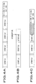
- FIGs. 4A to 4C show schematic views of extents which are composed of logical sectors to which file data is divisionally recorded.
- FIG.4A shows arrangement of a case in which writing processing is normally performed, indicating extents, above-described File Entry ICB, File Identifier Descriptor, VAT, VAT ICB, while FIG.4B shows arrangement of a case in which writing processing after an extent Ex3 is interrupted due to accidental factors during data writing.
- FIG.4C shows the state in which file information such as the File Entry ICB, File Identifier Descriptor, VAT, VAT ICB is restored from the state in which writing processing is interrupted.
- data of large file size is divisionally recorded to extents composed of a plurality of logical sectors, and restoration file information is recorded for each extent.
- the restoration file information is recorded to the head of each extent.
- restoration file information is recorded with restoration file information of previous extent included therein.
- restoration file information to be recorded to an extent includes an address and size of previous extent which has been already recorded.
- a file is divisionally recorded to four extents of extent Ex1, extent Ex2, extent Ex3, and extent Ex4.
- extent Ex1 when the extent Ex1 is written to a recording medium, a head address and file size of the extent Ex1 is recorded to a recording medium as restoration file information together with data to be recorded.
- the head address and file size of the extent Ex1 and a head address and file size of the extent Ex2 are recorded to a recording medium as restoration file information together with data to be recorded.
- the head address and file size of the extent Ex1 and extent Ex2, and those of extent Ex3 are recorded to a recording medium as restoration file information together with data to be recorded.
- restoration file information recorded in the extent Ex2 together with data is read out, and file information such as the head address and file size is written following the interrupted extent based on file information recorded in the read out restoration file information.
- restoration file information there are enumerated a file name of an extent to which restoration file information is written, directory information of a file, File Entry ICB, VAT. Furthermore, other information can be used as restoration file information as long as the information shows characteristics of data file.
- the restoration method is extremely effective in writing image data of large data size such as, especially, a moving picture file or a non-compressed still picture image.
- the present invention can be adapted not only to the WORM type recording medium but also to the rewritable type recording medium, and the recording medium is not limited to a CD-R, CD-RW, etc., and an optical disc such as a CD-R/RW (Compact Disc-Recordable/Rewritable), a DVD-RW (Digital Versatile Disc-Rewritable), a DVD-RAM, etc., and a magneto optical disc such as an MO (Magneto Optical Disc), an MD (Mini Disc) can be used.
- CD-R/RW Compact Disc-Recordable/Rewritable
- DVD-RW Digital Versatile Disc-Rewritable
- DVD-RAM Digital Versatile Disc-Rewritable
- a magneto optical disc such as an MO (Magneto Optical Disc), an MD (Mini Disc)
- an apparatus for recording and reproducing data which manages files and records and/or reproduces data based on a virtual allocation table showing correspondence between actual addresses indicative of recording positions of the files on a recording medium and virtual addresses indicative of virtual recording positions of the files, the files having a sequence of data stored therein
- the apparatus including: record and reproduction means for recording and/or reproducing data to and/or from the recording medium; and record control means for controlling the processing of recording file information concerning a file including a sequence of data to a predetermined area of the recording medium as restoration file information when the record and reproduction means records the sequence of data; wherein, when interruption of data recording processing is detected, the record control means retrieves and reads out restoration file information, and restores a file whose recording processing is interrupted based on the restoration file information.
- file information concerning a file including a sequence of data is recorded to a predetermined area of the recording medium as restoration file information, even though there is raised failure in writing data, data before the interruption can be made readable.
- a method for recording and reproducing data which manages files and records and/or reproduces data based on a virtual allocation table showing correspondence between actual addresses indicative of recording positions of the files on a recording medium and virtual addresses indicative of virtual recording positions of the files, the files having a sequence of data stored therein, the method including: data record and restoration file information record step of recording a sequence of data, and recording file information concerning a file including the sequence of data to a predetermined area of the recording medium as restoration file information; restoration file information read out step of retrieving and reading out restoration file information when data recording processing is interrupted at the data record step; and file restoration step of restoring a file whose recording processing is interrupted based on the restoration file information.
- file information concerning a file including a sequence of data is recorded to a predetermined area of the recording medium as restoration file information, even though there is raised failure in writing data, data before the interruption can be made readable by reading out the restoration file information.
- a digital camera including: image capturing means for capturing an object; image processing means for processing captured image data; record and reproduction means for recording and/or reproducing data to and/or from a recording medium; and record control means for managing files having a sequence of data stored therein based on a virtual allocation table showing correspondence between actual addresses indicative of recording positions of the files on the recording medium and virtual addresses indicative of virtual recording positions of the files, and controlling the processing of recording file information concerning a file including a sequence of data to a predetermined area of the recording medium as restoration file information when the record and reproduction means records the sequence of data; wherein, when interruption of data recording processing is detected, the record control means retrieves and reads out restoration file information, and restores a file whose recording processing is interrupted based on the restoration file information.
- file information concerning a file including a sequence of data is recorded to a predetermined area of the recording medium as restoration file information, even though there is raised failure in writing data, data before the interruption can be made readable.
Landscapes
- Engineering & Computer Science (AREA)
- Signal Processing (AREA)
- Multimedia (AREA)
- Signal Processing For Digital Recording And Reproducing (AREA)
- Management Or Editing Of Information On Record Carriers (AREA)
- Information Retrieval, Db Structures And Fs Structures Therefor (AREA)
- Television Signal Processing For Recording (AREA)
- Studio Devices (AREA)
Applications Claiming Priority (3)
| Application Number | Priority Date | Filing Date | Title |
|---|---|---|---|
| JP2001367860A JP3722057B2 (ja) | 2001-11-30 | 2001-11-30 | データ記録再生装置及びデータ記録再生方法、並びにデジタルカメラ |
| JP2001367860 | 2001-11-30 | ||
| PCT/JP2002/011735 WO2003049111A1 (fr) | 2001-11-30 | 2002-11-11 | Dispositif et procede d'enregistrement/lecture de donnees |
Publications (2)
| Publication Number | Publication Date |
|---|---|
| EP1450367A1 true EP1450367A1 (fr) | 2004-08-25 |
| EP1450367A4 EP1450367A4 (fr) | 2009-01-07 |
Family
ID=19177546
Family Applications (1)
| Application Number | Title | Priority Date | Filing Date |
|---|---|---|---|
| EP02788605A Withdrawn EP1450367A4 (fr) | 2001-11-30 | 2002-11-11 | Dispositif et procede d'enregistrement/lecture de donnees |
Country Status (6)
| Country | Link |
|---|---|
| US (1) | US7236689B2 (fr) |
| EP (1) | EP1450367A4 (fr) |
| JP (1) | JP3722057B2 (fr) |
| KR (1) | KR20040064607A (fr) |
| CN (1) | CN100382195C (fr) |
| WO (1) | WO2003049111A1 (fr) |
Cited By (2)
| Publication number | Priority date | Publication date | Assignee | Title |
|---|---|---|---|---|
| US7380134B2 (en) * | 2002-03-20 | 2008-05-27 | Kabushiki Kaisha Toshiba | Information recording/reproducing apparatus and method of executing encryption processing |
| EP4113518A1 (fr) * | 2021-06-29 | 2023-01-04 | Canon Kabushiki Kaisha | Appareil d'édition, son procédé de commande, système d'édition, programme informatique et support d'informations |
Families Citing this family (15)
| Publication number | Priority date | Publication date | Assignee | Title |
|---|---|---|---|---|
| JP2000135820A (ja) * | 1997-12-11 | 2000-05-16 | Canon Inc | 印刷装置及び印刷システム及び印刷制御方法及び印刷装置を制御する印刷制御プログラムを格納した記憶媒体及び印刷装置を制御する印刷制御プログラムを送出する送出装置 |
| JP4140516B2 (ja) | 2003-12-09 | 2008-08-27 | ソニー株式会社 | 記録制御装置および方法、記録媒体、並びにプログラム |
| KR100612221B1 (ko) * | 2004-07-07 | 2006-08-16 | 삼성전자주식회사 | 데이터 복원 기능을 갖는 영상기록재생장치 및 그 방법 |
| JP4085391B2 (ja) * | 2004-08-24 | 2008-05-14 | ソニー株式会社 | 再生装置および再生方法、並びにプログラム |
| KR20060063601A (ko) * | 2004-12-03 | 2006-06-12 | 엘지전자 주식회사 | 로컬 스토리지에 데이터를 다운로드/업데이트 하는 방법 및장치 |
| BRPI0517651A (pt) * | 2004-11-08 | 2008-10-14 | Lg Electronics Inc | método e aparelho para reproduzir dados de meio de gravação, método para atualizar dados de armazenagem local, método para formar pacote virtual |
| JP4806183B2 (ja) | 2004-12-24 | 2011-11-02 | 富士通セミコンダクター株式会社 | ファイル情報の書き込み処理方法およびプログラム |
| JP4498159B2 (ja) * | 2005-02-03 | 2010-07-07 | キヤノン株式会社 | 撮像装置およびその制御方法 |
| EP2490127A1 (fr) * | 2005-03-18 | 2012-08-22 | Sony Corporation | Dispositif de traitement d'informations, procédé de traitement d'informations et programme informatique |
| KR100675852B1 (ko) * | 2005-04-12 | 2007-02-02 | 삼성전자주식회사 | 타이틀 정보 추출에 의한 기록 리스트의 복원이 가능한영상기록장치 및 기록 리스트 복원방법 |
| JP2007122221A (ja) * | 2005-10-26 | 2007-05-17 | Sony Corp | 情報処理装置、および情報処理方法、並びにコンピュータ・プログラム |
| JP5094655B2 (ja) * | 2008-09-12 | 2012-12-12 | キヤノン株式会社 | 撮像装置 |
| JP2011109443A (ja) * | 2009-11-18 | 2011-06-02 | Panasonic Corp | 撮像装置 |
| CN101909189B (zh) * | 2010-07-22 | 2013-01-09 | 杭州海康威视数字技术股份有限公司 | 文件恢复方法、系统及dvr |
| CN102176734B (zh) * | 2010-12-01 | 2013-11-06 | 北京佳讯飞鸿电气股份有限公司 | 一种人工台断电恢复的方法 |
Family Cites Families (26)
| Publication number | Priority date | Publication date | Assignee | Title |
|---|---|---|---|---|
| US4498146A (en) * | 1982-07-30 | 1985-02-05 | At&T Bell Laboratories | Management of defects in storage media |
| US4852100A (en) * | 1986-10-17 | 1989-07-25 | Amdahl Corporation | Error detection and correction scheme for main storage unit |
| US5241672A (en) * | 1991-04-01 | 1993-08-31 | Xerox Corporation | System using the storage level of file updates in nonvolatile memory to trigger saving of RAM to disk and using the file updates to reboot after crash |
| US5274646A (en) * | 1991-04-17 | 1993-12-28 | International Business Machines Corporation | Excessive error correction control |
| US5819020A (en) * | 1995-10-16 | 1998-10-06 | Network Specialists, Inc. | Real time backup system |
| CN1296931C (zh) * | 1996-09-30 | 2007-01-24 | 松下电器产业株式会社 | 一种在盘上记录av数据的记录方法和信息处理系统 |
| JPH10177769A (ja) | 1996-12-13 | 1998-06-30 | Sony Corp | ディスク状記録媒体、ディスクドライブ装置 |
| US6158025A (en) * | 1997-07-28 | 2000-12-05 | Intergraph Corporation | Apparatus and method for memory error detection |
| JPH11259957A (ja) | 1998-03-10 | 1999-09-24 | Toshiba Corp | 記録媒体と記録再生装置 |
| JP3383580B2 (ja) * | 1998-05-15 | 2003-03-04 | 株式会社東芝 | 情報記憶媒体と情報記録再生装置と方法 |
| US6590607B1 (en) * | 1998-08-19 | 2003-07-08 | Hewlett-Packard Development Company, L.P. | Method and apparatus for storing an uninterrupted digital video stream |
| JP3376296B2 (ja) * | 1998-09-30 | 2003-02-10 | 株式会社東芝 | 情報記憶媒体への情報記録方法及び情報記憶媒体及び情報記録装置及び情報再生方法 |
| US6205558B1 (en) * | 1998-10-07 | 2001-03-20 | Symantec Corporation | Recovery of file systems after modification failure |
| FR2784475B1 (fr) * | 1998-10-12 | 2000-12-29 | Centre Nat Etd Spatiales | Procede de traitement d'un systeme electronique soumis a des contraintes d'erreurs transitoires |
| JP3781912B2 (ja) * | 1999-01-19 | 2006-06-07 | 株式会社リコー | 画像記録再生装置 |
| JP2001167558A (ja) | 1999-12-09 | 2001-06-22 | Canon Inc | 記録再生装置及び記録再生方法 |
| JP4169890B2 (ja) * | 1999-11-12 | 2008-10-22 | 松下電器産業株式会社 | 記録装置及びプログラム記録媒体 |
| TW514884B (en) * | 1999-12-03 | 2002-12-21 | Koninkl Philips Electronics Nv | Allocating real time data on a disc like recording medium |
| US6591363B1 (en) | 1999-12-15 | 2003-07-08 | Roxio, Inc. | System for writing incremental packet data to create bootable optical medium by writing boot catalog and boot image onto second track before writing volume descriptors onto first track |
| EP1113666A1 (fr) * | 1999-12-30 | 2001-07-04 | Nokia Corporation | Appareil pour le traitement de données |
| JP3838031B2 (ja) * | 2000-01-11 | 2006-10-25 | 株式会社日立製作所 | 情報記録再生装置および情報記録再生方法 |
| JP2001291366A (ja) | 2000-04-03 | 2001-10-19 | Sony Corp | 記録方法および装置、ならびに、記録媒体 |
| US6701454B1 (en) * | 2000-06-05 | 2004-03-02 | Microsoft Corporation | Method and system for recovering information during a program failure |
| US6701451B1 (en) * | 2000-08-11 | 2004-03-02 | Emc Corporation | Selective correction of data errors |
| JP2002312940A (ja) * | 2001-04-11 | 2002-10-25 | Matsushita Electric Ind Co Ltd | ディスク記録方法、ディスク記録装置、及び記録再生装置 |
| JP3674531B2 (ja) * | 2001-04-12 | 2005-07-20 | 株式会社日立製作所 | ファイル管理方法、ファイル管理装置、プログラム |
-
2001
- 2001-11-30 JP JP2001367860A patent/JP3722057B2/ja not_active Expired - Lifetime
-
2002
- 2002-11-11 EP EP02788605A patent/EP1450367A4/fr not_active Withdrawn
- 2002-11-11 US US10/470,424 patent/US7236689B2/en not_active Expired - Fee Related
- 2002-11-11 CN CNB028043200A patent/CN100382195C/zh not_active Expired - Fee Related
- 2002-11-11 KR KR10-2003-7009997A patent/KR20040064607A/ko not_active Ceased
- 2002-11-11 WO PCT/JP2002/011735 patent/WO2003049111A1/fr not_active Ceased
Cited By (3)
| Publication number | Priority date | Publication date | Assignee | Title |
|---|---|---|---|---|
| US7380134B2 (en) * | 2002-03-20 | 2008-05-27 | Kabushiki Kaisha Toshiba | Information recording/reproducing apparatus and method of executing encryption processing |
| EP4113518A1 (fr) * | 2021-06-29 | 2023-01-04 | Canon Kabushiki Kaisha | Appareil d'édition, son procédé de commande, système d'édition, programme informatique et support d'informations |
| US11990155B2 (en) | 2021-06-29 | 2024-05-21 | Canon Kabushiki Kaisha | Editing apparatus, control method for the same, editing system, and storage medium |
Also Published As
| Publication number | Publication date |
|---|---|
| US7236689B2 (en) | 2007-06-26 |
| EP1450367A4 (fr) | 2009-01-07 |
| KR20040064607A (ko) | 2004-07-19 |
| JP2003169293A (ja) | 2003-06-13 |
| CN1515008A (zh) | 2004-07-21 |
| WO2003049111A1 (fr) | 2003-06-12 |
| JP3722057B2 (ja) | 2005-11-30 |
| CN100382195C (zh) | 2008-04-16 |
| US20040197089A1 (en) | 2004-10-07 |
Similar Documents
| Publication | Publication Date | Title |
|---|---|---|
| US7236689B2 (en) | Data recording/reproducing apparatus and data recording/reproducing method | |
| US8301011B2 (en) | Optical recording apparatus, optical recording method, and digital still camera | |
| JP3580711B2 (ja) | 情報記録再生装置 | |
| JP3997690B2 (ja) | 光記録装置、光記録媒体残量表示方法、撮像装置及び撮像装置の光記録媒体表示方法 | |
| KR20000063067A (ko) | 기록 매체상에 데이터를 기록하고 기록 매체로부터데이터를 재생하여 기록 매체상에 기록된 영역 및 기록가능한 영역 간의 경계를 검출하기 위한 구동 장치 및 방법 | |
| TWI344138B (fr) | ||
| CN101331549B (zh) | 数据记录装置和数据记录方法 | |
| CN1331124C (zh) | 光记录方法和光记录设备 | |
| JP2007509450A (ja) | 情報を記録する装置及び方法 | |
| JP4092907B2 (ja) | データ再生装置及びデータ再生方法、並びにデジタルカメラ | |
| EP1667153A1 (fr) | Enregistreur, procede d'enregistrement, et support d'enregistrement porteur de logiciel | |
| WO2002073614A1 (fr) | Procede d'enregistrement de donnees et appareil d'enregistrement | |
| JP4389397B2 (ja) | データ記録方法及び装置 | |
| JP4281219B2 (ja) | デジタルスチルカメラ、記録再生方法及び記録再生装置 | |
| JP4461635B2 (ja) | 記録媒体認識方法及び装置 | |
| US7693024B2 (en) | Recording/reproducing method and disc | |
| JP2001351335A (ja) | 光記録媒体 | |
| JP2001351336A (ja) | データ再生方法及び装置、並びにデータ記録方法及び装置 | |
| US20070276605A1 (en) | Device and Method for Recording Information | |
| JP2001351240A (ja) | 光記録装置、光記録方法、及びデジタルスチルカメラ | |
| JP2001351241A (ja) | 光記録装置、光記録方法、及び光記録媒体、並びにデジタルスチルカメラ | |
| JP2002015430A (ja) | 追記型記録媒体記録方法及び記録装置 |
Legal Events
| Date | Code | Title | Description |
|---|---|---|---|
| PUAI | Public reference made under article 153(3) epc to a published international application that has entered the european phase |
Free format text: ORIGINAL CODE: 0009012 |
|
| 17P | Request for examination filed |
Effective date: 20030710 |
|
| AK | Designated contracting states |
Kind code of ref document: A1 Designated state(s): AT BE BG CH CY CZ DE DK EE ES FI FR GB GR IE IT LI LU MC NL PT SE SK TR |
|
| AX | Request for extension of the european patent |
Extension state: AL LT LV MK RO SI |
|
| A4 | Supplementary search report drawn up and despatched |
Effective date: 20081204 |
|
| 17Q | First examination report despatched |
Effective date: 20090414 |
|
| STAA | Information on the status of an ep patent application or granted ep patent |
Free format text: STATUS: THE APPLICATION IS DEEMED TO BE WITHDRAWN |
|
| 18D | Application deemed to be withdrawn |
Effective date: 20120601 |