EP1450385A2 - Tastatur für ein tragbares drahtloses Endgerät und Herstellungsverfahren dazu - Google Patents
Tastatur für ein tragbares drahtloses Endgerät und Herstellungsverfahren dazu Download PDFInfo
- Publication number
- EP1450385A2 EP1450385A2 EP03025728A EP03025728A EP1450385A2 EP 1450385 A2 EP1450385 A2 EP 1450385A2 EP 03025728 A EP03025728 A EP 03025728A EP 03025728 A EP03025728 A EP 03025728A EP 1450385 A2 EP1450385 A2 EP 1450385A2
- Authority
- EP
- European Patent Office
- Prior art keywords
- keys
- keypad
- sheet
- holes
- key
- Prior art date
- Legal status (The legal status is an assumption and is not a legal conclusion. Google has not performed a legal analysis and makes no representation as to the accuracy of the status listed.)
- Granted
Links
- 238000000034 method Methods 0.000 title claims description 22
- 238000004519 manufacturing process Methods 0.000 title description 3
- 239000012790 adhesive layer Substances 0.000 claims abstract description 15
- 239000000463 material Substances 0.000 claims description 17
- 238000001746 injection moulding Methods 0.000 claims description 9
- 239000004033 plastic Substances 0.000 claims description 6
- 239000002210 silicon-based material Substances 0.000 claims description 4
- 230000008878 coupling Effects 0.000 claims 1
- 238000010168 coupling process Methods 0.000 claims 1
- 238000005859 coupling reaction Methods 0.000 claims 1
- 238000005507 spraying Methods 0.000 claims 1
- XUIMIQQOPSSXEZ-UHFFFAOYSA-N Silicon Chemical compound [Si] XUIMIQQOPSSXEZ-UHFFFAOYSA-N 0.000 abstract description 5
- 238000005034 decoration Methods 0.000 abstract description 5
- 229910052710 silicon Inorganic materials 0.000 abstract description 5
- 239000010703 silicon Substances 0.000 abstract description 5
- 238000013461 design Methods 0.000 abstract description 3
- 239000000853 adhesive Substances 0.000 description 6
- 230000001070 adhesive effect Effects 0.000 description 5
- 230000005540 biological transmission Effects 0.000 description 4
- 238000002347 injection Methods 0.000 description 4
- 239000007924 injection Substances 0.000 description 4
- 239000010410 layer Substances 0.000 description 3
- 239000011347 resin Substances 0.000 description 3
- 229920005989 resin Polymers 0.000 description 3
- 239000011248 coating agent Substances 0.000 description 2
- 238000000576 coating method Methods 0.000 description 2
- 238000004891 communication Methods 0.000 description 2
- 239000010408 film Substances 0.000 description 2
- 238000003825 pressing Methods 0.000 description 2
- 238000004080 punching Methods 0.000 description 2
- 230000003796 beauty Effects 0.000 description 1
- 230000008859 change Effects 0.000 description 1
- 239000002131 composite material Substances 0.000 description 1
- 238000012986 modification Methods 0.000 description 1
- 230000004048 modification Effects 0.000 description 1
- 238000000465 moulding Methods 0.000 description 1
- 238000010422 painting Methods 0.000 description 1
- 238000012805 post-processing Methods 0.000 description 1
- 238000012545 processing Methods 0.000 description 1
- 230000004044 response Effects 0.000 description 1
- 239000007779 soft material Substances 0.000 description 1
- 239000007921 spray Substances 0.000 description 1
- 238000007592 spray painting technique Methods 0.000 description 1
- 239000010409 thin film Substances 0.000 description 1
- 230000000007 visual effect Effects 0.000 description 1
Images


Classifications
-
- H—ELECTRICITY
- H01—ELECTRIC ELEMENTS
- H01H—ELECTRIC SWITCHES; RELAYS; SELECTORS; EMERGENCY PROTECTIVE DEVICES
- H01H13/00—Switches having rectilinearly-movable operating part or parts adapted for pushing or pulling in one direction only, e.g. push-button switch
- H01H13/70—Switches having rectilinearly-movable operating part or parts adapted for pushing or pulling in one direction only, e.g. push-button switch having a plurality of operating members associated with different sets of contacts, e.g. keyboard
- H01H13/702—Switches having rectilinearly-movable operating part or parts adapted for pushing or pulling in one direction only, e.g. push-button switch having a plurality of operating members associated with different sets of contacts, e.g. keyboard with contacts carried by or formed from layers in a multilayer structure, e.g. membrane switches
-
- H—ELECTRICITY
- H04—ELECTRIC COMMUNICATION TECHNIQUE
- H04M—TELEPHONIC COMMUNICATION
- H04M1/00—Substation equipment, e.g. for use by subscribers
- H04M1/02—Constructional features of telephone sets
- H04M1/23—Construction or mounting of dials or of equivalent devices; Means for facilitating the use thereof
-
- H—ELECTRICITY
- H01—ELECTRIC ELEMENTS
- H01H—ELECTRIC SWITCHES; RELAYS; SELECTORS; EMERGENCY PROTECTIVE DEVICES
- H01H2221/00—Actuators
- H01H2221/002—Actuators integral with membrane
-
- H—ELECTRICITY
- H01—ELECTRIC ELEMENTS
- H01H—ELECTRIC SWITCHES; RELAYS; SELECTORS; EMERGENCY PROTECTIVE DEVICES
- H01H2221/00—Actuators
- H01H2221/002—Actuators integral with membrane
- H01H2221/006—Adhesive
-
- H—ELECTRICITY
- H01—ELECTRIC ELEMENTS
- H01H—ELECTRIC SWITCHES; RELAYS; SELECTORS; EMERGENCY PROTECTIVE DEVICES
- H01H2221/00—Actuators
- H01H2221/05—Force concentrator; Actuating dimple
-
- H—ELECTRICITY
- H01—ELECTRIC ELEMENTS
- H01H—ELECTRIC SWITCHES; RELAYS; SELECTORS; EMERGENCY PROTECTIVE DEVICES
- H01H2229/00—Manufacturing
- H01H2229/044—Injection moulding
- H01H2229/048—Insertion moulding
-
- H—ELECTRICITY
- H01—ELECTRIC ELEMENTS
- H01H—ELECTRIC SWITCHES; RELAYS; SELECTORS; EMERGENCY PROTECTIVE DEVICES
- H01H2231/00—Applications
- H01H2231/022—Telephone handset
-
- H—ELECTRICITY
- H04—ELECTRIC COMMUNICATION TECHNIQUE
- H04M—TELEPHONIC COMMUNICATION
- H04M1/00—Substation equipment, e.g. for use by subscribers
- H04M1/02—Constructional features of telephone sets
- H04M1/0202—Portable telephone sets, e.g. cordless phones, mobile phones or bar type handsets
- H04M1/0279—Improving the user comfort or ergonomics
- H04M1/0283—Improving the user comfort or ergonomics for providing a decorative aspect, e.g. customization of casings, exchangeable faceplate
Definitions
- the present invention generally relates to input devices, and more particularly to an input device for inputting information into an electronic system including but not limited to a portable wireless terminal.
- the present invention is also a method for a keypad of this type.
- Communication terminals generally include telephones commonly used in the home or office and portable wireless terminals.
- Portable wireless terminals have developed more functions as wireless communication techniques have evolved. These functions include voice transmission/reception, letter message transmission, data transmission, and image transmission/reception.
- a keypad used as a switching device for generating input signals and setting various functions is used not only in general telephones but also in portable wireless terminals. Keypads of this type have keys on which numbers and letters are printed, and the keys are assembled in a front housing of the terminal in an operative state. The keypad is used to perform various functions, and is externally exposed thereby making its design, preference pattern, visual effect, and endurance very important.
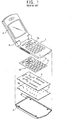
- Figure 1 shows disassembled view of a portable wireless terminal.
- This terminal includes a folder 2 coupled to one side of a front case 1 by a hinge 3.
- a rear case 4 is also coupled to the front case.
- a printed circuit board 5 has contact points 5a arranged at an inner space formed between the front and rear cases.
- a dome switch assembly 6 is located adjacent the printed circuit board and a keypad made of a hard material is arranged on the dome switch assembly.
- the keypad is formed of a thin-film sheet 11 and keys 12 are formed on an upper surface of the sheet. The keys are inserted into respective holes 1a in the front case in such a manner that a part of each key is exposed to an outer portion of the terminal through the holes 1a.
- FIG 2 shows.an isolated view of a related-art keypad which may be inserted into the portable wireless terminal shown in Figure 1, and Figure 3 is a sectional view taken along line A-A of Figure 2.
- a dome switch 6 having an elastic force and a restoration force is mounted on the printed board 5
- keypad 10 having a key 12 formed on one part of sheet 11 is located adjacent the dome switch.
- a soft silicon material 13 is molded into the key.
- each key of the keypad is made of a hard material, which makes its forming operation difficult and makes it difficult to change the key into various designs. That is, since a film of hard material is used to form each key, shapes of the keys are limited. For example, an edge part of each key is smashed which gives the key an ambiguous appearance. Also, since it is difficult to form a decoration line for beauty at the key surface, the appearance of the key is not beautiful.
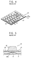
- FIG 4 shows another related-art keypad for a portable wireless terminal
- Figure 5 is a sectional view taken along line B-B of Figure 4.
- dome switch 6 is mounted on a printed circuit board 5 and a supporting member 23 of silicon material and having a protrusion 23a is located on the dome switch.
- a keypad 20 is installed on an upper surface of the supporting member, and a plurality of keys 22 of plastic material are attached to predetermined positions on an upper surface of a pad sheet 21 of the keypad using an adhesive (not shown).
- the aforementioned related-art keypad also has a number of drawbacks. For example, when appearance is processed by spray painting and ultraviolet coating, the painting and coating are applied to an adhesion part of the keys. As a result, the keys do not adhere to the keypad completely but are shaken, or an adhesion position of the keys becomes deteriorated or distorted. Also, since heights of the keys are different from one another based on the amount of adhesive applied to fix each key to the pad sheet, each key has a different feeling or touch which thereby degrades reliability of the product. Also, since the keys are not in precise alignment with the key holes in the front case, quality of appearance is deteriorated and the user has a degraded pressing feeling for the keys.
- An object of the invention is to solve at least one the above problems and/or disadvantages of the related-art keypads discussed above.
- Another object of the present invention is to provide a keypad of an electronic device such as but not limited to a portable wireless terminal, in which keys are easily and firmly fixed in precise positions of a keypad and relative to key holes in a front housing of the terminal.
- Another object of the present invention is to provide a keypad of an electronic device, such as but not limited to a portable wireless terminal, which has keys of uniform height in order to improve key tactility during use.
- Another object of the present invention is to provide a method of making any one or more of aforementioned keypads.
- the present invention provides a keypad of a portable wireless terminal comprising: a sheet in which a plurality of holes are perforated; a plurality of keys inserted into respective holes of the sheet; and a silicon adhesive layer adhered to a lower surface of the sheet s to fix the keys to the sheet and having a protrusion at a lower surface thereof in order to touch a dome switch.
- a stopping portion, protruding outwardly by being inserted into the sheet holes, is formed at a lower circumferential surface of the keys in order to be inserted into the holes of the sheet.
- the present invention is also a method for fabricating a keypad of a portable wireless terminal comprising the steps of: punching-processing a plurality of holes at a file material of a sheet; inserting the keys into respective holes of the sheet; and forming a silicon adhesive layer at a lower surface of the sheet and thus fixing the keys to the sheet.
- the keys are inserted into the holes of the sheet by an insert injection molding method.
- Figure 1 is a disassembled view showing parts of a portable wireless terminal
- Figure 2 is a view showing a related-art keypad which may be adapted for use in the portable wireless terminal of Figure 1;
- Figure 3 is a sectional view taken along line A-A of Figure 2;
- Figure 4 is a view showing another related-art keypad which may be adapted for use in the portable wireless terminal of Figure 1;
- Figure 5 is a sectional view taken along line B-B of Figure 4.
- Figure 6(A) is a perspective view showing a portable wireless terminal according to a preferred embodiment of the present invention
- Figure 6(B) is an exploded sectional view showing one portion of the keypad in the terminal of Figure 6(A);
- Figure 7 is a longitudinal section view showing a keypad of the portable wireless terminal according to the present invention.
- Figure 8 is a view for explaining a pin-point gate method which may be used to form the keys of the keypad of the present invention.
- Figure 9 is a flow chart showing steps included in a method for making a keypad of a portable wireless terminal according to an embodiment of the present invention.
- Figure 6(A) is a view showing a portable wireless terminal according to a preferred embodiment of the present invention
- Figure 6(B) is an exploded sectional view of a portion of a keypad included in the terminal of Figure 6(A)
- Figure 7 is a cross-sectional view of one key in the keypad shown in Figures 6(A) and 6(B).
- the terminal includes a folder 111 coupled to one side of a front case 110 by a hinge 111a, which allows the folder to be folded.
- a rear case 120 is coupled to the front case.
- a printed circuit board 130 having a contact point 130a is located at an inner space formed between the front case and the rear case.
- a plurality of dome switches 140 are respectively arranged on the printed circuit board 130 and a keypad 150 includes keys 152 in alignment with respective ones of the dome switches.
- a plurality of holes 151a are formed at an upper surface of a sheet 151 of the keypad.
- Keys 152 preferably made of a plastic material, are inserted and assembled into respective ones of the holes 151a using, for example, an insert injection-molding process.
- a stopping portion 152a is preferably formed at a lower portion of the keys 152. This stopping portion may be integrally formed with each key as a result of the injection-molding process.
- a recess 180 may be formed in the key preferably along its outer surface. If desired, the recess may traverse a circumferential path around this. As shown in Figure 7, inner surfaces 186 and 187 above and below the recess contact portions of the sheet near each hole. This contact and more specifically the stopping portion 152a formed at least in part by surface 187 operates to hold the key firmly within the hole.
- a adhesion layer 153 preferably made of silicon, is adhered to a lower surface of the sheet 151 and preferably to a periphery of stopping portion 152a.
- the adhesive layer thus, provides an additional force for fixing the keys 152 into the holes of the sheet.
- a protrusion 153a is formed at a lower surface of the adhesion layer in order to touch or at least be in close proximity to the dome switches 140.
- the protrusion 153a of the adhesion layer 153 presses against the dome switches 140.
- the dome switch deflects in response to this force, thereby touching a contact point 130a on the printed circuit board to initiate a desired operation.
- each key 152 of the keypad is firmly held within a respective hole 151a of the sheet by stopping portion 152a, which is preferably but not necessarily formed at a lower surface of the keys.
- the optional adhesive layer is adhered to a lower portion of the key and the sheet. In this position, the adhesive layer provides an additional force for fastening the keys to the holes in the sheet.
- the stopping portion and/or the adhesive layer the keys in the keypad of the present invention are assured of being firmly fixed on the sheet and precisely located relative to the key holes in the terminal housing.
- Figure 8 is a view explaining a pin-point gate method which is preferably used to form the keypad of the present invention.
- the sheet is turned over between a lower metallic pattern M1 and an upper metallic pattern M2.
- An adhesive material (e.g., silicon) 153 is then injected into the lower portion of the keys through an injection opening H of the upper metallic pattern M2 in accordance with the pin-point gate method, thereby simultaneously and very rapidly assembling the keys onto the sheet.
- FIG. 9 is a flow chart showing steps included in a method of making a keypad of a portable wireless terminal according to a preferred embodiment of the present invention.
- This method includes forming a plurality of holes in a sheet of preferably hard film material using, for example, a punching machine. The holes will accommodate one or more keys of the keypad, S210.
- keys of preferably a plastic or rubber material are inserted into the respective holes of the sheet. This may be accomplished by an insert injection molding method, S220.
- the sheet is then turned over to assume a state where the keys are inserted into respective holes between a lower metallic pattern and an upper metallic pattern.
- Adhesive material is then injected into the lower portion of each key using a pin-point gate method, which preferably involves injecting the adhesive through more than two injection openings, thereby firmly mounting each key to the sheet.
- the plurality of holes are formed at predetermined positions in the sheet.
- the keys are inserted into the holes of the sheet preferably using an insert injection-molding method, which allows the keys to be molded within the holds of the sheet. At this time, because the material which is injected into the sheet holes overlaps onto both sides of the portion of the sheet forming the holes, the recess and stopping portion previously discussed will be formed.
- composite components may be fabricated by integrating a workpiece in with resin. This is accomplished by putting or inserting the workpiece in the metallic pattern and then injecting the resin.
- the sheet of the present invention corresponds to the work piece.
- the stopping portion of the keys formed by the insert injection molding method is advantageous because it prevents each key from being released from a respective hole of the sheet.
- the keys can be formed of plastic (resin), rubber, or another suitable material to suit the user's taste.
- keys are inserted into and held within holes of a sheet using a key molding metallic pattern.
- all keys of the keypad are formed simultaneously, using the pin-point method which involves injecting injection material through more than two injection openings. Accordingly, it is easy to form a decoration line or a decoration shape at the appearance of the keys when the keys are formed and thus a beautiful keypad can be formed.
- the adhesive layer of soft material is formed at the lower portion of the sheet in order to provide additional force for fixing the keys within the holes of the sheet. This minimizes the impact applied to the dome switches and thus improves pressing tactility.
- the adhesive layer can be formed by bonding according to a general adhesive agent or by a rubber metallic pattern or by another known technique. Also, it is preferable to include a step for spray post-processing the appearance of the keys to thereby enhance tactility of the keys according to the user's taste.
Landscapes
- Engineering & Computer Science (AREA)
- Signal Processing (AREA)
- Push-Button Switches (AREA)
- Telephone Set Structure (AREA)
- Input From Keyboards Or The Like (AREA)
- Manufacture Of Switches (AREA)
Applications Claiming Priority (2)
| Application Number | Priority Date | Filing Date | Title |
|---|---|---|---|
| KR2003010736 | 2003-02-20 | ||
| KR1020030010736A KR100539780B1 (ko) | 2003-02-20 | 2003-02-20 | 휴대용 무선 단말기의 키패드 및 그 제조방법 |
Publications (3)
| Publication Number | Publication Date |
|---|---|
| EP1450385A2 true EP1450385A2 (de) | 2004-08-25 |
| EP1450385A3 EP1450385A3 (de) | 2006-05-10 |
| EP1450385B1 EP1450385B1 (de) | 2013-03-20 |
Family
ID=32733147
Family Applications (1)
| Application Number | Title | Priority Date | Filing Date |
|---|---|---|---|
| EP03025728A Expired - Lifetime EP1450385B1 (de) | 2003-02-20 | 2003-11-10 | Tastatur für ein tragbares drahtloses Endgerät und Herstellungsverfahren dazu |
Country Status (5)
| Country | Link |
|---|---|
| US (1) | US7277274B2 (de) |
| EP (1) | EP1450385B1 (de) |
| JP (1) | JP2004253384A (de) |
| KR (1) | KR100539780B1 (de) |
| CN (1) | CN1523855A (de) |
Cited By (5)
| Publication number | Priority date | Publication date | Assignee | Title |
|---|---|---|---|---|
| EP1748515A1 (de) * | 2005-07-26 | 2007-01-31 | Samsung Electronics Co.,Ltd. | Antenne für eines Mobiltelefons |
| WO2008081243A3 (en) * | 2006-12-21 | 2008-11-20 | Nokia Corp | User input for an electronic device |
| EP2226822A1 (de) | 2009-02-26 | 2010-09-08 | Research In Motion Limited | Schlüsselanordnung für eine tragbare elektronische Vorrichtung mit einer einteiligen Schlüsselkappe |
| US8263887B2 (en) | 2009-02-26 | 2012-09-11 | Research In Motion Limited | Backlit key assembly having a reduced thickness |
| US8723062B2 (en) | 2009-02-26 | 2014-05-13 | Blackberry Limited | Key assembly for a handheld electronic device having a one-piece keycap |
Families Citing this family (12)
| Publication number | Priority date | Publication date | Assignee | Title |
|---|---|---|---|---|
| WO2005088945A1 (en) * | 2004-03-17 | 2005-09-22 | Sensetech Co., Ltd | Metal keypad assembly for mobile phone and manufacturing method of keypad |
| US7715889B2 (en) * | 2004-07-29 | 2010-05-11 | Kyocera Corporation | Portable electronic device |
| KR100652692B1 (ko) * | 2004-11-05 | 2006-12-07 | 엘지전자 주식회사 | 이동통신 단말기 |
| KR100629053B1 (ko) * | 2005-05-19 | 2006-09-26 | 삼성전자주식회사 | 키 패드 어셈블리 |
| KR101126380B1 (ko) * | 2005-05-31 | 2012-03-28 | 삼성전자주식회사 | 휴대 단말기의 키패드 장치 |
| JP4725279B2 (ja) * | 2005-10-13 | 2011-07-13 | 日本電気株式会社 | キースイッチ構造及びそれを用いた携帯端末装置 |
| TWI320900B (en) * | 2006-01-18 | 2010-02-21 | Darfon Electronics Corp | Key operated apparatus having shield and method of making the same |
| TW200930556A (en) * | 2008-01-02 | 2009-07-16 | Ichia Tech Inc | Manufacturing process for keystroke module with non-backlight type faceplate |
| TWM334994U (en) * | 2008-01-02 | 2008-06-21 | Ichia Tech Inc | Key module of non-backlit panel and panel assemblies |
| CN101677038B (zh) * | 2008-09-19 | 2013-06-05 | 深圳富泰宏精密工业有限公司 | 背光键盘 |
| US20120084966A1 (en) * | 2010-10-07 | 2012-04-12 | Microsoft Corporation | Method of making an interactive keyboard |
| TWI801252B (zh) * | 2022-05-30 | 2023-05-01 | 融程電訊股份有限公司 | 具有不同顏色之按鍵的無線電對講機的按鍵結構及其製造方法 |
Citations (1)
| Publication number | Priority date | Publication date | Assignee | Title |
|---|---|---|---|---|
| US5362934A (en) | 1990-10-30 | 1994-11-08 | Teikoku Tsushin Kogyo Co., Ltd. | Push-button switch, keytop, and method of manufacturing the keytop |
Family Cites Families (20)
| Publication number | Priority date | Publication date | Assignee | Title |
|---|---|---|---|---|
| JPS56128523A (en) * | 1980-03-11 | 1981-10-08 | Matsushita Electric Industrial Co Ltd | Method of producing keyboard switch |
| US4775574A (en) * | 1986-04-14 | 1988-10-04 | Shin Etsu Polymer Co., Ltd. | Covering member of keyboard and a base plate therefor |
| US4892981A (en) * | 1988-09-26 | 1990-01-09 | Richard Soloway | Snap-in modular keypad apparatus |
| JP2665712B2 (ja) | 1993-03-16 | 1997-10-22 | 帝国通信工業株式会社 | 押釦スイッチのキートップ板 |
| JPH07312137A (ja) | 1994-05-13 | 1995-11-28 | Fuji Polymertech Kk | クリックタイプのメンブレンスイッチの製造法 |
| JP3103833B2 (ja) | 1994-08-10 | 2000-10-30 | 信越ポリマー株式会社 | 照光式押釦スイッチ装置 |
| JP3516020B2 (ja) | 1994-08-16 | 2004-04-05 | 信越ポリマー株式会社 | 押釦スイッチ用キーシート部材の製造方法 |
| CN1138170A (zh) | 1995-06-14 | 1996-12-18 | 新巨企业股份有限公司 | 键盘按键 |
| JP3151553B2 (ja) * | 1996-11-29 | 2001-04-03 | 帝国通信工業株式会社 | キートップ板及びその製造方法 |
| KR100302462B1 (ko) | 1997-12-29 | 2001-11-30 | 양윤홍 | 다수의버튼을갖는버튼집합체 |
| JP3755787B2 (ja) | 1998-03-09 | 2006-03-15 | ポリマテック株式会社 | 被覆層付きキーパッド |
| JP2000224280A (ja) * | 1999-01-28 | 2000-08-11 | Matsushita Electric Ind Co Ltd | スイッチ装置およびそのスイッチ装置を用いた携帯端末装置 |
| CN2400887Y (zh) | 1999-07-16 | 2000-10-11 | 陈忠义 | 按键橡胶薄膜结构 |
| JP3810237B2 (ja) * | 1999-11-19 | 2006-08-16 | 信越ポリマー株式会社 | 押釦スイッチ用キートップ部材の製造方法 |
| US6576856B2 (en) * | 2000-03-24 | 2003-06-10 | Polymatech Co., Ltd. | Sheet shaped key top |
| JP2001345027A (ja) | 2000-05-31 | 2001-12-14 | Nec Shizuoka Ltd | キースイッチ装置およびその組立方法 |
| JP3630116B2 (ja) * | 2000-08-10 | 2005-03-16 | セイコーエプソン株式会社 | 電気光学ユニットおよび電子機器 |
| KR100337786B1 (ko) * | 2000-08-19 | 2002-05-24 | 윤종용 | 와이드 키패드 및 정전기 방지용 와이드 키패드 결합구조 |
| KR100377638B1 (ko) | 2001-05-18 | 2003-03-26 | 주식회사 유일전자 | 플라스틱 키를 갖는 휴대폰용 키패드 제조방법 |
| TW556947U (en) * | 2002-06-21 | 2003-10-01 | Quanta Comp Inc | Key stroke structure |
-
2003
- 2003-02-20 KR KR1020030010736A patent/KR100539780B1/ko not_active Expired - Fee Related
- 2003-11-10 EP EP03025728A patent/EP1450385B1/de not_active Expired - Lifetime
- 2003-11-18 US US10/714,602 patent/US7277274B2/en not_active Expired - Fee Related
- 2003-12-04 CN CNA2003101207792A patent/CN1523855A/zh active Pending
-
2004
- 2004-02-16 JP JP2004039095A patent/JP2004253384A/ja active Pending
Patent Citations (1)
| Publication number | Priority date | Publication date | Assignee | Title |
|---|---|---|---|---|
| US5362934A (en) | 1990-10-30 | 1994-11-08 | Teikoku Tsushin Kogyo Co., Ltd. | Push-button switch, keytop, and method of manufacturing the keytop |
Cited By (9)
| Publication number | Priority date | Publication date | Assignee | Title |
|---|---|---|---|---|
| EP1748515A1 (de) * | 2005-07-26 | 2007-01-31 | Samsung Electronics Co.,Ltd. | Antenne für eines Mobiltelefons |
| US7388547B2 (en) | 2005-07-26 | 2008-06-17 | Samsung Electronics Co., Ltd. | Antenna for portable terminal |
| CN1905272B (zh) * | 2005-07-26 | 2012-07-11 | 三星电子株式会社 | 用于便携式终端的天线 |
| WO2008081243A3 (en) * | 2006-12-21 | 2008-11-20 | Nokia Corp | User input for an electronic device |
| US7982715B2 (en) | 2006-12-21 | 2011-07-19 | Nokia Corporation | User input for an electronic device |
| EP2226822A1 (de) | 2009-02-26 | 2010-09-08 | Research In Motion Limited | Schlüsselanordnung für eine tragbare elektronische Vorrichtung mit einer einteiligen Schlüsselkappe |
| US8263887B2 (en) | 2009-02-26 | 2012-09-11 | Research In Motion Limited | Backlit key assembly having a reduced thickness |
| US8723062B2 (en) | 2009-02-26 | 2014-05-13 | Blackberry Limited | Key assembly for a handheld electronic device having a one-piece keycap |
| US9208970B2 (en) | 2009-02-26 | 2015-12-08 | Blackberry Limited | Key assembly for a handheld electronic device having a one-piece keycap |
Also Published As
| Publication number | Publication date |
|---|---|
| KR100539780B1 (ko) | 2006-01-10 |
| EP1450385A3 (de) | 2006-05-10 |
| CN1523855A (zh) | 2004-08-25 |
| US20040165364A1 (en) | 2004-08-26 |
| JP2004253384A (ja) | 2004-09-09 |
| EP1450385B1 (de) | 2013-03-20 |
| US7277274B2 (en) | 2007-10-02 |
| KR20040075223A (ko) | 2004-08-27 |
Similar Documents
| Publication | Publication Date | Title |
|---|---|---|
| US7277274B2 (en) | Keypad of portable wireless terminal and fabrication method thereof | |
| KR100342959B1 (ko) | 휴대폰용 키패드와 그 제작방법 | |
| US6809660B2 (en) | Keypad and electronic device | |
| CA2056828C (en) | Keypad and method of manufacture | |
| JPH0897888A (ja) | 複数の区別される電話外観を可能にする携帯用電話 | |
| EP1028445B1 (de) | Tragstruktur für Tastatur | |
| KR100310040B1 (ko) | 휴대폰용 키패드와 그 제작방법 | |
| KR20030006478A (ko) | 정전기 방전 구조를 갖는 키패드와 그 제작방법 | |
| US7228111B2 (en) | Keypad structure | |
| KR200326795Y1 (ko) | 이동통신 단말기의 키입력부 | |
| JP2005190743A (ja) | キーシート一体型筐体パネル | |
| JP3380431B2 (ja) | 電子機器におけるツマミ取付構造 | |
| US20070275751A1 (en) | Faceplate having keys for mobile phone | |
| KR100631662B1 (ko) | 버튼 어셈블리 및 그 버튼 어셈블리를 구비한 휴대 단말기 | |
| KR100647981B1 (ko) | 전화기의 키 패드 러버 성형구조 | |
| KR200194755Y1 (ko) | 플립키 타입 휴대전화기 | |
| KR100418326B1 (ko) | 휴대폰용 키패드 | |
| KR20020028269A (ko) | 휴대용 무선단말기의 일체형 키패드 | |
| KR100732993B1 (ko) | 이동통신단말기용 키패드 조립체 | |
| KR20070091413A (ko) | 2중 박판 키패드 | |
| KR100459772B1 (ko) | 키버튼 어셈블리 | |
| KR200374991Y1 (ko) | 휴대폰용 키-패드의 구조 | |
| JP2001117703A (ja) | キー構造 | |
| KR20060076521A (ko) | 접점푸셔 및 그 접점푸셔를 갖는 휴대폰 키 스위치 | |
| KR20050088651A (ko) | 핸드폰용 키패드 및 이를 제조하는 방법 |
Legal Events
| Date | Code | Title | Description |
|---|---|---|---|
| PUAI | Public reference made under article 153(3) epc to a published international application that has entered the european phase |
Free format text: ORIGINAL CODE: 0009012 |
|
| 17P | Request for examination filed |
Effective date: 20031110 |
|
| AK | Designated contracting states |
Kind code of ref document: A2 Designated state(s): AT BE BG CH CY CZ DE DK EE ES FI FR GB GR HU IE IT LI LU MC NL PT RO SE SI SK TR |
|
| AX | Request for extension of the european patent |
Extension state: AL LT LV MK |
|
| PUAL | Search report despatched |
Free format text: ORIGINAL CODE: 0009013 |
|
| AK | Designated contracting states |
Kind code of ref document: A3 Designated state(s): AT BE BG CH CY CZ DE DK EE ES FI FR GB GR HU IE IT LI LU MC NL PT RO SE SI SK TR |
|
| AX | Request for extension of the european patent |
Extension state: AL LT LV MK |
|
| AKX | Designation fees paid |
Designated state(s): AT BE BG CH CY CZ DE DK EE ES FI FR GB GR HU IE IT LI LU MC NL PT RO SE SI SK TR |
|
| 17Q | First examination report despatched |
Effective date: 20100212 |
|
| RAP1 | Party data changed (applicant data changed or rights of an application transferred) |
Owner name: LG ELECTRONICS INC. |
|
| GRAP | Despatch of communication of intention to grant a patent |
Free format text: ORIGINAL CODE: EPIDOSNIGR1 |
|
| RIC1 | Information provided on ipc code assigned before grant |
Ipc: H04M 1/02 20060101ALI20120919BHEP Ipc: H01H 13/70 20060101AFI20120919BHEP Ipc: H01H 13/702 20060101ALN20120919BHEP Ipc: H04M 1/23 20060101ALN20120919BHEP |
|
| GRAS | Grant fee paid |
Free format text: ORIGINAL CODE: EPIDOSNIGR3 |
|
| GRAA | (expected) grant |
Free format text: ORIGINAL CODE: 0009210 |
|
| AK | Designated contracting states |
Kind code of ref document: B1 Designated state(s): AT BE BG CH CY CZ DE DK EE ES FI FR GB GR HU IE IT LI LU MC NL PT RO SE SI SK TR |
|
| REG | Reference to a national code |
Ref country code: GB Ref legal event code: FG4D |
|
| REG | Reference to a national code |
Ref country code: CH Ref legal event code: EP |
|
| REG | Reference to a national code |
Ref country code: IE Ref legal event code: FG4D |
|
| REG | Reference to a national code |
Ref country code: AT Ref legal event code: REF Ref document number: 602523 Country of ref document: AT Kind code of ref document: T Effective date: 20130415 |
|
| REG | Reference to a national code |
Ref country code: DE Ref legal event code: R096 Ref document number: 60343543 Country of ref document: DE Effective date: 20130516 |
|
| REG | Reference to a national code |
Ref country code: NL Ref legal event code: T3 |
|
| PG25 | Lapsed in a contracting state [announced via postgrant information from national office to epo] |
Ref country code: ES Free format text: LAPSE BECAUSE OF FAILURE TO SUBMIT A TRANSLATION OF THE DESCRIPTION OR TO PAY THE FEE WITHIN THE PRESCRIBED TIME-LIMIT Effective date: 20130701 Ref country code: SE Free format text: LAPSE BECAUSE OF FAILURE TO SUBMIT A TRANSLATION OF THE DESCRIPTION OR TO PAY THE FEE WITHIN THE PRESCRIBED TIME-LIMIT Effective date: 20130320 Ref country code: BG Free format text: LAPSE BECAUSE OF FAILURE TO SUBMIT A TRANSLATION OF THE DESCRIPTION OR TO PAY THE FEE WITHIN THE PRESCRIBED TIME-LIMIT Effective date: 20130620 |
|
| REG | Reference to a national code |
Ref country code: AT Ref legal event code: MK05 Ref document number: 602523 Country of ref document: AT Kind code of ref document: T Effective date: 20130320 |
|
| PG25 | Lapsed in a contracting state [announced via postgrant information from national office to epo] |
Ref country code: GR Free format text: LAPSE BECAUSE OF FAILURE TO SUBMIT A TRANSLATION OF THE DESCRIPTION OR TO PAY THE FEE WITHIN THE PRESCRIBED TIME-LIMIT Effective date: 20130621 Ref country code: SI Free format text: LAPSE BECAUSE OF FAILURE TO SUBMIT A TRANSLATION OF THE DESCRIPTION OR TO PAY THE FEE WITHIN THE PRESCRIBED TIME-LIMIT Effective date: 20130320 Ref country code: FI Free format text: LAPSE BECAUSE OF FAILURE TO SUBMIT A TRANSLATION OF THE DESCRIPTION OR TO PAY THE FEE WITHIN THE PRESCRIBED TIME-LIMIT Effective date: 20130320 |
|
| PG25 | Lapsed in a contracting state [announced via postgrant information from national office to epo] |
Ref country code: BE Free format text: LAPSE BECAUSE OF FAILURE TO SUBMIT A TRANSLATION OF THE DESCRIPTION OR TO PAY THE FEE WITHIN THE PRESCRIBED TIME-LIMIT Effective date: 20130320 |
|
| PG25 | Lapsed in a contracting state [announced via postgrant information from national office to epo] |
Ref country code: EE Free format text: LAPSE BECAUSE OF FAILURE TO SUBMIT A TRANSLATION OF THE DESCRIPTION OR TO PAY THE FEE WITHIN THE PRESCRIBED TIME-LIMIT Effective date: 20130320 Ref country code: AT Free format text: LAPSE BECAUSE OF FAILURE TO SUBMIT A TRANSLATION OF THE DESCRIPTION OR TO PAY THE FEE WITHIN THE PRESCRIBED TIME-LIMIT Effective date: 20130320 Ref country code: RO Free format text: LAPSE BECAUSE OF FAILURE TO SUBMIT A TRANSLATION OF THE DESCRIPTION OR TO PAY THE FEE WITHIN THE PRESCRIBED TIME-LIMIT Effective date: 20130320 Ref country code: SK Free format text: LAPSE BECAUSE OF FAILURE TO SUBMIT A TRANSLATION OF THE DESCRIPTION OR TO PAY THE FEE WITHIN THE PRESCRIBED TIME-LIMIT Effective date: 20130320 Ref country code: CZ Free format text: LAPSE BECAUSE OF FAILURE TO SUBMIT A TRANSLATION OF THE DESCRIPTION OR TO PAY THE FEE WITHIN THE PRESCRIBED TIME-LIMIT Effective date: 20130320 Ref country code: PT Free format text: LAPSE BECAUSE OF FAILURE TO SUBMIT A TRANSLATION OF THE DESCRIPTION OR TO PAY THE FEE WITHIN THE PRESCRIBED TIME-LIMIT Effective date: 20130722 |
|
| PG25 | Lapsed in a contracting state [announced via postgrant information from national office to epo] |
Ref country code: CY Free format text: LAPSE BECAUSE OF FAILURE TO SUBMIT A TRANSLATION OF THE DESCRIPTION OR TO PAY THE FEE WITHIN THE PRESCRIBED TIME-LIMIT Effective date: 20130320 |
|
| PLBE | No opposition filed within time limit |
Free format text: ORIGINAL CODE: 0009261 |
|
| STAA | Information on the status of an ep patent application or granted ep patent |
Free format text: STATUS: NO OPPOSITION FILED WITHIN TIME LIMIT |
|
| PG25 | Lapsed in a contracting state [announced via postgrant information from national office to epo] |
Ref country code: DK Free format text: LAPSE BECAUSE OF FAILURE TO SUBMIT A TRANSLATION OF THE DESCRIPTION OR TO PAY THE FEE WITHIN THE PRESCRIBED TIME-LIMIT Effective date: 20130320 |
|
| 26N | No opposition filed |
Effective date: 20140102 |
|
| PG25 | Lapsed in a contracting state [announced via postgrant information from national office to epo] |
Ref country code: IT Free format text: LAPSE BECAUSE OF FAILURE TO SUBMIT A TRANSLATION OF THE DESCRIPTION OR TO PAY THE FEE WITHIN THE PRESCRIBED TIME-LIMIT Effective date: 20130320 |
|
| REG | Reference to a national code |
Ref country code: DE Ref legal event code: R097 Ref document number: 60343543 Country of ref document: DE Effective date: 20140102 |
|
| REG | Reference to a national code |
Ref country code: CH Ref legal event code: PL |
|
| PG25 | Lapsed in a contracting state [announced via postgrant information from national office to epo] |
Ref country code: MC Free format text: LAPSE BECAUSE OF FAILURE TO SUBMIT A TRANSLATION OF THE DESCRIPTION OR TO PAY THE FEE WITHIN THE PRESCRIBED TIME-LIMIT Effective date: 20130320 Ref country code: CH Free format text: LAPSE BECAUSE OF NON-PAYMENT OF DUE FEES Effective date: 20131130 Ref country code: LI Free format text: LAPSE BECAUSE OF NON-PAYMENT OF DUE FEES Effective date: 20131130 |
|
| REG | Reference to a national code |
Ref country code: IE Ref legal event code: MM4A |
|
| PG25 | Lapsed in a contracting state [announced via postgrant information from national office to epo] |
Ref country code: IE Free format text: LAPSE BECAUSE OF NON-PAYMENT OF DUE FEES Effective date: 20131110 |
|
| PG25 | Lapsed in a contracting state [announced via postgrant information from national office to epo] |
Ref country code: TR Free format text: LAPSE BECAUSE OF FAILURE TO SUBMIT A TRANSLATION OF THE DESCRIPTION OR TO PAY THE FEE WITHIN THE PRESCRIBED TIME-LIMIT Effective date: 20130320 |
|
| PG25 | Lapsed in a contracting state [announced via postgrant information from national office to epo] |
Ref country code: HU Free format text: LAPSE BECAUSE OF FAILURE TO SUBMIT A TRANSLATION OF THE DESCRIPTION OR TO PAY THE FEE WITHIN THE PRESCRIBED TIME-LIMIT; INVALID AB INITIO Effective date: 20031110 Ref country code: LU Free format text: LAPSE BECAUSE OF NON-PAYMENT OF DUE FEES Effective date: 20131110 |
|
| REG | Reference to a national code |
Ref country code: FR Ref legal event code: PLFP Year of fee payment: 13 |
|
| PGFP | Annual fee paid to national office [announced via postgrant information from national office to epo] |
Ref country code: DE Payment date: 20151028 Year of fee payment: 13 Ref country code: GB Payment date: 20151023 Year of fee payment: 13 |
|
| PGFP | Annual fee paid to national office [announced via postgrant information from national office to epo] |
Ref country code: FR Payment date: 20151026 Year of fee payment: 13 Ref country code: NL Payment date: 20151022 Year of fee payment: 13 |
|
| REG | Reference to a national code |
Ref country code: DE Ref legal event code: R119 Ref document number: 60343543 Country of ref document: DE |
|
| REG | Reference to a national code |
Ref country code: NL Ref legal event code: MM Effective date: 20161201 |
|
| GBPC | Gb: european patent ceased through non-payment of renewal fee |
Effective date: 20161110 |
|
| REG | Reference to a national code |
Ref country code: FR Ref legal event code: ST Effective date: 20170731 |
|
| PG25 | Lapsed in a contracting state [announced via postgrant information from national office to epo] |
Ref country code: NL Free format text: LAPSE BECAUSE OF NON-PAYMENT OF DUE FEES Effective date: 20161201 |
|
| PG25 | Lapsed in a contracting state [announced via postgrant information from national office to epo] |
Ref country code: FR Free format text: LAPSE BECAUSE OF NON-PAYMENT OF DUE FEES Effective date: 20161130 |
|
| PG25 | Lapsed in a contracting state [announced via postgrant information from national office to epo] |
Ref country code: GB Free format text: LAPSE BECAUSE OF NON-PAYMENT OF DUE FEES Effective date: 20161110 Ref country code: DE Free format text: LAPSE BECAUSE OF NON-PAYMENT OF DUE FEES Effective date: 20170601 |