EP1450652B1 - Teppichstangenhalteklammer - Google Patents
Teppichstangenhalteklammer Download PDFInfo
- Publication number
- EP1450652B1 EP1450652B1 EP02768468A EP02768468A EP1450652B1 EP 1450652 B1 EP1450652 B1 EP 1450652B1 EP 02768468 A EP02768468 A EP 02768468A EP 02768468 A EP02768468 A EP 02768468A EP 1450652 B1 EP1450652 B1 EP 1450652B1
- Authority
- EP
- European Patent Office
- Prior art keywords
- bracket
- bottom portion
- top portion
- stair
- end wall
- Prior art date
- Legal status (The legal status is an assumption and is not a legal conclusion. Google has not performed a legal analysis and makes no representation as to the accuracy of the status listed.)
- Expired - Lifetime
Links
- 230000000295 complement effect Effects 0.000 claims description 16
- 230000013011 mating Effects 0.000 claims description 9
- 238000004140 cleaning Methods 0.000 description 7
- 238000000034 method Methods 0.000 description 6
- 238000005498 polishing Methods 0.000 description 6
- 238000013461 design Methods 0.000 description 5
- 239000002184 metal Substances 0.000 description 5
- 229910052751 metal Inorganic materials 0.000 description 5
- 239000007787 solid Substances 0.000 description 5
- 230000008859 change Effects 0.000 description 4
- 238000009434 installation Methods 0.000 description 4
- 229910001369 Brass Inorganic materials 0.000 description 3
- 230000008901 benefit Effects 0.000 description 3
- 239000010951 brass Substances 0.000 description 3
- 238000010276 construction Methods 0.000 description 3
- 238000012986 modification Methods 0.000 description 3
- 230000004048 modification Effects 0.000 description 3
- XEEYBQQBJWHFJM-UHFFFAOYSA-N Iron Chemical compound [Fe] XEEYBQQBJWHFJM-UHFFFAOYSA-N 0.000 description 2
- 238000007792 addition Methods 0.000 description 2
- 238000003780 insertion Methods 0.000 description 2
- 230000037431 insertion Effects 0.000 description 2
- 238000004519 manufacturing process Methods 0.000 description 2
- 229910000906 Bronze Inorganic materials 0.000 description 1
- RYGMFSIKBFXOCR-UHFFFAOYSA-N Copper Chemical compound [Cu] RYGMFSIKBFXOCR-UHFFFAOYSA-N 0.000 description 1
- 229910000831 Steel Inorganic materials 0.000 description 1
- 230000009471 action Effects 0.000 description 1
- 229910045601 alloy Inorganic materials 0.000 description 1
- 239000000956 alloy Substances 0.000 description 1
- 229910052782 aluminium Inorganic materials 0.000 description 1
- XAGFODPZIPBFFR-UHFFFAOYSA-N aluminium Chemical compound [Al] XAGFODPZIPBFFR-UHFFFAOYSA-N 0.000 description 1
- 230000003796 beauty Effects 0.000 description 1
- 238000005452 bending Methods 0.000 description 1
- 239000010974 bronze Substances 0.000 description 1
- -1 but not limited to Chemical class 0.000 description 1
- 238000005266 casting Methods 0.000 description 1
- 229910052802 copper Inorganic materials 0.000 description 1
- 239000010949 copper Substances 0.000 description 1
- KUNSUQLRTQLHQQ-UHFFFAOYSA-N copper tin Chemical compound [Cu].[Sn] KUNSUQLRTQLHQQ-UHFFFAOYSA-N 0.000 description 1
- 238000011161 development Methods 0.000 description 1
- 229910052742 iron Inorganic materials 0.000 description 1
- 150000002739 metals Chemical class 0.000 description 1
- 230000035515 penetration Effects 0.000 description 1
- 230000008569 process Effects 0.000 description 1
- 238000011160 research Methods 0.000 description 1
- 239000002904 solvent Substances 0.000 description 1
- 239000010959 steel Substances 0.000 description 1
- 239000002023 wood Substances 0.000 description 1
Images


Classifications
-
- A—HUMAN NECESSITIES
- A47—FURNITURE; DOMESTIC ARTICLES OR APPLIANCES; COFFEE MILLS; SPICE MILLS; SUCTION CLEANERS IN GENERAL
- A47G—HOUSEHOLD OR TABLE EQUIPMENT
- A47G27/00—Floor fabrics; Fastenings therefor
- A47G27/06—Stair rods; Stair-rod fasteners ; Laying carpeting on stairs
- A47G27/065—Stair rods; Stair-rod fasteners
Definitions
- This invention relates generally to stair rod brackets.
- the invention relates to slidably interconnecting stair rod brackets.
- a staircase typically has a plurality of steps. Each step has a riser and a tread.
- the stair rod set typically includes a pair of brackets with each bracket fastened to the step of a staircase. The brackets are spaced from the edges of the carpet runner and fastened at opposite sides of the step. Stair brackets frequently have a top portion and a bottom portion.
- the bottom portion is fastened to the riser and the tread of the step of the staircase.
- a rod extends over the carpet runner and is held between and by the pair of brackets.
- a pair of finials may be used in conjunction with the stair rod and pair of brackets with one finial attached to each bracket.
- the stair rod extends through the bracket (see U.S. Pat. No. 484,708 to Gates ; U.S. Pat. No. 1,373,148 to St. John Phillips ; U.S. Pat. No. Des. 343,437 to Prezner ); in these instances, the bracket is often referred to as a "stair eye” or "open eye-type bracket” because the bracket has a hole or eye therethrough for accepting the stair rod.
- stair eye type bracket poses special problems. Should a person, pet or object accidentally get entangled in the rod, the stair rod may slip laterally (transversely/longitudinally) and slide out through the eye of the bracket. This poses a particular danger in certain types of staircases, which are designed as open staircases on one, or both sides. Open staircases are frequently used for their ornamental beauty in clubs, restaurants, hotels, as well as in private homes and apartments. Slippage of the rod could result in the rod falling on persons, pets or objects under and adjacent the open side(s) of the staircase.
- stair rod brackets having a end wall.
- the end wall design prevents penetration therethrough by the stair rod.
- a female finial is fastened to the end wall of the bracket using a threaded fastener.
- the term female finial means herein throughout, a finial having an aperture therein for accepting a fastener.
- An example of a female finial is shown in U.S. Pat. No. Des. 340,404 to Prezner , wherein a screw is threaded through the end wall and into the finial prior to the insertion of the stair rod into the bracket.
- Use of the stair bracket having an end wall introduces problems associated with ease in opening and closing the brackets for removal of the stair rod in order to remove the carpet for cleaning, and for cleaning and polishing the stair rod, brackets and finials.
- brackets having top portions which are pivotally slidable e.g., "THE TRADITION COLLECTION” by Decorative Hardware Studio, Chappaqua, N.Y.
- hingeably upliftable U.S. Pat. No. Des. 342,437; also, see the "VICTORIA SERIES”, “CATHERINE THE GREAT SERIES”, “ELIZABETH SERIES”, and “ISABELLA SERIES” by Decorative Hardware Studio, Chappaqua, N.Y.), or moveably upliftable ( U.S. Pat. No.
- brackets having hingeably upliftable, pivotally slidable or moveably upliftable top portions have required the use of fasteners or projections which make the bracket harder to use and more expensive to fabricate.
- the upliftable, pivoting or moveable portions may be subject to breaking off or loosening after extended use.
- cleaning and polishing these types of brackets is more difficult because they have more parts and recesses that require cleaning. Further, the messy job of cleaning and polishing the top portion of the bracket frequently must be done on the staircase, unless both the top portion and the bottom portion of the bracket are removed.
- a further problem with two-piece stair rod brackets is that the interlocking design of the brackets can only be accomplished by casting the metal for each piece in separate molds. This can often lead to problems with the two pieces fitting together snugly to provide a tight fitting stair rod bracket, as variations in the separate molds often arise.
- the present invention provides a stair rod bracket.
- the stair rod bracket is slidably interconnected for easy assembly and disassembly.
- the bracket has a top portion and a bottom portion.
- the top portion having a front face a back face, two end walls that each extend downwardly from the front face of the top portion to the back face of the top portion, a plurality of projections and complementary shaped channels for receiving projections from the bottom portion;
- the bottom portion contains a front face, a back face, a rod-receiving portion, an outside end wall extending up from the back face of the bottom portion with an aperture therein for accepting either a threaded finial fastener which engages with a "female” finial, or the fastening portion of a "male” finial, an inside wall extending up from the back face of the bottom portion and a plurality of projections and complementary shaped channels for receiving projections from the top portion.
- the plurality of projections of the top portion have corresponding complementary channels disposed on the bottom portion
- the plurality of projections of the bottom portion have corresponding complementary channels disposed in the top portion.
- the plurality of projections are suitably rounded projections and the plurality of channels are correspondingly rounded shaped channels.
- the outside end wall is a plate extending from the bottom portion, and is spaced apart from the rod-receiving portion of the bottom portion of the bracket. The outside end wall is dimensioned to pass through the rod-receiving portion of the top portion of the bracket when the top portion of the bracket is transversely engaged with the bottom portion of the bracket.
- the present invention relates broadly to a stair rod bracket. Accordingly, the present invention will now be described in detail with respect to such endeavors; however, those skilled in the art will appreciate that such a description of the invention is meant to be exemplary only and should not be viewed as limitative on the full scope thereof.
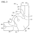
- a bracket generally designated as reference numeral 10 of the present invention includes a top portion 11 and a bottom portion 12.
- the top portion 11 and the bottom portion 12 of each bracket 10 slidably engage each other, i.e. they interconnect permitting transverse (lateral) engagement of the top portion 11 with the bottom portion 12.
- Each bracket 10 has a plurality of projections which engage in a mating fashion in corresponding complementary shaped channels. In the illustrated embodiment shown in FIGS.
- each bracket 10 suitably has projections 13, 14 on the top portion 11 which engage in a mating fashion in correspondingly shaped complementary channels 15, 16, respectively, in the bottom portion 12 of the bracket, and has projections 17, 18 in the bottom portion of the bracket 12 which engage in a mating fashion in correspondingly shaped channels 19, 20, respectively, in the top portion 11 of the bracket.
- the top portion 11 is slid in a transverse (longitudinal/lateral) manner into the bottom portion 12 of the bracket 10.
- the projections 13, 14, 17, and 18 and channels 15, 16, 19 and 20 are in the nature of interlocking rounded joints.
- the bottom portion 12 suitably has a first single projection (17 or 18) and a first single channel (15 or 16)
- the top portion 11 suitably has a single corresponding complementary shaped channel (19 or 20) to engagingly mate with the first single projection (17 or 18) and has a corresponding single complementary shaped projection (13 or 14) to engagingly mate with the first single channel (15 or 16) of the bottom portion.
- four projections 13, 14, 17, and 18 with their corresponding channels 15, 16, 19 and 20 are shown, more projections and associated corresponding complementary shaped channels may be used.
- Other types of combinations of other shaped projections and corresponding complementary shaped channels can be envisioned by those of ordinary skill in the art and are encompassed by the present invention.
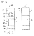
- the top portion 11 of the bracket 10 includes a front face 21, a back face 24, two end walls, 22 and 23, respectively, which extend downwardly from the front face 21 to back face 24, and two end wall edges 40 and 41, respectively.
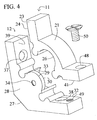
- the front face 21 of the top portion 11 also includes a first fastener aperture 48, that, when the top portion 11 and bottom portion 12 of the bracket 10 are aligned, brings fastener aperture 48 into alignment with a second fastener aperture 49 in the bottom portion 12.
- the first and second fastener apertures, 48, 49 are dimensioned to receive a bracket fastener screw 50 which secures the top portion 11 and the bottom portions 12 of the bracket 10 together.
- the back face 24 of the top portion 11 has a stair rod receiving portion 26.
- the bottom portion 12 of the stair bracket 10 includes a front face 39, a back face 27 and two end walls 28 and 31, respectively.
- End wall 28 is an outside end wall extending upwardly from the back face 27.
- End wall 31 is an inside end wall extending upwardly from the back face 27.
- Outside end wall 28 has an outside end wall edge 29, and an inside surface 30.
- Inside end wall 31 has an inside end wall edge 32, and a stair rod-receiving portion 33.
- the stair rod-receiving portion 33 is adjacent to the inside surface 30 of the outside end wall 28 and extends from inside surface 30 to the inside end wall 31.
- the inside end wall 31 is spaced apart from and generally parallel to the outside end wall 28.
- outside end wall 28 has an aperture 34 therethrough, suitably dimensioned to permit passage of either a threaded finial fastener 70 which engages with a "female" finial 72, or the fastening portion 74 of a "male” finial 76.
- the front face 39 of the bottom portion 12 of the stair rod bracket 10 also includes a pair of mounting apertures 37, 38, respectively, therethrough for accepting fasteners (screws, nails, bolts, or the like) to fasten the bottom portion 12 of the bracket 10 to a stair tread and a stair riser of a step of a staircase.
- fasteners screws, nails, bolts, or the like
- the outside end wall edge 29 of the bottom portion 12 and the corresponding end wall edge 41 of the top portion 11 are complementary in shape, such that these edges 29, 41 abut against each other when the top portion 11 of the bracket 10 is slid into the bottom portion 12 of the bracket 10.
- the edges 29 and 41 engage in a mating fashion.
- the inside end wall edge 32 of the bottom portion 12 of the bracket 10 and the end wall edge 40 of the top portion 11 of the bracket 10 are complementary in shape, such that the edges 32, 40 abut against each other (except for the stair rod receiving portions 26, 33) when the top portion 11 of the bracket 10 is slid into the bottom portion 12 of the bracket 10.
- the edges 32 and 40 engage in a mating fashion, except for the stair rod receiving portions 26, 33.
- the stair rod receiving portions 26, 33 when the two portions 11 and 12 are combined to provide a bracket 10, create a rod receiving enclosure 42 which is sufficiently dimensioned to hold a portion of a stair rod 60 within the bracket 10.
- the transverse (lateral) travel of the rod 60 between the pair of brackets 10 is limited by the inside surface 30 of the outside end wall 28 of the bottom portion 12 of the bracket 10.
- an end of a rod 62 abuts against the inside surface 30, of the outside end wall 28 of the bottom portion 12 of the end bracket 10.
- the rod can contain an aperture 64 which is aligned with the aperture 34 of the outside end wall 28 and is dimensioned to accept the male fastening portion 74 of a finial 72. The insertion of the male fastening portion 74 of the finial 72 through the finial fastener aperture 34, holds the rod to the stair rod bracket 10.
- the abutting relationships of the pairs of edges 29, 41 and 32, 40 create a uni-body bracket construction that is unique to any prior art stair rod bracket and to any prior art stair rod set.
- the uni-body construction achieves a more sturdy construction of any previous stair rod set.
- the sturdiness creates a more secure installation of the stair carpet retaining rod 10, and hence, a safer installation of the stair rod set.
- bracket 10 which is very easy to assemble and disassemble. This is important because the structure of the bracket 10 permits the easy assembly/disassembly of a stair rod set, the easy removal of the top portion 11 of the bracket 10 for cleaning and polishing and the easy replacement of the top portion 11 of the bracket 10. No longer must the user/customer, carry solvents and polishing tools to the staircase to clean the top portions 11 of the bracket 10.
- the top portions 11 of the brackets 10 are easily removed from the bottom portion 12 of the brackets 10 by removing the bracket fastener screw 50 and sliding the top portion 11 in a transverse lateral direction, and the finials are loosened and removed.
- the bracket top portion 11 may then be collected and carried to a more convenient location than the staircase, to clean and polish them.
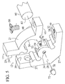
- FIGS. 5-6 Shown in FIGS. 5-6 is a stair rod set, specifically, a stair rod set having a stair carpet retaining rod 60, a pair of finials (72 or 76), and a pair of slidably interconnecting stair rod brackets 10, according to the present invention.
- the rod 60, the finials (72 or 76) and the brackets 10 are preferably made of metals, such as, but not limited to, brass, bronze, copper, aluminum, iron or steel or alloys thereof, and is most suitably made of brass.
- the brackets 10 can also be crafted out of wood or plastic.
- the brackets 10 are carved from a single mass of metal, most suitably brass. This provides an ease of manufacture over two-piece stair brackets containing two separately molded portions. Brackets of such manufacture often have difficulty fitting together due to variations in the separate molds. When the portions are carved out of a single piece of metal, the portions fit together near seamlessly.
- Stair carpeting retaining rods 60 are known and are elongate in shape with opposed ends. These rods 60 have either a hollow core (often referred to as a hollow core-type rod) or a solid core (often referred to as a solid core-type rod). Stair carpeting retaining rods 60 are also known to come in various cross sectional shapes, such as circular, triangular, square, etc. Rods 60 are of a length sufficient to extend beyond a width of a carpet runner which is to be releasable affixed to a step of a staircase.
- One embodiment of the stair carpet retaining rod 60 contains an aperture 64 at each opposing end 62.
- the apertures are suitably dimensioned to accept a fastening means extending from the finial 74.
- These rods 60 are also either of a solid core type having a solid metal cross section (i.e., a solid core) or of a hollow core type having a hollow core surrounded by a rod wall end.
- the finals used in the present invention can either be a "male" finial 76 having a fastener projection 74, or a "female" finial 72 having a fastener receiving aperture 78.
- a male finial 76 the male fastening portion 74 of the finial is of a length sufficient to be inserted into the bracket 10, securing it to the bracket.
- the male finial 74 can be inserted through the aperture 34 of the bracket 10 so as to engage with an aperture 64 in the end of the rod 60, thereby fastening the bracket 10 to the rod 60.
- a finial fastener 70 of a length sufficient to be inserted through the aperture 34 aperture secures the female finial 72 to the bracket 10.
- the pair of slidably interconnecting stair rod brackets 10 are disposed with one bracket 10 of the pair fastened at each end of the rod 60, when the stair rod set is assembled.
- the pair of brackets comprise a right side stair bracket and a left side stair bracket. While the top potion of the bracket is the same in both the right and left sided stair rod brackets, the two bottom portions are constructed as mirror images of each other.
- mirror image is meant herein throughout that the parts of the two brackets are arranged with the reversal of right and left as would appear if seen in a mirror.
- the bottom portion 12 of the bracket 10 may be used with interchangeable top portions 11.
- the top portions 11 are constructed identically to each other but, differ from each other in bearing decorative indicia, or alternatively no indicia, on the front face. Where no indicia is applied to the front face 21, a clean unadorned appearance free from any mechanical apertures or marks is achieved. Where indicia is applied, the indicia may be engraved or etched, or otherwise affixed to the front face.
- the top portion 11 is suitably custom engraved to the user/customer's specification and can be changed with other top portions 11 to meet a user/customer's changing interior design schemes.
- This feature of the present invention permits the user/consumer to change the decorative look of the staircase by replacing only the top portion 11 of the bracket.
- This feature of top portion 11 interchangeability saves the user/customer money because only the top portion 11 of the bracket 10 bearing the indicia desired, needs to be purchased.
- This feature also protects the staircase since the bottom portion 12 does not need to be replaced, thereby preventing extra holes in the staircase where the bottom portion 12 had been affixed.
- a stair rod bracket kit contains a plurality of top 11 and bottom portions 12. Fasteners may be included in the kit. The kit may be sold to outfit just the right side stair bracket, or just the left side stair bracket, or the kit may be sold to outfit both the right side stair bracket and the left side stair bracket.
- a stair rod kit may contain a plurality of top portions 11, at least one left side stair bracket bottom portion 12, a stair carpet retaining rod 60, at lease one right side stair bracket bottom portion 12, and a pair of finials (72 or 76). Fasteners may be also be included in the kit.
- the bracket and the stair rod set are assembled according to the steps of the following method.
- the carpet runner is arranged on the steps of the staircase.
- a pair of brackets 10 is needed for each side of each step of the staircase.
- One bracket 10 of the pair of brackets to be used on a step is affixed to the step first.
- the left side stair bracket is fixed to the step; alternatively, the right side stair bracket could be affixed to the step first.
- the bottom portion 12 of the left side stair bracket is positioned on the step to one side of the carpet runner and secured to the step by affixing fasteners through the aperture 38 in the bottom portion 12 of the bracket 10.
- the top portion 11 of the left side stair bracket is held to the left or right of the bottom portion 12 and the projections 13, 14, 17 and 18 are aligned with complementary shaped channels - 19, 20, 15 and 16. Once aligned, the top portion 11 is slid transversely (e.g., longitudinally or sideways) to the right or left, this movement positions and engages the top portion 11 in a mating fashion on top of the bottom portion 12 so that the pairs of edges abut and engage in a mating fashion.
- the top 11 and bottom portion 12 of the bracket 10 are fastened together by the bracket fastener screw 50 which engages with the first fastener aperture 48 and the second fastener 49, of the top 11 and bottom portion 12 respectively. The finial is then attached to the bracket.
- the male fastening member 74 of the finial is threaded though the aperture 34. If a female finial 72 is used, a finial fastener 70 is threaded through the aperture 34 connecting the female finial 72 to the bracket 10.
- One end of rod 60 is placed in the rod receiving enclosure 42 and the rod is moved transversely so that the end of the rod 60 abuts the inside surface 30 of the outer end wall 28.
- the male fastening portion of the finial 74 can be further threaded into an aperture 64 at the end of the rod 60 and fastened therein.
- the male fastening member 76 of the finial fastens the stair bracket 10 to the rod 60.
- the rod 60 in this position extends across the carpet runner.
- the bottom portion 12 of the right side stair bracket is then positioned on the same step at a suitable distance from the left side stair bracket and to the right of the carpet runner.
- the bottom portion 12 of the right side stair bracket is secured to the step by affixing fasteners through the aperture 38 in the bottom portion 12 of the bracket 10.
- the other end (the non-fastened end) of the rod 60 is positioned into the rod receiving portion 33 of the inside end wall 31 of the bottom portion 12.
- the top portion 11 of the right side stair bracket is held to the right or left of the bottom portion 12 and the projections 13, 14, 17 and 18 are aligned with the respective complementary shaped channels 19, 20, 15 and 16.
- the top portion is slid transversely (longitudinally or sideways) to the right or left, this movement positions and engages the top portion 11 on top of the bottom portion 12 so that the pairs of edges abut.
- the top 11 and bottom 12 portion of the bracket 10 are fastened together by the bracket fastener screw 50 which engages with the first fastener aperture 48 and the second fastener, aperture 49 of the top 11 and bottom 12 portion respectively.
- the rod receiving portions (26 and 33) form the rod receiving enclosure 42 which is suitably dimensioned to receive the rod 60.
- the second finial portion (72 or 76) is then secured to the bracket 10. This action fastens the stair bracket 10 to the rod 60 and completes the assembly of the stair rod set. The method of assembly is repeated for each step of the staircase.
- the process is conducted in reverse order.
- the bracket fastener screw 50 is unfastened and removed.
- the brackets 10 are slid to disengage them.
- the bottom portions 12 of the left side stair bracket and of the right side stair bracket are left fastened to the step.
- the finials (72 or 76) are then unfastened and removed.
- the assembly steps are repeated for reassembling the bracket 10 and the stair rod set, except for the step of fastening the bottom portion 12 of the bracket 10 to the step, which is not needed.
- the steps in the method of assembly are identical to those discussed above, except that prior to the method steps of positioning the top portion 11 on the bottom portion 12 of the respective bracket, one of a plurality of top portions 11 is selected by the user/consumer to be used. Likewise the method of disassembly is as previously stated herein throughout.
Landscapes
- Steps, Ramps, And Handrails (AREA)
- Handcart (AREA)
Claims (6)
- Teppichstangen-Halteklammer, umfassend:einen oberen Teil (11) mit einer vorderen Fläche (21), einer hinteren Fläche (24), zwei Endwänden (22, 23), die sich jeweils von der vorderen Fläche des oberen Teils zur hinteren Fläche des oberen Teils nach unten erstrecken, einen ersten Vorsprung (13) und einen ersten Kanal (19);einen unteren Teil (12) mit einer vorderen Fläche (39), einer hinteren Fläche (27), einem ersten Vorsprung (17), einem ersten Kanal (15), einer Außenendwand (28), die sich von der hinteren Fläche des unteren Teils nach oben erstreckt, wobei die Außenendwand eine Fertigbefestigungsöffnung (34) aufweist, einer Innenendwand (31), die sich von der hinteren Fläche des unteren Teils nach oben erstreckt, und einem Teppichstangen-Aufnahmeabschnitt (33);worin der erste Vorsprung (13) des oberen Teils (11) zur Aufnahme im ersten Kanal (15) des unteren Teils ausgebildet ist und der erste Vorsprung (17) des unteren Teils zur Aufnahme im ersten Kanal des oberen Teils ausgebildet ist und
worin die Aufnahme des ersten Vorsprungs des oberen Teils im ersten Kanal des unteren Teils und des ersten Vorsprungs des unteren Teils im ersten Kanal des oberen Teils den quer verlaufenden Eingriff des oberen Teils in den unteren Teil ermöglicht. - Teppichstangen-Halteklammer nach Anspruch 1, worin der obere Teil ferner einen zweiten Vorsprung und einen zweiten Kanal umfasst und der untere Teil ferner einen zweiten Vorsprung und einen zweiten Kanal umfasst;
worin der zweite Vorsprung des oberen Teils zur Aufnahme im zweiten Kanal des unteren Teils ausgebildet ist und der zweite Vorsprung des unteren Teils zur Aufnahme im zweiten Kanal des oberen Teils ausgebildet ist und
worin die Aufnahme des zweiten Vorsprungs des oberen Teils im zweiten Kanal des unteren Teils und des zweiten Vorsprungs des unteren Teils im zweiten Kanal des oberen Teils den quer verlaufenden Eingriff des oberen Teils in den unteren Teil ermöglicht. - Teppichstangen-Halteklammer nach einem der vorangegangenen Ansprüche, worin die obere Fläche des oberen Teils ferner eine erste Befestigungsöffnung umfasst und die obere Fläche des unteren Teils ferner eine Anbringungsöffnung und eine zweite Befestigungsöffnung umfasst und
sich eine Befestigungsvorrichtung durch die erste und zweite Befestigungsöffnung hindurchbewegt und den oberen Teil an dem unteren Teil befestigt. - Teppichstangen-Halteklammer nach einem der vorangegangenen Ansprüche,
worin die Vorsprünge des oberen Teils und des unteren Teils abgerundet sind. - Teppichstangen-Halteklammer nach einem der Ansprüche 2-4, worin der erste Vorsprung des oberen Teils an den ersten Kanal des oberen Teils angrenzt und der zweite Vorsprung des oberen Teils an den zweiten kanal des oberen Teils angrenzt und
worin der erste Vorsprung des unteren Teils an den ersten Kanal des unteren Teils angrenzt und der zweite Vorsprung des unteren Teils an den zweiten Kanal des unteren Teils angrenzt. - Teppichstangen-Halteklammer nach einem der vorangegangenen Ansprüche,
worin der obere Teil eine erste Endwandkante und eine zweite Endwandkante aufweist, wobei die Außenendwand des oberen Teils eine Außenendwandkante und eine Innenoberfläche aufweist,
wobei die Innenendwand des unteren Teils eine Innenendwandkante aufweist und der Teppichstangen-Aufnahmeabschnitt an die Innenoberfläche der Außenendwand angrenzt und sich von der Innenoberfläche zur Innenendwand erstreckt und
wobei die Außenendwandkante des unteren Teils eine zur ersten Endwandkante des oberen Teils ergänzende Form aufweist, so dass, wenn der obere Teil über den unteren Teil gleitet, die erste Endwandkante des oberen Teils und die Außenendwandkante des unteren Teils in einer zusammenpassenden Weise ineinander eingreifen.
Applications Claiming Priority (3)
| Application Number | Priority Date | Filing Date | Title |
|---|---|---|---|
| US31119201P | 2001-08-09 | 2001-08-09 | |
| US311192P | 2001-08-09 | ||
| PCT/US2002/025293 WO2003013320A2 (en) | 2001-08-09 | 2002-08-09 | Stair rod bracket |
Publications (3)
| Publication Number | Publication Date |
|---|---|
| EP1450652A2 EP1450652A2 (de) | 2004-09-01 |
| EP1450652A4 EP1450652A4 (de) | 2006-08-23 |
| EP1450652B1 true EP1450652B1 (de) | 2008-05-21 |
Family
ID=23205807
Family Applications (1)
| Application Number | Title | Priority Date | Filing Date |
|---|---|---|---|
| EP02768468A Expired - Lifetime EP1450652B1 (de) | 2001-08-09 | 2002-08-09 | Teppichstangenhalteklammer |
Country Status (5)
| Country | Link |
|---|---|
| US (2) | US20040231097A1 (de) |
| EP (1) | EP1450652B1 (de) |
| AU (1) | AU2002331028A1 (de) |
| DE (1) | DE60226769D1 (de) |
| WO (1) | WO2003013320A2 (de) |
Families Citing this family (13)
| Publication number | Priority date | Publication date | Assignee | Title |
|---|---|---|---|---|
| US20050252159A1 (en) * | 2004-04-19 | 2005-11-17 | Aboolhassan Zoroufy | Adaptive decorative stair rod and brackets |
| US7080426B2 (en) * | 2004-05-13 | 2006-07-25 | Brass Elegans, Inc. | Carpet stair rod set |
| US20070241251A1 (en) * | 2006-03-31 | 2007-10-18 | Stair Hold, Inc. | Bottom mounted stair rod bracket |
| US20080244893A1 (en) * | 2007-04-04 | 2008-10-09 | Zoroufy D Hussein | Steel core brass stair rod |
| WO2009036238A1 (en) * | 2007-09-12 | 2009-03-19 | Stair-Hold Inc. | Stair rod bracket set with collar sections |
| US8925148B2 (en) | 2012-03-06 | 2015-01-06 | Ronald Prezner | Rod brackets and related systems and methods |
| USD734658S1 (en) | 2012-03-06 | 2015-07-21 | Ronald Prezner | Rod bracket |
| US8359707B1 (en) | 2012-03-06 | 2013-01-29 | Decorative Hardware Studio Inc. | Rod brackets and related systems and methods |
| US11272801B2 (en) * | 2014-01-28 | 2022-03-15 | Kenney Manufacturing Company | Curtain rod return bracket |
| USD761641S1 (en) * | 2015-05-08 | 2016-07-19 | Revolution Display, Llc | Connection member for a modular support frame |
| USD760581S1 (en) * | 2015-05-08 | 2016-07-05 | Revolution Display, Llc | Connection member for a modular support frame |
| USD761096S1 (en) * | 2015-05-08 | 2016-07-12 | Revolution Display, Llc | Connection member for a modular support frame |
| USD831463S1 (en) * | 2016-11-03 | 2018-10-23 | Erik Granberg | Handle boss bracket |
Family Cites Families (45)
| Publication number | Priority date | Publication date | Assignee | Title |
|---|---|---|---|---|
| US144759A (en) | 1873-11-18 | Improvement in stair-rod fasteners | ||
| US484708A (en) * | 1892-10-18 | William gates | ||
| US304951A (en) | 1884-09-09 | Dlesex | ||
| US391841A (en) | 1888-10-30 | Stair-rod securer | ||
| US701394A (en) * | 1901-08-24 | 1902-06-03 | William Richards | Stair-rod fastener. |
| US737143A (en) * | 1903-02-18 | 1903-08-25 | Thomas C Richards | Stair-rod fastener. |
| US805307A (en) * | 1905-07-03 | 1905-11-21 | John Mallen | Rod-fastener for stairways. |
| GB190525921A (en) * | 1905-12-13 | 1906-10-18 | Ernest Jones | Improvements in Stair Rod Eyes. |
| GB190625921A (en) | 1906-11-16 | 1907-11-16 | Alfred Edward French | Improvements in or connected with Garden Syringes. |
| US869492A (en) * | 1907-02-19 | 1907-10-29 | William Henry Joyner | Stair-rod fastener. |
| US899377A (en) * | 1908-03-31 | 1908-09-22 | Clarence E Billings | Carpet-fastener. |
| US1373148A (en) * | 1920-03-20 | 1921-03-29 | Phillips Edward St John | Stair-eye to facilitate the laying down and taking up of stair-carpets |
| GB171229A (en) * | 1920-08-31 | 1921-11-17 | Albert Edward Shiner | Improvements in eyes or brackets for stair rods, curtain poles and the like |
| US1624392A (en) * | 1923-08-01 | 1927-04-12 | Cleverly Edwin George | Fixing for rods, poles, and the like |
| GB414793A (en) | 1933-02-23 | 1934-08-16 | J R Pearson Birmingham Ltd | Improvements in stair rod eyes |
| CH299315A (de) * | 1952-02-21 | 1954-06-15 | Hofmann Jun Willy | Einrichtung zum Festhalten von Teppichläufern auf Treppen. |
| US3487496A (en) | 1967-02-13 | 1970-01-06 | Charles W Guyton | Plastic doorknob |
| US3543329A (en) | 1969-01-30 | 1970-12-01 | Gen Motors Corp | Decorative knob |
| US4014122A (en) | 1975-09-22 | 1977-03-29 | Woods Oscar J | Paperweight with screw threaded bottom cap |
| USD304951S (en) * | 1986-01-30 | 1989-12-05 | Canon Kabushiki Kaisha | Microfilm reader printer |
| US5008551A (en) | 1989-05-16 | 1991-04-16 | Randolph Timothy T | Phosphorescent luminous door knobs cover |
| USD340404S (en) * | 1991-12-06 | 1993-10-19 | The Decorative Hardware Studio, Inc. | Finial |
| USD342437S (en) * | 1991-12-06 | 1993-12-21 | The Decorative Hardware Studio, Inc. | Bracket for a stair carpet retaining rod |
| US5519972A (en) | 1993-09-03 | 1996-05-28 | The Grigoleit Company | Decorative product having a decorative strip |
| US5499427A (en) | 1994-09-02 | 1996-03-19 | Blaser Die Casting Co. | Drawer knob assembly |
| US5598652A (en) | 1994-09-14 | 1997-02-04 | Nurre; David F. | Lamp with changeable display base |
| US5657886A (en) | 1995-07-28 | 1997-08-19 | Creative Resource, Inc. | Decorative assembly including a transparent sleeve |
| US5690239A (en) | 1996-05-24 | 1997-11-25 | Ballard; Donald M. | Multi-purpose columnar support |
| USD391841S (en) * | 1997-03-13 | 1998-03-10 | Howe Furniture Corporation | Furniture roller |
| US6082877A (en) | 1998-03-06 | 2000-07-04 | Hughes; Mary Virginia | Indoor/outdoor lighting assembly |
| US5960516A (en) * | 1998-05-04 | 1999-10-05 | Zoroufy; Aboolhasan | Stair rod bracket and stair rod set |
| US6435700B1 (en) | 2000-08-22 | 2002-08-20 | Michael Graham | Adjustable lamp shade |
| US6338179B1 (en) * | 2000-09-05 | 2002-01-15 | Warren Blackstone | Carpet rod brackets and carpet rod assemblies using the same |
| US6701747B2 (en) | 2001-10-18 | 2004-03-09 | Heart & Company | Decorative articles with interchangeable modules |
| US6839936B2 (en) * | 2001-11-27 | 2005-01-11 | Benjamin I. Kaufman | Latching stair rod assembly |
| US6836997B2 (en) | 2002-07-31 | 2005-01-04 | John F. Cramsey | Adjustable buoyancy floating fish lure |
| DE10239983A1 (de) | 2002-08-27 | 2004-03-04 | Russler, Theodor | Zaun |
| USD484708S1 (en) | 2002-10-25 | 2004-01-06 | Patrick O. Kraker | Pattern for a synthetic thermoset solid surface material |
| USD493359S1 (en) | 2003-12-08 | 2004-07-27 | Beme International, Llc | Knob finial |
| TWM267967U (en) | 2004-12-17 | 2005-06-21 | Hsiao-Wei Nien | Decoration head structure at terminal of window curtain rod |
| USD676245S1 (en) | 2010-03-30 | 2013-02-19 | Colgate-Palmolive Company | Oral care implement |
| USD781785S1 (en) | 2012-09-11 | 2017-03-21 | Apple Inc. | Adapter |
| TWD156422S (zh) | 2012-10-15 | 2013-10-21 | 林梅珊 | 牙刷杯組架 |
| USD718131S1 (en) | 2013-10-31 | 2014-11-25 | Biomed Packaging Systems, Inc. | Applicator dispensing head |
| USD869492S1 (en) | 2018-07-09 | 2019-12-10 | Scripps Networks, Llc | Display screen with graphical user interface |
-
2002
- 2002-08-09 AU AU2002331028A patent/AU2002331028A1/en not_active Abandoned
- 2002-08-09 EP EP02768468A patent/EP1450652B1/de not_active Expired - Lifetime
- 2002-08-09 WO PCT/US2002/025293 patent/WO2003013320A2/en not_active Ceased
- 2002-08-09 DE DE60226769T patent/DE60226769D1/de not_active Expired - Lifetime
- 2002-08-09 US US10/486,296 patent/US20040231097A1/en not_active Abandoned
-
2006
- 2006-05-01 US US11/380,995 patent/US7461431B2/en not_active Expired - Fee Related
Also Published As
| Publication number | Publication date |
|---|---|
| DE60226769D1 (de) | 2008-07-03 |
| EP1450652A2 (de) | 2004-09-01 |
| AU2002331028A1 (en) | 2003-02-24 |
| EP1450652A4 (de) | 2006-08-23 |
| WO2003013320A3 (en) | 2004-06-24 |
| WO2003013320A2 (en) | 2003-02-20 |
| US20040231097A1 (en) | 2004-11-25 |
| US20060191100A1 (en) | 2006-08-31 |
| US7461431B2 (en) | 2008-12-09 |
Similar Documents
| Publication | Publication Date | Title |
|---|---|---|
| US5960516A (en) | Stair rod bracket and stair rod set | |
| US7461431B2 (en) | Stair rod bracket | |
| US5230127A (en) | Personalized face cremation urn | |
| US7886501B2 (en) | Door edge construction | |
| US20100199482A1 (en) | Method Of Forming Sheet Metal Casket | |
| US6543103B1 (en) | Thematic casket and urn assembly | |
| US20070101655A1 (en) | Door Edge Construction | |
| DE102013105156A1 (de) | Brillenauslegesystem | |
| EP1527672A3 (de) | Fadenschneider mit zerlegbarem Heft | |
| EP0917837A3 (de) | Trennbarer unterer Endanschlag für Reissverschlüsse | |
| US11261616B2 (en) | Modular fence system | |
| US6532633B2 (en) | Zipper slider | |
| USD512298S1 (en) | Pull | |
| EP1103771A3 (de) | Kältegerätetür | |
| US20130008616A1 (en) | Cordless window curtain | |
| US7168474B2 (en) | Decorative device comprised of modular interchangeable components | |
| US8925148B2 (en) | Rod brackets and related systems and methods | |
| US349631A (en) | William cutts | |
| EP0863370B1 (de) | Abdeckvorrichtung und Heizkörper mit einer solchen Abdeckvorrichtung | |
| US20240268338A1 (en) | Attachment device for an animal crate | |
| DE102013105159A1 (de) | Brillenauslegesystem | |
| WO2009036238A1 (en) | Stair rod bracket set with collar sections | |
| US338978A (en) | Stair-rod securer | |
| CN2247146Y (zh) | 保特瓶提带 | |
| JP2005200899A (ja) | 引手およびこの引手を備えた建具 |
Legal Events
| Date | Code | Title | Description |
|---|---|---|---|
| PUAI | Public reference made under article 153(3) epc to a published international application that has entered the european phase |
Free format text: ORIGINAL CODE: 0009012 |
|
| 17P | Request for examination filed |
Effective date: 20040219 |
|
| AK | Designated contracting states |
Kind code of ref document: A2 Designated state(s): AT BE BG CH CY CZ DE DK EE ES FI FR GB GR IE IT LI LU MC NL PT SE SK TR |
|
| AX | Request for extension of the european patent |
Extension state: AL LT LV MK RO SI |
|
| A4 | Supplementary search report drawn up and despatched |
Effective date: 20060720 |
|
| 17Q | First examination report despatched |
Effective date: 20061206 |
|
| 17Q | First examination report despatched |
Effective date: 20061206 |
|
| GRAP | Despatch of communication of intention to grant a patent |
Free format text: ORIGINAL CODE: EPIDOSNIGR1 |
|
| GRAS | Grant fee paid |
Free format text: ORIGINAL CODE: EPIDOSNIGR3 |
|
| GRAA | (expected) grant |
Free format text: ORIGINAL CODE: 0009210 |
|
| AK | Designated contracting states |
Kind code of ref document: B1 Designated state(s): BE DE FR GB |
|
| REG | Reference to a national code |
Ref country code: GB Ref legal event code: FG4D |
|
| REF | Corresponds to: |
Ref document number: 60226769 Country of ref document: DE Date of ref document: 20080703 Kind code of ref document: P |
|
| PLBE | No opposition filed within time limit |
Free format text: ORIGINAL CODE: 0009261 |
|
| STAA | Information on the status of an ep patent application or granted ep patent |
Free format text: STATUS: NO OPPOSITION FILED WITHIN TIME LIMIT |
|
| 26N | No opposition filed |
Effective date: 20090224 |
|
| PGFP | Annual fee paid to national office [announced via postgrant information from national office to epo] |
Ref country code: DE Payment date: 20100827 Year of fee payment: 9 Ref country code: FR Payment date: 20100831 Year of fee payment: 9 |
|
| PGFP | Annual fee paid to national office [announced via postgrant information from national office to epo] |
Ref country code: BE Payment date: 20100825 Year of fee payment: 9 |
|
| BERE | Be: lapsed |
Owner name: ZOROUFY, ABOOLHASSAN Effective date: 20110831 Owner name: ZOROUFY, HUSSEIN Effective date: 20110831 |
|
| REG | Reference to a national code |
Ref country code: FR Ref legal event code: ST Effective date: 20120430 |
|
| PG25 | Lapsed in a contracting state [announced via postgrant information from national office to epo] |
Ref country code: BE Free format text: LAPSE BECAUSE OF NON-PAYMENT OF DUE FEES Effective date: 20110831 |
|
| REG | Reference to a national code |
Ref country code: DE Ref legal event code: R119 Ref document number: 60226769 Country of ref document: DE Effective date: 20120301 |
|
| PG25 | Lapsed in a contracting state [announced via postgrant information from national office to epo] |
Ref country code: FR Free format text: LAPSE BECAUSE OF NON-PAYMENT OF DUE FEES Effective date: 20110831 |
|
| PG25 | Lapsed in a contracting state [announced via postgrant information from national office to epo] |
Ref country code: DE Free format text: LAPSE BECAUSE OF NON-PAYMENT OF DUE FEES Effective date: 20120301 |
|
| PGFP | Annual fee paid to national office [announced via postgrant information from national office to epo] |
Ref country code: GB Payment date: 20190814 Year of fee payment: 18 |
|
| GBPC | Gb: european patent ceased through non-payment of renewal fee |
Effective date: 20200809 |
|
| PG25 | Lapsed in a contracting state [announced via postgrant information from national office to epo] |
Ref country code: GB Free format text: LAPSE BECAUSE OF NON-PAYMENT OF DUE FEES Effective date: 20200809 |