EP1451024B1 - Logement de roue situe sur un corps d'essieu destine a des vehicules - Google Patents
Logement de roue situe sur un corps d'essieu destine a des vehicules Download PDFInfo
- Publication number
- EP1451024B1 EP1451024B1 EP02791734A EP02791734A EP1451024B1 EP 1451024 B1 EP1451024 B1 EP 1451024B1 EP 02791734 A EP02791734 A EP 02791734A EP 02791734 A EP02791734 A EP 02791734A EP 1451024 B1 EP1451024 B1 EP 1451024B1
- Authority
- EP
- European Patent Office
- Prior art keywords
- axle
- axle tube
- wheel bearing
- end section
- wheel
- Prior art date
- Legal status (The legal status is an assumption and is not a legal conclusion. Google has not performed a legal analysis and makes no representation as to the accuracy of the status listed.)
- Expired - Lifetime
Links
- 238000003466 welding Methods 0.000 claims description 4
- 238000004519 manufacturing process Methods 0.000 abstract description 4
- 238000000034 method Methods 0.000 abstract 1
- 230000002787 reinforcement Effects 0.000 description 5
- 238000005452 bending Methods 0.000 description 2
- 239000000853 adhesive Substances 0.000 description 1
- 230000001070 adhesive effect Effects 0.000 description 1
- 239000012876 carrier material Substances 0.000 description 1
- 150000001875 compounds Chemical class 0.000 description 1
- 230000007797 corrosion Effects 0.000 description 1
- 238000005260 corrosion Methods 0.000 description 1
- 230000005012 migration Effects 0.000 description 1
- 238000013508 migration Methods 0.000 description 1
Images

Classifications
-
- B—PERFORMING OPERATIONS; TRANSPORTING
- B60—VEHICLES IN GENERAL
- B60B—VEHICLE WHEELS; CASTORS; AXLES FOR WHEELS OR CASTORS; INCREASING WHEEL ADHESION
- B60B35/00—Axle units; Parts thereof ; Arrangements for lubrication of axles
- B60B35/004—Mounting arrangements for axles
- B60B35/006—Mounting arrangements for axles with mounting plates or consoles fitted to axles
-
- B—PERFORMING OPERATIONS; TRANSPORTING
- B60—VEHICLES IN GENERAL
- B60B—VEHICLE WHEELS; CASTORS; AXLES FOR WHEELS OR CASTORS; INCREASING WHEEL ADHESION
- B60B35/00—Axle units; Parts thereof ; Arrangements for lubrication of axles
- B60B35/02—Dead axles, i.e. not transmitting torque
-
- B—PERFORMING OPERATIONS; TRANSPORTING
- B60—VEHICLES IN GENERAL
- B60B—VEHICLE WHEELS; CASTORS; AXLES FOR WHEELS OR CASTORS; INCREASING WHEEL ADHESION
- B60B2310/00—Manufacturing methods
- B60B2310/30—Manufacturing methods joining
- B60B2310/305—Manufacturing methods joining by screwing
-
- B—PERFORMING OPERATIONS; TRANSPORTING
- B60—VEHICLES IN GENERAL
- B60B—VEHICLE WHEELS; CASTORS; AXLES FOR WHEELS OR CASTORS; INCREASING WHEEL ADHESION
- B60B2310/00—Manufacturing methods
- B60B2310/30—Manufacturing methods joining
- B60B2310/306—Manufacturing methods joining by clamping or wedging, e.g. by clamping inserts as joining means
-
- B—PERFORMING OPERATIONS; TRANSPORTING
- B60—VEHICLES IN GENERAL
- B60G—VEHICLE SUSPENSION ARRANGEMENTS
- B60G2206/00—Indexing codes related to the manufacturing of suspensions: constructional features, the materials used, procedures or tools
- B60G2206/01—Constructional features of suspension elements, e.g. arms, dampers, springs
- B60G2206/50—Constructional features of wheel supports or knuckles, e.g. steering knuckles, spindle attachments
-
- Y—GENERAL TAGGING OF NEW TECHNOLOGICAL DEVELOPMENTS; GENERAL TAGGING OF CROSS-SECTIONAL TECHNOLOGIES SPANNING OVER SEVERAL SECTIONS OF THE IPC; TECHNICAL SUBJECTS COVERED BY FORMER USPC CROSS-REFERENCE ART COLLECTIONS [XRACs] AND DIGESTS
- Y10—TECHNICAL SUBJECTS COVERED BY FORMER USPC
- Y10T—TECHNICAL SUBJECTS COVERED BY FORMER US CLASSIFICATION
- Y10T29/00—Metal working
- Y10T29/49—Method of mechanical manufacture
- Y10T29/49481—Wheel making
- Y10T29/49483—Railway or trolley wheel making
- Y10T29/49485—Multiple part or composite
-
- Y—GENERAL TAGGING OF NEW TECHNOLOGICAL DEVELOPMENTS; GENERAL TAGGING OF CROSS-SECTIONAL TECHNOLOGIES SPANNING OVER SEVERAL SECTIONS OF THE IPC; TECHNICAL SUBJECTS COVERED BY FORMER USPC CROSS-REFERENCE ART COLLECTIONS [XRACs] AND DIGESTS
- Y10—TECHNICAL SUBJECTS COVERED BY FORMER USPC
- Y10T—TECHNICAL SUBJECTS COVERED BY FORMER US CLASSIFICATION
- Y10T29/00—Metal working
- Y10T29/49—Method of mechanical manufacture
- Y10T29/49481—Wheel making
- Y10T29/49483—Railway or trolley wheel making
- Y10T29/49485—Multiple part or composite
- Y10T29/49487—Multiple part or composite with axle or hub
-
- Y—GENERAL TAGGING OF NEW TECHNOLOGICAL DEVELOPMENTS; GENERAL TAGGING OF CROSS-SECTIONAL TECHNOLOGIES SPANNING OVER SEVERAL SECTIONS OF THE IPC; TECHNICAL SUBJECTS COVERED BY FORMER USPC CROSS-REFERENCE ART COLLECTIONS [XRACs] AND DIGESTS
- Y10—TECHNICAL SUBJECTS COVERED BY FORMER USPC
- Y10T—TECHNICAL SUBJECTS COVERED BY FORMER US CLASSIFICATION
- Y10T29/00—Metal working
- Y10T29/49—Method of mechanical manufacture
- Y10T29/49481—Wheel making
- Y10T29/49492—Land wheel
- Y10T29/49496—Disc type wheel
- Y10T29/49497—Assembling wheel disc to rim and hub
-
- Y—GENERAL TAGGING OF NEW TECHNOLOGICAL DEVELOPMENTS; GENERAL TAGGING OF CROSS-SECTIONAL TECHNOLOGIES SPANNING OVER SEVERAL SECTIONS OF THE IPC; TECHNICAL SUBJECTS COVERED BY FORMER USPC CROSS-REFERENCE ART COLLECTIONS [XRACs] AND DIGESTS
- Y10—TECHNICAL SUBJECTS COVERED BY FORMER USPC
- Y10T—TECHNICAL SUBJECTS COVERED BY FORMER US CLASSIFICATION
- Y10T29/00—Metal working
- Y10T29/49—Method of mechanical manufacture
- Y10T29/49481—Wheel making
- Y10T29/49492—Land wheel
- Y10T29/49496—Disc type wheel
- Y10T29/49499—Assembling wheel disc to rim
-
- Y—GENERAL TAGGING OF NEW TECHNOLOGICAL DEVELOPMENTS; GENERAL TAGGING OF CROSS-SECTIONAL TECHNOLOGIES SPANNING OVER SEVERAL SECTIONS OF THE IPC; TECHNICAL SUBJECTS COVERED BY FORMER USPC CROSS-REFERENCE ART COLLECTIONS [XRACs] AND DIGESTS
- Y10—TECHNICAL SUBJECTS COVERED BY FORMER USPC
- Y10T—TECHNICAL SUBJECTS COVERED BY FORMER US CLASSIFICATION
- Y10T29/00—Metal working
- Y10T29/49—Method of mechanical manufacture
- Y10T29/49826—Assembling or joining
- Y10T29/4984—Retaining clearance for motion between assembled parts
-
- Y—GENERAL TAGGING OF NEW TECHNOLOGICAL DEVELOPMENTS; GENERAL TAGGING OF CROSS-SECTIONAL TECHNOLOGIES SPANNING OVER SEVERAL SECTIONS OF THE IPC; TECHNICAL SUBJECTS COVERED BY FORMER USPC CROSS-REFERENCE ART COLLECTIONS [XRACs] AND DIGESTS
- Y10—TECHNICAL SUBJECTS COVERED BY FORMER USPC
- Y10T—TECHNICAL SUBJECTS COVERED BY FORMER US CLASSIFICATION
- Y10T29/00—Metal working
- Y10T29/49—Method of mechanical manufacture
- Y10T29/49826—Assembling or joining
- Y10T29/49947—Assembling or joining by applying separate fastener
- Y10T29/49948—Multipart cooperating fastener [e.g., bolt and nut]
-
- Y—GENERAL TAGGING OF NEW TECHNOLOGICAL DEVELOPMENTS; GENERAL TAGGING OF CROSS-SECTIONAL TECHNOLOGIES SPANNING OVER SEVERAL SECTIONS OF THE IPC; TECHNICAL SUBJECTS COVERED BY FORMER USPC CROSS-REFERENCE ART COLLECTIONS [XRACs] AND DIGESTS
- Y10—TECHNICAL SUBJECTS COVERED BY FORMER USPC
- Y10T—TECHNICAL SUBJECTS COVERED BY FORMER US CLASSIFICATION
- Y10T29/00—Metal working
- Y10T29/49—Method of mechanical manufacture
- Y10T29/49826—Assembling or joining
- Y10T29/49947—Assembling or joining by applying separate fastener
- Y10T29/49963—Threaded fastener
Definitions
- the invention relates to a wheel bearing on a axle designed as an axle tube for vehicles, in particular commercial vehicles, in which the wheel is used e.g. attached via wheel bolts on a rotatably mounted on the stub axle of the axle tube wheel hub and the stub axle is braced as a separate component with an end portion of the axle tube.
- Object of the present invention is therefore to propose a wheel bearing of the type mentioned, which is easy to manufacture and assembly and durable in their function.
- the cylindrical fit unlike that of conical surfaces, is easier to manufacture, durable in function, and easy to disengage. It leads in particular to no widening of the end portion of the axle tube, which is additionally prevented by the radial clamping action of the clamping ring. In addition, much higher forces can be absorbed by this wheel bearing than by conventional flange connections.
- the solution according to the invention is of particular advantage in particular if the brake body which is necessary in any case and which is fixed on the axle body forms the clamping ring, d. H. the clamping ring is part or integral part of the brake carrier. In this way, the brake carrier receives a double function.
- the clamping ring can in the simplest case on both sides of the annular slot each have a penetrated by a threaded bolt clamping flange, wherein the threaded bolt can interact either with an internal thread of a clamping flange or with its own mother.
- aligned longitudinal slot of the end portion of the axle tube and the annular slot both preferably extending axially parallel.
- the clamping flanges z. B be connected to each other at their outer ends via a bridge. In this way, the clamping path can be accomplished only in the elastic region of the clamping ring or brake carrier material.
- the longitudinal slot of the end portion of the axle tube can open at its inner end in an opposite the width of the slot enlarged round hole to securely limit the longitudinal slot in its length.
- At least one screw can be positioned radially on the axle tube by a local reinforcement with internal thread for receiving the screw is provided on the axle tube such that the inner end of the screw engages in a circumferential groove of the stub axle.
- the local reinforcements can also form the conclusion of the longitudinal slots, it can also be one-piece be circumferentially firmly connected to the axle tube.
- the local reinforcement can also be part of the clamping ring.
- the stub axle is flanged at its outer end for axially fixing the wheel bearing to the outside. Since in the wheel bearing according to the invention the wheel bearing itself no longer needs to be disassembled, the wheel bearing can be given a secure fit in the axle stub in this way.
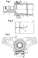
- the wheel bearing according to the invention is provided in accordance with FIG. 1 on an axle body designed as axle tube 1 for vehicles, in particular commercial vehicles.
- the (not shown) wheel is in such a wheel bearing, for example.
- the stub axle 2 is radially clamped as a separate component with the end portion 3 of the axle tube 1.
- the end portion 3 of the axle tube 1 is formed inside cylindrical.
- the end section 3 is equipped with at least one axially parallel longitudinal slot 4.
- the stub axle 2 is fitted with an externally cylindrical connecting portion 5 in the end portion 3 of the axle tube 1, wherein the end portion 3 of the axle tube 1 and the connecting portion 5 of the stub axle 2 by means of at least one seated on the end portion 3 of the axle tube 1, slotted longitudinally through Clamping ring 6 is clamped radially.
- a threaded bolt 8 which with two eye-like clamping flanges 9, 9 cooperates.
- the slot 4 ends the width b in a round hole 11 with this opposite expanded diameter to prevent tearing of the longitudinal slot 4.
- Fig. 3 is also indicated that the clamping flanges 9 can be connected to fully utilize the maximum clamping force of the threaded bolt 8 at their outer ends via a bridge 15.
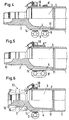
- FIG. 4 illustrates by way of example that, apart from the use of a single clamping ring 6 independent of the brake carrier 10, a further clamping ring 6 ', which is arranged at an axial distance from the first on the axle tube 1, can serve next to the brake carrier 10.
- a further clamping ring 6 ' which is arranged at an axial distance from the first on the axle tube 1
- stub axle 2 may be flanged at its outer end 12 for axially fixing the wheel bearing 13 to the outside. For a permanent securing the wheel bearing 13 is ensured in its axial position.
- Against ingress of moisture between the connecting portion 5 of the stub axle 2 and the end portion 3 of the axle tube 1 may be provided as a seal, an O-ring 14, also it is possible, in particular there to provide a corrosion protection layer. All non-welded columns can also be sealed after assembly with a permanently elastic compound.
- a securing device for the stub axle 2 at the end portion 3 of the axle tube 1 is shown. It is formed by a screwed into an axle tube 1 reinforcement 16 with internal screw screw 17 which protrudes in its securing position with its inner end in a circumferential groove 18 of the stub axle 2 in the illustrated case, for example in the region of the enlarged hole 11 at the end of the slot 4.
Landscapes
- Engineering & Computer Science (AREA)
- Mechanical Engineering (AREA)
- Braking Arrangements (AREA)
- Rolling Contact Bearings (AREA)
- Harvesting Machines For Root Crops (AREA)
- Automatic Cycles, And Cycles In General (AREA)
- Vehicle Body Suspensions (AREA)
- Meat, Egg Or Seafood Products (AREA)
Claims (9)
- Logement de roue sur un corps d'essieu conçu sous la forme d'un tube d'essieu (1) pour des véhicules automobiles, notamment des véhicules utilitaires, dans lequel la roue est fixée, par exemple à l'aide de boulons de roue, sur un moyeu logé pivotant sur la fusée (2) du tube d'essieu (1) et la fusée (2), en tant que pièce séparée, est serré contre une extrémité (3) du tube d'essieu (1), caractérisé en ce que l'extrémité (3) du tube d'essieu (1) est formée à l'intérieur de façon cylindrique et avec au moins une fente longitudinale (4), la fusée (2) est adaptée dans l'extrémité (3) du tube d'essieu (1) avec une section de liaison (5) cylindrique à l'extérieur de façon correspondante et l'extrémité (3) du tube d'essieu (1) est serrée radialement contre la section de liaison (5) de la fusée (2) au moyen d'au moins un collier de serrage (6) placé sur l'extrémité (3) du tube d'essieu (1), lequel collier tendeur est fendu de part en part en direction de la longueur, grâce à quoi une fente de collier (7) est formée.
- Logement de roue selon la revendication 1, caractérisé en ce que le collier tendeur (6) fait partie ou est un élément intégré du flasque de frein (10).
- Logement de roue selon la revendication 1 ou 2, caractérisé en ce que le collier tendeur (6), notamment lorsqu'il est un élément intégré du flasque de frein (10) est pointé pour le positionnement sur l'extrémité (3) du tube d'essieu (1), par exemple au moyen de soudage d'assemblage.
- Logement de roue selon l'une des revendications 1 à 3, caractérisé en ce que la fente longitudinale (4) de l'extrémité (3) du tube d'essieu (1) est alignée avec la fente de collet (7).
- Logement de roue selon l'une des revendications 1 à 4, caractérisé en ce que le collet de serrage (6) présente de chaque côté de la fente de collet (7) une bride de serrage (9) traversée par un boulon fileté (8).
- Logement de roue selon la revendication 5, caractérisé en ce que les brides de serrage (9, 9) sont reliées ensemble par un pont (15).
- Logement de roue selon l'une des revendications 1 à 6, caractérisé en ce que la fente longitudinale (4) de l'extrémité (3) du tube d'essieu (1) débouche par son extrémité intérieure dans un trou rond (11) élargi par rapport à sa largeur de fente (b).
- Logement de roue selon l'une des revendications 1 à 7, caractérisé par au moins un dispositif de sûreté (16, 17, 18) pour la fusée (2) à l'extrémité (3) du tube d'essieu (1).
- Logement de roue selon l'une des revendications 1 à 8, caractérisé en ce que la fusée (2) à son extrémité extérieure (12) est rabattue vers l'extérieure à son extrémité extérieure (12) pour la fixation axiale du roulement de la roue (13).
Applications Claiming Priority (3)
| Application Number | Priority Date | Filing Date | Title |
|---|---|---|---|
| DE20119640U DE20119640U1 (de) | 2001-12-04 | 2001-12-04 | Radlagerung an einem Achskörper für Fahrzeuge |
| DE20119640U | 2001-12-04 | ||
| PCT/EP2002/013468 WO2003047883A1 (fr) | 2001-12-04 | 2002-11-29 | Logement de roue situe sur un corps d'essieu destine a des vehicules |
Publications (2)
| Publication Number | Publication Date |
|---|---|
| EP1451024A1 EP1451024A1 (fr) | 2004-09-01 |
| EP1451024B1 true EP1451024B1 (fr) | 2007-04-18 |
Family
ID=7964741
Family Applications (1)
| Application Number | Title | Priority Date | Filing Date |
|---|---|---|---|
| EP02791734A Expired - Lifetime EP1451024B1 (fr) | 2001-12-04 | 2002-11-29 | Logement de roue situe sur un corps d'essieu destine a des vehicules |
Country Status (9)
| Country | Link |
|---|---|
| US (1) | US7260879B2 (fr) |
| EP (1) | EP1451024B1 (fr) |
| CN (1) | CN1307062C (fr) |
| AT (1) | ATE359919T1 (fr) |
| AU (1) | AU2002358056B2 (fr) |
| CA (1) | CA2472370C (fr) |
| DE (2) | DE20119640U1 (fr) |
| ES (1) | ES2286316T3 (fr) |
| WO (1) | WO2003047883A1 (fr) |
Families Citing this family (8)
| Publication number | Priority date | Publication date | Assignee | Title |
|---|---|---|---|---|
| DE20119641U1 (de) * | 2001-12-04 | 2002-02-28 | Otto Sauer Achsenfabrik Keilberg, 63856 Bessenbach | Radlagerung an einem Achskörper für Fahrzeuge |
| DE20119640U1 (de) * | 2001-12-04 | 2002-02-28 | Otto Sauer Achsenfabrik Keilberg, 63856 Bessenbach | Radlagerung an einem Achskörper für Fahrzeuge |
| DE102005038275B4 (de) | 2005-08-12 | 2009-09-24 | Saf-Holland Gmbh | Bremsträger |
| US7325821B2 (en) * | 2006-06-28 | 2008-02-05 | Dana Corporation | Suspension mounting system and a method of assembling the same |
| DE102006037356B4 (de) * | 2006-08-09 | 2011-02-03 | Saf-Holland Gmbh | Achsaggregat |
| DE102014218328B4 (de) | 2014-09-12 | 2019-03-28 | Saf-Holland Gmbh | Achseinheit |
| DE102017107207A1 (de) * | 2017-04-04 | 2018-10-04 | Saf-Holland Gmbh | Achssystem |
| DE102017112841A1 (de) | 2017-06-12 | 2018-12-13 | Man Truck & Bus Ag | Achskörper für ein Nutzfahrzeug und Herstellungsverfahren hierfür |
Family Cites Families (15)
| Publication number | Priority date | Publication date | Assignee | Title |
|---|---|---|---|---|
| DE743119C (de) | 1942-06-20 | 1943-12-18 | Hans Hoffmann | Hohle, aus Rohren zusammengesetzte Fahrzeugachse |
| US2998735A (en) * | 1959-04-15 | 1961-09-05 | Massey Ferguson Inc | Drive axle gearing assembly |
| US4080003A (en) * | 1976-10-26 | 1978-03-21 | Motor Wheel Corporation | Wheeled vehicle axle assembly |
| US4455732A (en) * | 1982-01-15 | 1984-06-26 | Axle Surgeons, Inc. | Method and apparatus for rebuilding vehicle axles |
| US5281005A (en) * | 1992-07-31 | 1994-01-25 | Dana Corporation | Spindle retainer for axle housing |
| US5538330A (en) * | 1994-11-17 | 1996-07-23 | Wabash National Corporation | Axle vent |
| US6024418A (en) * | 1997-04-25 | 2000-02-15 | Ebert; James L. | Axle repair method and related assembly |
| US6148968A (en) * | 1999-06-01 | 2000-11-21 | Dana Corporation | Integrated axle spindle and brake spider |
| US6325463B1 (en) * | 1999-11-23 | 2001-12-04 | Dana Corporation | Vent system for an axle and hub assembly |
| US6254196B1 (en) * | 1999-12-21 | 2001-07-03 | Thomas A Gee | Axle hub assembly with removable axle shaft |
| US6439672B1 (en) * | 2000-09-11 | 2002-08-27 | U.S. Manufacturing Corporation | Vehicle light weight dead axle and method for forming same |
| DE20119641U1 (de) * | 2001-12-04 | 2002-02-28 | Otto Sauer Achsenfabrik Keilberg, 63856 Bessenbach | Radlagerung an einem Achskörper für Fahrzeuge |
| DE20119640U1 (de) * | 2001-12-04 | 2002-02-28 | Otto Sauer Achsenfabrik Keilberg, 63856 Bessenbach | Radlagerung an einem Achskörper für Fahrzeuge |
| US6929332B2 (en) * | 2002-11-27 | 2005-08-16 | Arvinmeritor Technology, Llc | Stamped ABS sensor bracket |
| US7234783B2 (en) * | 2004-07-02 | 2007-06-26 | Mackarvich Charles J | Axle with removable spindle and cam key |
-
2001
- 2001-12-04 DE DE20119640U patent/DE20119640U1/de not_active Expired - Lifetime
-
2002
- 2002-11-29 CA CA2472370A patent/CA2472370C/fr not_active Expired - Fee Related
- 2002-11-29 EP EP02791734A patent/EP1451024B1/fr not_active Expired - Lifetime
- 2002-11-29 ES ES02791734T patent/ES2286316T3/es not_active Expired - Lifetime
- 2002-11-29 DE DE50209997T patent/DE50209997D1/de not_active Expired - Lifetime
- 2002-11-29 AU AU2002358056A patent/AU2002358056B2/en not_active Ceased
- 2002-11-29 CN CNB028243323A patent/CN1307062C/zh not_active Expired - Fee Related
- 2002-11-29 WO PCT/EP2002/013468 patent/WO2003047883A1/fr not_active Ceased
- 2002-11-29 US US10/496,132 patent/US7260879B2/en not_active Expired - Fee Related
- 2002-11-29 AT AT02791734T patent/ATE359919T1/de not_active IP Right Cessation
Also Published As
| Publication number | Publication date |
|---|---|
| AU2002358056A1 (en) | 2003-06-17 |
| EP1451024A1 (fr) | 2004-09-01 |
| WO2003047883A1 (fr) | 2003-06-12 |
| AU2002358056B2 (en) | 2006-09-21 |
| CA2472370C (fr) | 2010-02-16 |
| CN1307062C (zh) | 2007-03-28 |
| US7260879B2 (en) | 2007-08-28 |
| CA2472370A1 (fr) | 2003-06-12 |
| ES2286316T3 (es) | 2007-12-01 |
| US20050217113A1 (en) | 2005-10-06 |
| ATE359919T1 (de) | 2007-05-15 |
| DE50209997D1 (de) | 2007-05-31 |
| CN1599671A (zh) | 2005-03-23 |
| DE20119640U1 (de) | 2002-02-28 |
Similar Documents
| Publication | Publication Date | Title |
|---|---|---|
| EP2614263B1 (fr) | Assemblage à serrage sans collier | |
| EP0904956B1 (fr) | Assemblage pour roues de véhicules | |
| DE19742361C2 (de) | Elastischer Gelenkkörper | |
| DE9111564U1 (de) | Massebolzen | |
| EP3509872B1 (fr) | Roue ferroviaire élastique en plusieurs parties | |
| WO2017102576A1 (fr) | Support de stator, ensemble stator, procédé d'assemblage d'un ensemble stator, dispositif de détection d'un couple muni d'un ensemble stator et d'un support de stator, et véhicule automobile muni d'un dispositif de détection d'un couple | |
| WO2003047883A1 (fr) | Logement de roue situe sur un corps d'essieu destine a des vehicules | |
| EP3458290B1 (fr) | Support de fixation | |
| EP1583683B1 (fr) | Ensemble pour raccorder une premiere piece tubulaire une deuxieme piece | |
| EP1451025B1 (fr) | Logement de roue situe sur un corps d'essieu destine a des vehicules | |
| DE3138534C2 (fr) | ||
| DE102011014264A1 (de) | Radnabe | |
| WO2018001726A1 (fr) | Ensemble d'extrémité d'axe comprenant une unité moyeu de roue et un frein de roue | |
| DE102015106739A1 (de) | Drehstabfederachse | |
| EP3138703B1 (fr) | Systeme de controle de pression de pneu pour un vehicule automobile | |
| EP1410971B1 (fr) | Colonne de direction | |
| EP1335144B1 (fr) | Ensemble de support de frein | |
| DE102020113706B3 (de) | Montagehilfe und Verfahren zur Montage und Demontage von Blockierelementen an einem Federbein | |
| EP0498323B1 (fr) | Dispositif de connexion étanche pour embouts de tuyaux lisses | |
| WO2019029909A1 (fr) | Suspension de roue | |
| DE10339431B4 (de) | Radbolzen für die Befestigung eines Fahrzeugrades | |
| DE102007019699A1 (de) | Schraubverbindung | |
| DE10259156A1 (de) | Radnabe für die Lagerung eines Fahrzeugsrades | |
| DE3313694A1 (de) | Vorrichtung zur befestigung eines rades an einem fahrzeug | |
| DE3510616A1 (de) | Kanistertrageinrichtung |
Legal Events
| Date | Code | Title | Description |
|---|---|---|---|
| PUAI | Public reference made under article 153(3) epc to a published international application that has entered the european phase |
Free format text: ORIGINAL CODE: 0009012 |
|
| 17P | Request for examination filed |
Effective date: 20040505 |
|
| AK | Designated contracting states |
Kind code of ref document: A1 Designated state(s): AT BE BG CH CY CZ DE DK EE ES FI FR GB GR IE IT LI LU MC NL PT SE SK TR |
|
| RAP1 | Party data changed (applicant data changed or rights of an application transferred) |
Owner name: OTTO SAUER ACHSENFABRIK KEILBERG KG |
|
| GRAP | Despatch of communication of intention to grant a patent |
Free format text: ORIGINAL CODE: EPIDOSNIGR1 |
|
| RAP1 | Party data changed (applicant data changed or rights of an application transferred) |
Owner name: OTTO SAUER ACHSENFABRIK GMBH |
|
| GRAS | Grant fee paid |
Free format text: ORIGINAL CODE: EPIDOSNIGR3 |
|
| GRAA | (expected) grant |
Free format text: ORIGINAL CODE: 0009210 |
|
| AK | Designated contracting states |
Kind code of ref document: B1 Designated state(s): AT BE BG CH CY CZ DE DK EE ES FI FR GB GR IE IT LI LU MC NL PT SE SK TR |
|
| PG25 | Lapsed in a contracting state [announced via postgrant information from national office to epo] |
Ref country code: FI Free format text: LAPSE BECAUSE OF FAILURE TO SUBMIT A TRANSLATION OF THE DESCRIPTION OR TO PAY THE FEE WITHIN THE PRESCRIBED TIME-LIMIT Effective date: 20070418 |
|
| REG | Reference to a national code |
Ref country code: CH Ref legal event code: EP |
|
| REG | Reference to a national code |
Ref country code: IE Ref legal event code: FG4D Free format text: LANGUAGE OF EP DOCUMENT: GERMAN |
|
| REF | Corresponds to: |
Ref document number: 50209997 Country of ref document: DE Date of ref document: 20070531 Kind code of ref document: P |
|
| PG25 | Lapsed in a contracting state [announced via postgrant information from national office to epo] |
Ref country code: SE Free format text: LAPSE BECAUSE OF FAILURE TO SUBMIT A TRANSLATION OF THE DESCRIPTION OR TO PAY THE FEE WITHIN THE PRESCRIBED TIME-LIMIT Effective date: 20070718 |
|
| RAP2 | Party data changed (patent owner data changed or rights of a patent transferred) |
Owner name: SAF-HOLLAND GMBH |
|
| GBT | Gb: translation of ep patent filed (gb section 77(6)(a)/1977) |
Effective date: 20070730 |
|
| NLT1 | Nl: modifications of names registered in virtue of documents presented to the patent office pursuant to art. 16 a, paragraph 1 |
Owner name: SAF-HOLLAND GMBH |
|
| NLT2 | Nl: modifications (of names), taken from the european patent patent bulletin |
Owner name: SAF-HOLLAND GMBH Effective date: 20070725 |
|
| PG25 | Lapsed in a contracting state [announced via postgrant information from national office to epo] |
Ref country code: PT Free format text: LAPSE BECAUSE OF FAILURE TO SUBMIT A TRANSLATION OF THE DESCRIPTION OR TO PAY THE FEE WITHIN THE PRESCRIBED TIME-LIMIT Effective date: 20070918 |
|
| ET | Fr: translation filed | ||
| REG | Reference to a national code |
Ref country code: IE Ref legal event code: FD4D |
|
| REG | Reference to a national code |
Ref country code: ES Ref legal event code: FG2A Ref document number: 2286316 Country of ref document: ES Kind code of ref document: T3 |
|
| BECA | Be: change of holder's address |
Owner name: *SAF-HOLLAND G.M.B.H. Effective date: 20070418 Owner name: HAUPTSTRASSE 26, D-63856 BESSENBACH-KEILBERG Effective date: 20070418 |
|
| BECH | Be: change of holder |
Owner name: *SAF-HOLLAND G.M.B.H. Effective date: 20070418 |
|
| PG25 | Lapsed in a contracting state [announced via postgrant information from national office to epo] |
Ref country code: DK Free format text: LAPSE BECAUSE OF FAILURE TO SUBMIT A TRANSLATION OF THE DESCRIPTION OR TO PAY THE FEE WITHIN THE PRESCRIBED TIME-LIMIT Effective date: 20070418 Ref country code: BG Free format text: LAPSE BECAUSE OF FAILURE TO SUBMIT A TRANSLATION OF THE DESCRIPTION OR TO PAY THE FEE WITHIN THE PRESCRIBED TIME-LIMIT Effective date: 20070718 Ref country code: IE Free format text: LAPSE BECAUSE OF FAILURE TO SUBMIT A TRANSLATION OF THE DESCRIPTION OR TO PAY THE FEE WITHIN THE PRESCRIBED TIME-LIMIT Effective date: 20070418 Ref country code: CZ Free format text: LAPSE BECAUSE OF FAILURE TO SUBMIT A TRANSLATION OF THE DESCRIPTION OR TO PAY THE FEE WITHIN THE PRESCRIBED TIME-LIMIT Effective date: 20070418 |
|
| PLBE | No opposition filed within time limit |
Free format text: ORIGINAL CODE: 0009261 |
|
| STAA | Information on the status of an ep patent application or granted ep patent |
Free format text: STATUS: NO OPPOSITION FILED WITHIN TIME LIMIT |
|
| 26N | No opposition filed |
Effective date: 20080121 |
|
| PG25 | Lapsed in a contracting state [announced via postgrant information from national office to epo] |
Ref country code: GR Free format text: LAPSE BECAUSE OF FAILURE TO SUBMIT A TRANSLATION OF THE DESCRIPTION OR TO PAY THE FEE WITHIN THE PRESCRIBED TIME-LIMIT Effective date: 20070719 |
|
| PG25 | Lapsed in a contracting state [announced via postgrant information from national office to epo] |
Ref country code: MC Free format text: LAPSE BECAUSE OF NON-PAYMENT OF DUE FEES Effective date: 20071130 |
|
| PG25 | Lapsed in a contracting state [announced via postgrant information from national office to epo] |
Ref country code: LI Free format text: LAPSE BECAUSE OF NON-PAYMENT OF DUE FEES Effective date: 20071130 Ref country code: CH Free format text: LAPSE BECAUSE OF NON-PAYMENT OF DUE FEES Effective date: 20071130 |
|
| REG | Reference to a national code |
Ref country code: CH Ref legal event code: PL |
|
| PG25 | Lapsed in a contracting state [announced via postgrant information from national office to epo] |
Ref country code: EE Free format text: LAPSE BECAUSE OF FAILURE TO SUBMIT A TRANSLATION OF THE DESCRIPTION OR TO PAY THE FEE WITHIN THE PRESCRIBED TIME-LIMIT Effective date: 20070418 |
|
| PGFP | Annual fee paid to national office [announced via postgrant information from national office to epo] |
Ref country code: AT Payment date: 20081120 Year of fee payment: 7 Ref country code: SK Payment date: 20081125 Year of fee payment: 7 |
|
| PGFP | Annual fee paid to national office [announced via postgrant information from national office to epo] |
Ref country code: BE Payment date: 20081203 Year of fee payment: 7 |
|
| PGFP | Annual fee paid to national office [announced via postgrant information from national office to epo] |
Ref country code: GB Payment date: 20081121 Year of fee payment: 7 |
|
| PG25 | Lapsed in a contracting state [announced via postgrant information from national office to epo] |
Ref country code: CY Free format text: LAPSE BECAUSE OF FAILURE TO SUBMIT A TRANSLATION OF THE DESCRIPTION OR TO PAY THE FEE WITHIN THE PRESCRIBED TIME-LIMIT Effective date: 20070418 |
|
| PG25 | Lapsed in a contracting state [announced via postgrant information from national office to epo] |
Ref country code: LU Free format text: LAPSE BECAUSE OF NON-PAYMENT OF DUE FEES Effective date: 20071129 |
|
| PGFP | Annual fee paid to national office [announced via postgrant information from national office to epo] |
Ref country code: ES Payment date: 20091123 Year of fee payment: 8 |
|
| PGFP | Annual fee paid to national office [announced via postgrant information from national office to epo] |
Ref country code: FR Payment date: 20091202 Year of fee payment: 8 Ref country code: IT Payment date: 20091130 Year of fee payment: 8 |
|
| BERE | Be: lapsed |
Owner name: *SAF-HOLLAND G.M.B.H. Effective date: 20091130 |
|
| GBPC | Gb: european patent ceased through non-payment of renewal fee |
Effective date: 20091129 |
|
| REG | Reference to a national code |
Ref country code: SK Ref legal event code: MM4A Ref document number: E 2152 Country of ref document: SK Effective date: 20091129 |
|
| PG25 | Lapsed in a contracting state [announced via postgrant information from national office to epo] |
Ref country code: SK Free format text: LAPSE BECAUSE OF NON-PAYMENT OF DUE FEES Effective date: 20091129 Ref country code: AT Free format text: LAPSE BECAUSE OF NON-PAYMENT OF DUE FEES Effective date: 20091129 |
|
| PG25 | Lapsed in a contracting state [announced via postgrant information from national office to epo] |
Ref country code: BE Free format text: LAPSE BECAUSE OF NON-PAYMENT OF DUE FEES Effective date: 20091130 |
|
| PG25 | Lapsed in a contracting state [announced via postgrant information from national office to epo] |
Ref country code: GB Free format text: LAPSE BECAUSE OF NON-PAYMENT OF DUE FEES Effective date: 20091129 |
|
| PGFP | Annual fee paid to national office [announced via postgrant information from national office to epo] |
Ref country code: NL Payment date: 20101123 Year of fee payment: 9 |
|
| REG | Reference to a national code |
Ref country code: FR Ref legal event code: ST Effective date: 20110801 |
|
| PG25 | Lapsed in a contracting state [announced via postgrant information from national office to epo] |
Ref country code: FR Free format text: LAPSE BECAUSE OF NON-PAYMENT OF DUE FEES Effective date: 20101130 |
|
| PG25 | Lapsed in a contracting state [announced via postgrant information from national office to epo] |
Ref country code: IT Free format text: LAPSE BECAUSE OF NON-PAYMENT OF DUE FEES Effective date: 20101129 |
|
| REG | Reference to a national code |
Ref country code: ES Ref legal event code: FD2A Effective date: 20120220 |
|
| PG25 | Lapsed in a contracting state [announced via postgrant information from national office to epo] |
Ref country code: ES Free format text: LAPSE BECAUSE OF NON-PAYMENT OF DUE FEES Effective date: 20101130 |
|
| REG | Reference to a national code |
Ref country code: NL Ref legal event code: V1 Effective date: 20120601 |
|
| PG25 | Lapsed in a contracting state [announced via postgrant information from national office to epo] |
Ref country code: NL Free format text: LAPSE BECAUSE OF NON-PAYMENT OF DUE FEES Effective date: 20120601 |
|
| PGFP | Annual fee paid to national office [announced via postgrant information from national office to epo] |
Ref country code: TR Payment date: 20171127 Year of fee payment: 16 Ref country code: DE Payment date: 20170915 Year of fee payment: 16 |
|
| REG | Reference to a national code |
Ref country code: DE Ref legal event code: R119 Ref document number: 50209997 Country of ref document: DE |
|
| PG25 | Lapsed in a contracting state [announced via postgrant information from national office to epo] |
Ref country code: DE Free format text: LAPSE BECAUSE OF NON-PAYMENT OF DUE FEES Effective date: 20190601 |
|
| PG25 | Lapsed in a contracting state [announced via postgrant information from national office to epo] |
Ref country code: TR Free format text: LAPSE BECAUSE OF NON-PAYMENT OF DUE FEES Effective date: 20181129 |