EP1451437B1 - Fluidverteilvorrichtung für bohrer im bohrloch - Google Patents
Fluidverteilvorrichtung für bohrer im bohrloch Download PDFInfo
- Publication number
- EP1451437B1 EP1451437B1 EP02803231A EP02803231A EP1451437B1 EP 1451437 B1 EP1451437 B1 EP 1451437B1 EP 02803231 A EP02803231 A EP 02803231A EP 02803231 A EP02803231 A EP 02803231A EP 1451437 B1 EP1451437 B1 EP 1451437B1
- Authority
- EP
- European Patent Office
- Prior art keywords
- casing
- generally
- distributor device
- distributor
- recited
- Prior art date
- Legal status (The legal status is an assumption and is not a legal conclusion. Google has not performed a legal analysis and makes no representation as to the accuracy of the status listed.)
- Expired - Lifetime
Links
- 239000012530 fluid Substances 0.000 title claims description 67
- 239000007787 solid Substances 0.000 claims description 3
- 238000004519 manufacturing process Methods 0.000 description 4
- 239000000463 material Substances 0.000 description 3
- 230000000717 retained effect Effects 0.000 description 3
- XEEYBQQBJWHFJM-UHFFFAOYSA-N Iron Chemical compound [Fe] XEEYBQQBJWHFJM-UHFFFAOYSA-N 0.000 description 2
- 230000009471 action Effects 0.000 description 2
- 238000013461 design Methods 0.000 description 2
- 238000009434 installation Methods 0.000 description 2
- 238000000034 method Methods 0.000 description 2
- 229910001104 4140 steel Inorganic materials 0.000 description 1
- 125000000218 acetic acid group Chemical group C(C)(=O)* 0.000 description 1
- 238000005266 casting Methods 0.000 description 1
- 239000000919 ceramic Substances 0.000 description 1
- 230000006835 compression Effects 0.000 description 1
- 238000007906 compression Methods 0.000 description 1
- 230000001419 dependent effect Effects 0.000 description 1
- 238000011161 development Methods 0.000 description 1
- 230000018109 developmental process Effects 0.000 description 1
- 238000005553 drilling Methods 0.000 description 1
- 230000000694 effects Effects 0.000 description 1
- 239000013013 elastic material Substances 0.000 description 1
- 238000005242 forging Methods 0.000 description 1
- 230000008676 import Effects 0.000 description 1
- 238000010348 incorporation Methods 0.000 description 1
- 230000003993 interaction Effects 0.000 description 1
- 229910052742 iron Inorganic materials 0.000 description 1
- 230000014759 maintenance of location Effects 0.000 description 1
- 239000007769 metal material Substances 0.000 description 1
- 238000012986 modification Methods 0.000 description 1
- 230000004048 modification Effects 0.000 description 1
- 230000036316 preload Effects 0.000 description 1
- 230000008439 repair process Effects 0.000 description 1
- 230000035939 shock Effects 0.000 description 1
Images


Classifications
-
- E—FIXED CONSTRUCTIONS
- E21—EARTH OR ROCK DRILLING; MINING
- E21B—EARTH OR ROCK DRILLING; OBTAINING OIL, GAS, WATER, SOLUBLE OR MELTABLE MATERIALS OR A SLURRY OF MINERALS FROM WELLS
- E21B4/00—Drives for drilling, used in the borehole
- E21B4/06—Down-hole impacting means, e.g. hammers
- E21B4/14—Fluid operated hammers
Definitions
- the present invention relates to a fluid distributor device for a percussive drill assembly and to a percussive drill assembly.
- One type of commercial drill commonly referred to as a "down-hole” drill due to its intended application, is typically actuated by high pressure "operating" fluid (e.g., compressed air) that is appropriately directed in order to reciprocate a piston to repetitively impact against a drill bit.
- high pressure "operating" fluid e.g., compressed air
- These fluid-operated drills may be provided with one of several known systems for supplying and exhausting operating fluid into and out of specific interior fluid chambers used in the operation of the drill.
- Certain fluid-actuated drills such as those commercially available from drill manufacturers such as Sandvik, Secoroc and Numa, include a control rod device that interact with holes and ports within the impact piston to deliver and expel air.
- Other drills such as those commercially available from Mission, Inc., use ports contained in the outer sleeve or casing of the drill assembly to achieve a similar result.
- a third design uses a tubular fluid distributor sleeve or "cylinder" located within the drill outer casing to define a flow path around the operating piston, such as those commercially available from the Ingersoll-Rand Company of New Jersey. More specifically, the distributor cylinder delivers high-pressure air to a first central chamber that supplies air to the interior working chamber(s) of the drill.
- the cylinder design while avoiding the shortcomings associated with the need for ports in the piston or casing, does require a means for positioning and supporting the cylinder within the casing.
- a means for positioning the cylinder within the drill casing employs a separate ring to retain the cylinder at a specified position within the casing, an example of which is also disclosed in U.S. Patent 5,325,926 of Lay et al.
- Clamping loads applied to the cylinder are transmitted through shoulders on the cylinder, ring and into the casing.
- the inside shoulder of the ring carries the cylinder load and the outside shoulder of the ring carries the casing load.
- Such retaining rings typically have a gap to enable the ring to "collapse" or deflect inwardly to enable the ring to be inserted within a recess in the casing.
- Such a gap can create uneven loading on the retainer ring, which may cause misalignment of the cylinder under load.
- special tooling required for removal and installation of the ring is often cumbersome and reduces the efficiency of service and repair processes.
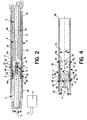
- the drill assembly 1 preferably includes a source of operating fluid A (shown diagrammatically), which is preferably compressed air, a casing 2 having a longitudinal centerline 3 and a piston 6 disposed within the casing 2 such that a piston reservoir chamber 27 is defined generally between the piston 6 and the casing 2.
- the distributor device 10 basically comprises a generally cylindrical body 12 disposeable within the casing 2 and having a central axis 11 and first and second opposing ends 12a, 12b, respectively, spaced apart along the axis 11.
- the body 12 further has at least one fluid passage 14 extending generally between the two ends 12a, 12b and a deflectable retainer portion 16.
- the retainer portion 16 is configured to releasably engage with the casing 2 to retain the cylindrical body 12 at a desired position P in the casing 2 with respect to the centerline 3. It must be noted that the desired position P is indicated by the location of a designated center point C of the body 12 to facilitate description of the present invention and the particular reference center point C has been selected for convenience only.
- the distributor body 12 further has a first and second interior chambers 23, 25, respectively, and a primary port 48 fluidly connecting the first and second chambers 23 and 25.
- the distributor device 10 preferably further comprises a valve 7 disposed within the body 12 and configured to permit fluid flow through the port 48 and to alternatively prevent fluid flow through the port 48.
- the first or "supply" chamber 23 is fluidly connectable with the operating fluid source A and the fluid passage 14 fluidly connects the supply chamber 23 with the reservoir chamber 27 when the body 12 is located at the desired position P.
- the fluid passage 14 enables operating fluid to be channeled to a return chamber 31 (Fig. 2) to cause the piston 6 to linearly displace in an upward, return direction 3b along the centerline 3, as discussed in further detail below.
- the piston 6 preferably has an upper portion 6a disposeable within the second or "drive” interior chamber 25 such that when the valve 7 permits fluid flow through the port 48, operating fluid flows from the first, supply chamber 23 to the second or “drive” chamber 25 to cause the piston 6 to linearly displace within the casing 2 in a downward, drive direction 3a generally along the casing centerline 3.
- the retainer portion 16 is preferably formed as a segmented ring 17 configured to deflect or collapse generally inwardly toward the body central axis 11 and to alternatively expand generally outwardly away from the axis 11.
- the distributor body 12 preferably further includes a generally solid tubular portion 33 and the retainer segmented ring 17 is integrally attached or formed with the tubular portion 33.
- the segmented ring 17 preferably includes a plurality of slotted openings 18 that divide the retainer portion 16 into a plurality of deflectable, cantilever-like locking arms 20.
- Each locking arm 20 has a first, inner end attached to the body tubular portion 33 and a second, outer or free end 24 engageable with the casing 2 to retain the body 12 at the desired position P.
- the locking arms 20 each have a lug 26 that engages with a retainer recess 9 in the casing 2 to removably mount the distributor body 12 within the casing 2, as described more fully below.
- the distributor device 10 is preferably used with a drill assembly 1 that further includes a backhead 4 attached to an upper end 2a of the casing 2 and a bit 5 slidably disposed at least partially within the lower end 2b of the casing 2.
- the piston 6 is slidably disposed within the casing 2 and reciprocates in first and second directions 3a, 3b, respectively, along the centerline 3. More specifically, the piston upper portion/end 6a slides within the drive chamber 25 of the distributor device 10 and the piston lower end 6b repetitively impacts against the upper end 5a of the bit 5.
- a guide post 8 is attached to the backhead 4, extends through and centers the valve 7 within the distributor body 12 and has a lower end 8a that engages inside the piston 6.
- the drill casing 2 preferably further includes an inner circumferential surface 2c and a retainer recess 9 configured to engage with the retainer portion 16 of the distributor body 12.
- the retainer portion 16 is engageable with the casing recess 9 to retain the distributor body 12 at the desired position P and alternatively disengageable from the casing recess 9 to permit the body 12 to be displaceable in a direction along the casing centerline 3.
- the retainer recess 9 is generally annular and extends circumferentially into the casing 2 from the inner surface 2c and is preferably formed as a single, continuous recess circumscribing the drill centerline 3.
- the retainer recess 9 may be formed as a plurality of separate arcuate recess sections (not shown) spaced circumferentially about the drill centerline 3.
- the casing retainer recess 9 preferably includes an upper, lead-in and release surface section 9a that is sloped or angled so as to face generally radially-inwardly toward the drill centerline 3, a lower, generally radially-extending or "radial" stop surface section 9b and a central inner circumferential surface section 9c disposed between the upper and lower surfaces 9a, 9b, respectively.
- the three casing recess surfaces/surface sections 9a, 9b and 9c interact with specific surfaces of the distributor retainer portion 16, as described below.
- the cylindrical body 12 of the distributor device 10 has inner and outer circumferential surfaces 13, 15, respectively, and is preferably shaped so as to have "axial" cross-sections (i.e., cross-sections perpendicular to and spaced along the axis 11) that are substantially circular.
- the body 12 has an outside diameter Do that is generally constant along the axis 11, except at the region of the locking lugs 26.
- the outside diameter Do of the cylindrical distributor body 12 is sized sufficiently smaller or lesser than an inside diameter D I of the casing 2 to enable installation of the distributor device 10 into the casing 2, as described in further detail below.
- the retainer portion 16 is preferably provided by an integral collapsable ring 17 of the body 12 that is located at the body upper end 12a.
- the slotted openings 18 segment or divide the collapseable ring 17 into eight locking arms 20, which are spaced circumferentially about the central axis 11.
- the distributor body 12 is generally centered about the casing centerline 3.
- each slotted opening 18 extends generally axially and inwardly from the first, upper end 12a of the distributor body 12 and enlarges into a fluid port 19.
- Each fluid port 19 fluidly connects a separate outer fluid passage 14 with the upper supply chamber 23, as discussed in further detail below.
- Each locking arm 20 has a first, inner end 22 integrally attached or formed with the solid tubular portion 33 of the cylindrical body 12 and a second, free end 24 located at the body upper end 12a.
- the arms 20 are each "bendable” or configured to bend or deflect at or about the arm first end 22 so as to displace the arm outer end 24 generally toward the body central axis 11 and to alternatively displace the arm outer end 24 generally away from the body axis 11.
- the arm outer end 24 is movable between a first, most distal position with respect to the central axis 11 (e.g., Fig. 2) and a second, most proximal position with respect to the axis 11 (e.g., Fig. 4), for reasons described below.
- each locking arm 20 includes a projection or lug 26 disposed proximal to, preferably spaced inwardly from, the outer, free end 24 of the arm 20 and extending radially outwardly from an outer surface 21 of the arm 20.
- each lug 26 is each configured to releasably engage with, and are preferably disposable within, the retainer recess 9 of the casing 2 to locate and releasably retain the distributor device 10 at a desired axial position with respect to the drill centerline 3.
- each lug 26 includes an outer circumferential surface section 28, a radially-extending or "radial" stop surface section 30 and an angled or sloped release surface section 32. The three lug surfaces/surface sections 28, 30 and 32 interacting with the surfaces 9a, 9b and 9c of the casing recess 9 in the following manner.
- Each lug 26 is generally sized such that when the entire retainer portion 16 is engaged with the casing recess 9, the outer circumferential surface 28 of each lug 26 is generally disposed against the inner circumferential surface 9c of the casing recess 9, the collective effect of which is to substantially center the distributor body 12 about the drill centerline 3.
- the lug stop surfaces 30 are contactable with the recess stop surface 9b to limit axial movement of the distributor body 12 in the first, downward direction 3a along the drill centerline 3.
- Each radially-outwardly facing release surface 32 is contactable with the radially-inwardly facing lead-in/release surface 9a of the casing recess 9 to generally limit axial movement in the second, upward direction 3b along the drill centerline 3, although the backhead 4 primarily limits distributor body movement in the upward direction 3b, preferably through an intermediate elastic member 66.
- an elastic member 66 such as a belleville spring, a compression cone or another appropriate component, is preferably disposed between the backhead 4 and the body 12 and functions both to develop an axial pre-load on the distributor device 10 and to accommodate variations in manufacturing tolerance of the backhead 4 and the body 12. Therefore, during normal operation of the drill assembly 1, the lugs 26 are retained within the recess 9 as the result of contact between the backhead 4 and the body upper end 12a (i.e., through the elastic member 66) and by contact between the respective lower stop surfaces 30, 9c of the lugs 26 and casing recess 9. The retention of the lugs 26 within the casing recess 9 locates and retains the distributor device 10 at the desired position P with respect to the drill centerline 3.
- an elastic member 66 such as a belleville spring, a compression cone or another appropriate component
- the body 12 begins to displace in the second direction 3a such that the lug release surfaces 32 slide against the casing lead-in surface 9a.
- the interaction between the angled surfaces 32 and 9a deflects the locking arms 20 to bend radially-inwardly about the arm inner ends 24 such that the outer, free ends 26 displace generally inwardly toward the axial centerline 3.
- the retainer portion 16 of the distributor device 10 thereby becomes inwardly collapsed to release the lugs 26 from the casing recess 9 to slide along the inner circumferential surface 2c of the casing 2, as depicted in Fig. 4.
- the distributor device 10 is then capable of being linearly displaced or slided along the drill centerline 3 in the second, upward direction 3b until the body 12 is completely extracted or removed from the casing 2.
- the distributor body 12 preferably has a plurality of fluid passages 14, most preferably eight passages 14, spaced circumferentially about the body axis 11 and each configured to fluidly connect the first, supply chamber 23 with the piston reservoir chamber 27 during normal drill operation.
- Each fluid passage 14 is preferably formed as an outer recess 38 extending radially-inwardly into the body 12 from the body outer circumferential surface 15 and generally axially with respect to the central axis 12. Further, each axial recess 38 is generally rectangular-shaped and extends between a separate one of the upper fluid ports 19 and the second end 12b of the body 12.
- each fluid passage 14 is partially bounded by a proximal section of the casing inner circumferential surface 2c.
- the fluid passages 14 may be provided by axially-extending interior holes or passages (not shown) contained or enclosed within the cylindrical distributor body 12.
- four of the preferred eight recesses 38 preferably include a lower fluid "blow" port 40 disposed generally proximal to the second end 12b of the body 12 and fluidly connecting the particular recess 38 with the second, drive chamber 25.
- the blow ports 40 each establish a fluid path from the upper, supply chamber 23, through the associated fluid passage 14, the particular port 40 and the lower, drive chamber 25, into the drill bore passage 29 and out the casing 2, the fluid path functioning to relieve pressure from the drill assembly 1 when the drill 1 is non-operational.
- the two distributor chambers 23 and 25 are each at least partially bounded by the inner circumferential surface 13 of the body 12 and function to appropriately direct or apply the operating fluid used to operate the drill assembly 1, as discussed above and in further detail below.
- the distributor body 12 preferably further includes an annular shoulder 42 extending radially inwardly from the body inner surface 13.
- the annular shoulder 42 preferably extends circumferentially and continuously about the body inner surface 13 so as to circumscribe the central axis 11.
- the shoulder 42 may alternatively be provided by two or more arcuate shoulder segments (not show) spaced circumferentially about the body inner surface 13.
- the shoulder 42 has an inner circumferential surface 46 bounding the primary port 48 and a radially-extending valve seat surface 44 against which the valve 7 is disposeable, as discussed below.
- the valve 7 is preferably formed as a generally cylindrical block 50 with a central axial bore 52, the central bore 52 having an enlarged, counterbore portion 54.
- the valve block 50 includes a radial shoulder portion 56 having a radially-extending, annular contact surface 58 disposeable against the shoulder seat surface 44.
- the valve block 50 also includes a lower, circular cylindrical portion 60 with an outer circumferential surface 62.
- the valve lower portion 60 is disposeable within the distributor port 48 and has an outer diameter (not indicated) that is lesser than the inner diameter (not indicated) of the body shoulder 42.
- an annular fluid passage 64 is formed within the primary port 48 when the valve 7 is assembled in the distributor device 10.
- the annular fluid passage 64 is defined between the shoulder inner surface 46 and the valve outer surface 62 when the valve 7 is slidably disposed on the guide post 8 of the drill assembly 1.
- the valve 7 may be formed without the lower portion 60, such that the valve contact surface 58 extends completely across the lower end of the valve block 50 and the entire port 48 is used to channel or direct fluid flow between the supply and drive chambers 23 and 25, respectively (structure not shown).
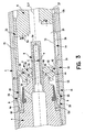
- the valve 7 is displaceable with respect the distributor body 12 between a first position (as shown in Figs. 3 and 4) and a second position (Fig. 7).
- first position the valve shoulder surface 58 is disposed against the valve seat surface 44 of the shoulder 42 to substantially prevent fluid flow through the annular fluid passage 64.
- second position the valve 7 is spaced axially from the shoulder seat surface 44 in the second direction 3a along the drill centerline 3 so as to permit fluid flow through the annular passage 64 within the port 48, and therefore between the supply and drive chambers 23 and 25, respectively.
- valve 7 moves between the first and second positions by action of the movement of the piston 6 in the second, return direction 3b, which compresses operating fluid within the drive chamber 25 such that the compressed fluid forces the valve body 50 to slide upwardly upon the post 8.
- the opening of the valve 7 permits operating fluid in the supply chamber 23 to flow through the passage 64, into the drive chamber 25 and against the upper end/portion 6a of the piston 6, causing the piston 6 to linearly displace within the casing 2 downwardly along the centerline 3 to impact with the bit 5.
- the distributor body 12 of the present invention is machined from a tube of a hot-rolled metallic material, most preferably 4140 steel, and the valve 7 is machined from a bar of a polymeric material, most preferably acetyl.
- the distributor device 10 of the present invention is not limited to being constructed from any particular type of material and/or fabrication method.
- the body 12 and/or valve 7 may be made of iron, ceramic or a polymeric material and/or may be made by any appropriate fabrication method, such as for example, casting or forging.
- the distributor device 10 is assembled into the casing 2 in the following manner.
- the second or lower end 12b of the cylindrical body 12 is inserted into the upper end 2a of the casing 2 and the body 12 is then "pushed" so as to displace along the drill centerline 3 in the first or downward direction 3a.
- the outer circumferential surface 15 of the body 12 slides against the inner circumferential surface 2c of the casing 2 until the locking lugs 26 contact the upper end 2a of the casing 2.
- a radially-inwardly directed force is applied to the distributor retainer portion 16 to cause the locking arms 20 to collapse or bend radially-inwardly toward the drill centerline 3 to a collapsed configuration, as depicted in Fig. 4.
- the locking arms 20 must bend sufficiently to displace the lugs 26 inwardly by an adequate radial distance to enable the lugs 26 to enter the interior of the casing 2 through the casing first end 2a.
- the lug outer surfaces 28 then slide against the casing inner surface 2c, along with the remainder of the body outer surface 15, as the body 12 displaces along the axis 3 until the lugs 26 reach the casing recess 9.
- the lugs 26 then "snap" or displace radially-outwardly into the casing recess 9 (as shown in Fig. 5) by action of elastic material forces stored in each of the bended cantilever-like locking arms 20.
- the body 12 is then displaced an additional, relatively short distance along the centerline 3 in the first direction 3b until the lug radial stop surface 30 contacts the casing radial stop surface 9b, such that the distributor device 10 is positioned or located at the desired position P.
- the elastic member 66 is placed against the first, upper end 12a of the body 12 and then the backhead 4 of the drill assembly 1 is attached or threaded onto the upper end 2a of the casing 2, such that a downwardly-facing radial surface 4a of the backhead 4 compresses the elastic member 66 against the body first end 12a.
- the backhead 4 thereby limits movement of the distributor body 12 in the first or upper direction 3a and thus prevents the lugs 26 from sliding out of the casing recess 9.
- the distributor device 10 is retained at a specific position on or with respect to the drill centerline 3, with the body central axis 11 being substantially collinear with the centerline 3.
- the distributor body 12 remains substantially stationary at the desired position P until it is desired to remove the distributor device 10 from the casing 2, which is accomplished by releasing the lugs 26 from the casing recess 9 as described above.
- the preferred distributor device 10 of the present invention is clearly advantageous compared with previously known distributor devices, such as those discussed in the Background section of this disclosure.
- the distributor body 12 is retained in a specific position in the casing 2 without the need for additional mounting or retaining components, such as a separate retaining ring or ring segments.
- the circumferentially spaced lugs 26 contact the casing recess 9 in a manner such that the forces applied by the retainer portion 16 are evenly distributed, thereby preventing any loading imbalance such as occurs with split-ring type retaining devices, as described above.
- the need for special tools or fixtures generally required to assemble a cylinder and ring assembly is also eliminated.
- the incorporation of the valve 7 into the distributor device 10 eliminates certain valve components required with other fluid distributor systems.
Landscapes
- Engineering & Computer Science (AREA)
- Life Sciences & Earth Sciences (AREA)
- Geology (AREA)
- Mining & Mineral Resources (AREA)
- Mechanical Engineering (AREA)
- Physics & Mathematics (AREA)
- Environmental & Geological Engineering (AREA)
- Fluid Mechanics (AREA)
- General Life Sciences & Earth Sciences (AREA)
- Geochemistry & Mineralogy (AREA)
- Earth Drilling (AREA)
- Percussive Tools And Related Accessories (AREA)
Claims (19)
- Fluidverteileinrichtung (10) für eine Schlagbohranordnung (1), wobei die Bohranordnung ein im Wesentlichen rohrförmiges Gehäuse (2) enthält, das eine Längsmittellinie (3) hat, wobei die Verteileinrichtung enthält:einen im Wesentlichen zylindrischen Körper (12), der innerhalb des Gehäuses anordbar ist und eine Mittelachse (11), zwei sich gegenüberliegende Enden (12a, 12b), die entlang der Achse beabstandet sind, und zumindest einen Fluiddurchlass (14) hat, der sich im Wesentlichen zwischen den zwei Enden erstreckt,dadurch gekennzeichnet, dass der Körper (12) weiter enthält:einen biegsamen Halterungsbereich (16), der gestaltet ist zum lösbaren Eingreifen mit dem Gehäuse (2), so dass der Körper (12) an einer gewünschten Position (P) in Bezug auf die Mittellinie (3) angeordnet wird.
- Verteileinrichtung (10) nach Anspruch 1, wobei:die Bohranordnung (1) weiter eine Einspeisung (A) des Betriebsfluids und einen Kolben (6) enthält, wobei der Kolben innerhalb des Gehäuses (2) angeordnet ist, so dass eine Speicherkammer (27) im Wesentlichen zwischen dem Kolben und dem Gehäuse definiert ist; undder Körper (12) weiter eine innere Zulaufkammer (23) hat, wobei die Zulaufkammer in Fluidverbindung mit der Betriebsfluideinspeisung bringbar ist und der Fluiddurchlass (14) die Zulaufkammer und die Speicherkammer in Fluidverbindung bringt, wenn der Körper an der gewünschten Position (P) angeordnet ist.
- Verteileinrichtung (10) nach Anspruch 1 oder 2, wobei:der Körper (12) weiter eine erste und zweite innere Kammer (23, 25) und einen Anschluss (48) hat, der die erste und zweite Kammer in Fluidverbindung bringt; unddie Verteileinrichtung weiter ein Ventil (7) enthält, das innerhalb des Körpers angeordnet und gestaltet ist zum Erlauben, dass Fluid durch den Anschluss fließt, und wahlweise Verhindern, dass Fluid durch den Anschluss fließt.
- Verteileinrichtung (10) nach Anspruch 1, 2 oder 3, wobei der Halterungsbereich (16) als in Segmente geteilter Ring (17) geformt ist, der gestaltet ist zum im Wesentlichen nach innen in Richtung der Körpermittelachse (11) Zusammenklappen, und wahlweisen Ausdehnen im Wesentlichen weg von der Achse.
- Fluidverteileinrichtung (10) für eine Schlagbohranordnung (1), wobei die Bohranordnung ein im Wesentlichen rohrförmiges Gehäuse (2) enthält, das eine Längsmittellinie (3) hat, wobei die Verteileinrichtung enthält:einen im Wesentlichen zylindrischen Körper (12),dadurch gekennzeichnet, dass der Körper (12) weiter enthält:eine erste und zweite innere Kammer (23, 25), einen Anschluss (48), der die erste und zweite Kammer in Fluidverbindung bringt, und einen biegsamen Halterungsbereich (16), der gestaltet ist zum lösbaren Eingreifen mit dem Gehäuse (2), so dass der Körper (12) an einer gewünschten Position (P) in Bezug auf die Mittellinie des Gehäuses (3) gehalten wird; unddie Verteileinrichtung (10) weiter enthält:ein Ventil (7), das innerhalb des Körpers angeordnet und gestaltet ist zum Erlauben, dass Fluid durch den Anschluss fließt, und wahlweisen Verhindern, dass Fluid durch den Anschluss fließt.
- Verteileinrichtung (10) nach Anspruch 5, wobei der Körper (12) weiter eine Mittelachse (11), zwei sich gegenüberliegende Enden (12a, 12b), die entlang der Achse beabstandet sind, und zumindest einen Fluiddurchlass (14) hat, der sich im Wesentlichen zwischen den zwei Enden erstreckt.
- Verteileinrichtung (10) nach Anspruch 6, wobei:die Bohranordnung (1) weiter einen Kolben (6) enthält, der innerhalb des Gehäuses (2) angeordnet ist, so dass eine Speicherkammer (27) im Wesentlichen zwischen dem Kolben und dem Gehäuse definiert ist; undder Fluiddurchlass (14) die erste Kammer (23) und die Speicherkammer (27) in Fluidverbindung bringt, wenn der Körper an der gewünschten Position (P) angeordnet ist.
- Verteileinrichtung (10) nach einem der Ansprüche 1 bis 4, 6 oder 7, wobei der Körper (12) weiter eine äußere Umfangsoberfläche (15) hat und der Fluiddurchlass (14) als eine Aussparung (38) geformt ist, die sich in den Körper von der äußeren Oberfläche und im Wesentlichen axial in Bezug auf die Mittelachse (11) erstreckt.
- Verteileinrichtung (10) nach Anspruch 8, wobei der Körper (12) eine Mehrzahl von Fluiddurchlassaussparungen (14) hat, die in Umfangsrichtung um die Mittelachse (11) beabstandet sind.
- Verteileinrichtung (10) nach einem der Ansprüche 3 bis 9, wobei:die Bohranordnung (1) weiter einen Kolben (6) und eine Einspeisung (A) des Betriebsfluids enthält, wobei der Kolben innerhalb des Gehäuses (2) angeordnet ist und einen Bereich (6a) hat, der zumindest teilweise innerhalb der zweiten Kammer (25) des Körpers anordbar ist; unddie erste Kammer (23) des Körpers mit der Betriebsfluideinspeisung in Fluidverbindung bringbar ist, so dass, wenn der Kolbenbereich innerhalb der zweiten Kammer des Körpers angeordnet ist und das Ventil (7) das Fluid durch den Anschluss (48) fließen lässt, die Betriebsflüssigkeit von der ersten Kammer in die zweite Kammer fließt zum Bewirken, dass der Kolben linear innerhalb des Gehäuses in eine Richtung (3a) im Wesentlichen entlang der Gehäusemittellinie (11) verstellt wird.
- Verteileinrichtung (10) nach einem der Ansprüche 3 bis 10, wobei:der Körper (12) weiter eine innere Umfangsoberfläche (13) und eine ringförmige Randleiste (42) hat, die sich von der inneren Oberfläche radial nach innen und in Umfangsrichtung um die Mittelachse (11) erstreckt, wobei die Randleiste eine innere Umfangsoberfläche (46), die den Anschluss (48) definiert, und eine radial erstreckende Ventilsitzoberfläche (44) hat; unddas Ventil (7) beweglich zwischen einer ersten Ventilposition, in der das Ventil gegen die Sitzoberfläche angeordnet ist, so dass es verhindert, dass Flüssigkeit durch den Anschluss fließt, und einer zweiten Ventilposition ist, in der das Ventil von der Sitzoberfläche beabstandet ist, so dass es Fluid durch den Anschluss fließen lässt.
- Verteileinrichtung (10) nach Anspruch 11, wobei die Bohranordnung (1) weiter ein Rückteil (4) enthält, das eine Stange (8) hat, wobei die Stange zumindest teilweise innerhalb des Verteilkörpers (12) angeordnet ist, das Ventil (7) auf der Stange anordbar ist, so dass es sich gleitend zwischen der ersten und zweiten Ventilposition verschiebt.
- Verteileinrichtung (10) nach einem der vorhergehenden Ansprüche, wobei:das Gehäuse (2) weiter eine innere Umfangsoberfläche (2c) und eine im Wesentlichen ringförmige Aussparung (9) enthält, die sich in Umfangsrichtung in das Gehäuse von der inneren Oberfläche erstreckt; undder Halterungsbereich (16) mit der Gehäuseaussparung eingreifbar zum Halten des Verteilkörpers (12) an der gewünschten Position (P) und wahlweise lösbar aus der Gehäuseaussparung ist zum Erlauben, dass der Körper in einer Richtung (3a, 3b) entlang der Gehäusemittellinie (11) verstellbar ist.
- Verteileinrichtung (10) nach einem der vorhergehenden Ansprüche, wobei der Körper (12) weiter einen im Wesentlichen festen rohrförmigen Bereich (33) enthält, wobei der Halterungsbereich (16) integral mit dem rohrförmigen Bereich geformt ist und eine Mehrzahl von biegsamen Schließarmen (20) enthält, wobei jeder Schließarm (20) ein inneres Ende (22), das an dem rohrförmigen Bereich befestigt ist, und ein äußeres freies Ende (24) hat, das mit dem Gehäuse (2) zum Halten des Körpers an der gewünschten Position (P) eingreifbar ist.
- Verteileinrichtung (10) nach Anspruch 14, wobei jeder Schließarm (20) im Wesentlichen um das innere Ende (22) des Arms biegbar ist, so dass das äußere Ende (24) des Arms im Wesentlichen in Richtung der Körpermittelachse (11) verstellt wird, und wahlweise das äußere Ende im Wesentlichen weg von der Körpermittelachse verstellt wird.
- Verteileinrichtung (10) nach Anspruch 14 oder 15, wobei die Mehrzahl von Schließarmen (20) in Umfangsrichtung um die Körperachse (11) beabstandet sind, so dass, wenn die Arme mit dem Gehäuse (2) eingreifen, der Verteilkörper (12) im Wesentlichen um die Gehäusemittellinie (3) zentriert ist.
- Verteileinrichtung (10) nach Anspruch 14, 15 oder 16, wobei:das Gehäuse (2) weiter eine innere Umfangsoberfläche (2c) und eine im Wesentlichen ringförmige Aussparung (9) enthält, die sich in Umfangsrichtung in das Gehäuse von der inneren Oberfläche erstreckt; undjeder Schließarm (20) eine Klemme (26) enthält, die proximal zum äußeren Ende (24) des Arms angeordnet ist und innerhalb der Gehäuseaussparung anordbar ist, so dass der Verteilkörper (12) an der gewünschten Position (P) gehalten wird.
- Verteileinrichtung (10) nach Anspruch 17, wobei:die Gehäuseaussparung (9) einen im Wesentlichen radialen Oberflächenteil (9c) und einen winkeligen Oberflächenteil (9a) hat; undjede Klemme (26) einen im Wesentlichen radialen Oberflächenteil (28) enthält, der mit dem radialen Oberflächenteil der Aussparung verbindbar ist, wenn der Verteilkörper (12) in eine erste Richtung (3a) entlang der Gehäusemittellinie (3) verstellt wird, so dass der Körper an der gewünschten Position (P) angeordnet wird, und einen winkeligen Oberflächenteil (32) enthält, der gleitend gegen den winkeligen Oberflächenteil der Aussparung ist, so dass der Arm (20) nach innen in Richtung der Mittelachse (11) gebogen wird, wenn der Körper in eine zweite, gegenläufige Richtung (3b) verstellt wird zum Lösen der Klemme aus der Aussparung, so dass der Körper weiter innerhalb des Gehäuses in die zweite Richtung verstellbar ist.
- Schlagbohranordnung (1) enthaltend:ein Gehäuse (2), das eine Längsmittellinie (3) und eine innere Umfangsoberfläche (2c) hat;einen Kolben (6), der innerhalb des Gehäuses angeordnet ist, so dass eine Kolbenspeicherkammer (27) im Wesentlichen zwischen dem Kolben und der inneren Oberfläche des Gehäuses definiert ist;einen Verteilzylinder (10), der innerhalb des Gehäuses angeordnet ist und eine Mittelachse (11), die im Wesentlichen kolinear zur Gehäusemittellinie ist, zwei sich gegenüberliegende axiale Enden (12, 12b), die entlang der Achse beabstandet sind, und zumindest einen Fluiddurchlass (14) enthält, der sich im Wesentlichen zwischen den zwei Enden (12a, 12b) erstreckt,dadurch gekennzeichnet, dass der Verteilzylinder (10) weiter enthält:eine erste und zweite innere Kammer (23, 25), einen Anschluss (48), der die erste und zweite Kammer in Fluidverbindung bringt, wobei der zumindest eine Fluiddurchlass (14) die erste Kammer mit der Speicherkammer (27) in Fluidverbindung bringt, und einen biegsamen Halterungsbereich (16), der lösbar mit der inneren Oberfläche (2c) des Gehäuses eingreift, so dass der Verteilzylinder (10) in einer gewünschten Position (P) in Bezug auf die Gehäusemittellinie (3) gehalten wird; unddie Schlagbohranordnung (1) weiter enthält:ein Ventil (7), das innerhalb des Verteilzylinders angeordnet und gestaltet ist zum Erlauben, dass Fluid durch den Anschluss fließt und wahlweise Verhindern, dass Fluid durch den Anschluss fließt.
Applications Claiming Priority (3)
| Application Number | Priority Date | Filing Date | Title |
|---|---|---|---|
| US33295401P | 2001-11-14 | 2001-11-14 | |
| US332954P | 2001-11-14 | ||
| PCT/US2002/036768 WO2003042490A1 (en) | 2001-11-14 | 2002-11-14 | Fluid distributor device for down-hole-drills |
Publications (2)
| Publication Number | Publication Date |
|---|---|
| EP1451437A1 EP1451437A1 (de) | 2004-09-01 |
| EP1451437B1 true EP1451437B1 (de) | 2006-08-09 |
Family
ID=23300604
Family Applications (1)
| Application Number | Title | Priority Date | Filing Date |
|---|---|---|---|
| EP02803231A Expired - Lifetime EP1451437B1 (de) | 2001-11-14 | 2002-11-14 | Fluidverteilvorrichtung für bohrer im bohrloch |
Country Status (7)
| Country | Link |
|---|---|
| US (1) | US7159676B2 (de) |
| EP (1) | EP1451437B1 (de) |
| CN (1) | CN100458096C (de) |
| AU (1) | AU2002356955B2 (de) |
| CA (1) | CA2467426C (de) |
| DE (1) | DE60213850T2 (de) |
| WO (1) | WO2003042490A1 (de) |
Families Citing this family (17)
| Publication number | Priority date | Publication date | Assignee | Title |
|---|---|---|---|---|
| IES20020794A2 (en) * | 2002-10-04 | 2003-02-19 | Minroc Techn Promotions Ltd | A down-the-hole hammer |
| US6799641B1 (en) * | 2003-06-20 | 2004-10-05 | Atlas Copco Ab | Percussive drill with adjustable flow control |
| EP1885988B1 (de) * | 2005-04-27 | 2015-09-09 | Atlas Copco Secoroc LLC | Auslassventil und bohreranordnung für bohrloch-schlagbohrmaschinen |
| US7617889B2 (en) * | 2005-11-03 | 2009-11-17 | Rockmore International, Inc. | Backhead and drill assembly with backhead |
| US8800690B2 (en) * | 2008-03-31 | 2014-08-12 | Center Rock Inc. | Down-the-hole drill hammer having a reverse exhaust system and segmented chuck assembly |
| US8302707B2 (en) * | 2009-01-28 | 2012-11-06 | Center Rock Inc. | Down-the-hole drill reverse exhaust system |
| SE539153C2 (sv) * | 2008-03-31 | 2017-04-18 | Center Rock Inc | Drivkoppling för sänkborr |
| USD656974S1 (en) | 2009-01-28 | 2012-04-03 | Center Rock Inc. | Drill bit |
| US8622152B2 (en) | 2009-01-28 | 2014-01-07 | Center Rock Inc. | Down-the-hole drill hammer having a sliding exhaust check valve |
| US7992652B2 (en) * | 2009-02-05 | 2011-08-09 | Atlas Copco Secoroc Llc | Fluid distributor cylinder for percussive drills |
| US8011455B2 (en) | 2009-02-11 | 2011-09-06 | Atlas Copco Secoroc Llc | Down hole hammer having elevated exhaust |
| US8561730B2 (en) * | 2010-03-23 | 2013-10-22 | Atlas Copco Secoroc Llc | Foot valve assembly for a down hole drill |
| SE534794C2 (sv) * | 2010-04-01 | 2011-12-27 | Atlas Copco Rock Drills Ab | Hydraulisk slående anordning, kolvstyrning, samt borrigg |
| US8631884B2 (en) | 2010-06-04 | 2014-01-21 | Center Rock Inc. | Pressure reversing valve assembly for a down-the-hole percussive drilling apparatus |
| EP2739810A2 (de) * | 2011-08-02 | 2014-06-11 | Plumettaz Holding S.A. | Bohrwerkzeug zum verlegen eines rohres im boden |
| HK1155608A2 (en) * | 2012-02-10 | 2012-05-18 | Top Mark Mechanical Equipment Limited | Method and apparatus for controlling the operation of cluster drill of down-the-hole hammers |
| CL2017001018A1 (es) * | 2017-04-25 | 2017-12-15 | Drillco Tools S A | Ensamble de culata en martillo de fondo |
Family Cites Families (6)
| Publication number | Priority date | Publication date | Assignee | Title |
|---|---|---|---|---|
| USRE25705E (en) * | 1961-02-27 | 1964-12-29 | Valving arrangement for rock drills | |
| SU652279A1 (ru) * | 1975-10-01 | 1979-03-15 | Институт Горного Дела Со Ан Ссср | Устройство ударного действи дл образовани скважин в грунте |
| GB8915302D0 (en) * | 1989-07-04 | 1989-08-23 | Andergauge Ltd | Drill string stabiliser |
| US5325926A (en) * | 1993-02-05 | 1994-07-05 | Ingersoll-Rand Company | Reversible casing for a down-the-hole percussive apparatus |
| WO1999064711A2 (en) * | 1998-06-12 | 1999-12-16 | Ingersoll-Rand Company | Improved backhead and check valve for down-hole drills |
| AUPP426398A0 (en) * | 1998-06-22 | 1998-07-16 | Azuko Pty Ltd | A component mounting method and apparatus for a percussion tool |
-
2002
- 2002-11-14 AU AU2002356955A patent/AU2002356955B2/en not_active Ceased
- 2002-11-14 WO PCT/US2002/036768 patent/WO2003042490A1/en not_active Ceased
- 2002-11-14 CA CA002467426A patent/CA2467426C/en not_active Expired - Fee Related
- 2002-11-14 US US10/495,499 patent/US7159676B2/en not_active Expired - Fee Related
- 2002-11-14 DE DE60213850T patent/DE60213850T2/de not_active Expired - Lifetime
- 2002-11-14 CN CNB028270045A patent/CN100458096C/zh not_active Expired - Fee Related
- 2002-11-14 EP EP02803231A patent/EP1451437B1/de not_active Expired - Lifetime
Also Published As
| Publication number | Publication date |
|---|---|
| CN100458096C (zh) | 2009-02-04 |
| CA2467426A1 (en) | 2003-05-22 |
| DE60213850D1 (de) | 2006-09-21 |
| US20050034899A1 (en) | 2005-02-17 |
| CA2467426C (en) | 2009-12-15 |
| CN1612973A (zh) | 2005-05-04 |
| DE60213850T2 (de) | 2007-10-04 |
| AU2002356955B2 (en) | 2008-07-17 |
| WO2003042490A1 (en) | 2003-05-22 |
| EP1451437A1 (de) | 2004-09-01 |
| US7159676B2 (en) | 2007-01-09 |
Similar Documents
| Publication | Publication Date | Title |
|---|---|---|
| EP1451437B1 (de) | Fluidverteilvorrichtung für bohrer im bohrloch | |
| AU2002356955A1 (en) | Fluid distributor device for down-hole-drills | |
| US6510904B1 (en) | Protected tool bushing for an impact hammer | |
| KR100754815B1 (ko) | 다운홀 드릴용 신속 분리 드릴 비트 | |
| US6237704B1 (en) | Backhead and check valve for down-hole drills | |
| WO2014150521A1 (en) | Hydraulic hammer having impact system subassembly | |
| KR20020059349A (ko) | 로봇 핸드용 툴 연결장치 | |
| EP1641997B1 (de) | Bohrhammer mit einstellbarer durchflussregelung | |
| EP3258117A1 (de) | Flüssigkeitsdruckzylinder | |
| JPH08506866A (ja) | ダウンザホール衝撃装置用可逆ケーシング | |
| US20080078584A1 (en) | Bit assembly for down-hole drills | |
| EP0584330B1 (de) | Umkehrbares meissellager für bohrhammer | |
| US20040084224A1 (en) | Bore hole opener | |
| EP0011218B1 (de) | Abdichtung und Rückhaltung von teleskopisch verbundenen Elementen | |
| US5992537A (en) | Back end connection in a downhole drill | |
| EP0774041A1 (de) | Verriegelung einer probenröhre in einem bohrlochmotor | |
| WO2017013597A1 (en) | A pneumatic drill hammer | |
| CN118653775B (zh) | 差动型风动潜孔锤 | |
| CN116438399B (zh) | 具有反向止回的先导式旁通阀 | |
| WO2006008723A2 (en) | A down-the-hole hammer | |
| CN118774576A (zh) | 气动潜孔锤 | |
| CA2155506C (en) | Reversible casing for a down-the-hole percussive apparatus | |
| WO2025029659A1 (en) | Down-the-hole hammer having an inverted casing | |
| CN121245688A (zh) | 一种工装夹具和修刀仪 |
Legal Events
| Date | Code | Title | Description |
|---|---|---|---|
| PUAI | Public reference made under article 153(3) epc to a published international application that has entered the european phase |
Free format text: ORIGINAL CODE: 0009012 |
|
| 17P | Request for examination filed |
Effective date: 20040603 |
|
| AK | Designated contracting states |
Kind code of ref document: A1 Designated state(s): AT BE BG CH CY CZ DE DK EE ES FI FR GB GR IE IT LI LU MC NL PT SE SK TR |
|
| AX | Request for extension of the european patent |
Extension state: AL LT LV MK RO SI |
|
| GRAP | Despatch of communication of intention to grant a patent |
Free format text: ORIGINAL CODE: EPIDOSNIGR1 |
|
| GRAS | Grant fee paid |
Free format text: ORIGINAL CODE: EPIDOSNIGR3 |
|
| GRAA | (expected) grant |
Free format text: ORIGINAL CODE: 0009210 |
|
| AK | Designated contracting states |
Kind code of ref document: B1 Designated state(s): DE GB SE |
|
| REG | Reference to a national code |
Ref country code: GB Ref legal event code: FG4D |
|
| REF | Corresponds to: |
Ref document number: 60213850 Country of ref document: DE Date of ref document: 20060921 Kind code of ref document: P |
|
| REG | Reference to a national code |
Ref country code: SE Ref legal event code: TRGR |
|
| PLBE | No opposition filed within time limit |
Free format text: ORIGINAL CODE: 0009261 |
|
| STAA | Information on the status of an ep patent application or granted ep patent |
Free format text: STATUS: NO OPPOSITION FILED WITHIN TIME LIMIT |
|
| 26N | No opposition filed |
Effective date: 20070510 |
|
| REG | Reference to a national code |
Ref country code: DE Ref legal event code: R082 Ref document number: 60213850 Country of ref document: DE Representative=s name: KRAMER - BARSKE - SCHMIDTCHEN, DE |
|
| REG | Reference to a national code |
Ref country code: GB Ref legal event code: 732E Free format text: REGISTERED BETWEEN 20131107 AND 20131113 |
|
| REG | Reference to a national code |
Ref country code: DE Ref legal event code: R081 Ref document number: 60213850 Country of ref document: DE Owner name: LYON, LELAND, H., US Free format text: FORMER OWNER: INGERSOLL-RAND CO.,LELAND, H. LYON, , US Effective date: 20131119 Ref country code: DE Ref legal event code: R081 Ref document number: 60213850 Country of ref document: DE Owner name: ATLAS COPCO SECOROC LLC, US Free format text: FORMER OWNER: INGERSOLL-RAND CO.,LELAND, H. LYON, , US Effective date: 20131119 Ref country code: DE Ref legal event code: R082 Ref document number: 60213850 Country of ref document: DE Representative=s name: KRAMER - BARSKE - SCHMIDTCHEN, DE Effective date: 20131119 Ref country code: DE Ref legal event code: R082 Ref document number: 60213850 Country of ref document: DE Representative=s name: KRAMER BARSKE SCHMIDTCHEN PATENTANWAELTE PARTG, DE Effective date: 20131119 Ref country code: DE Ref legal event code: R081 Ref document number: 60213850 Country of ref document: DE Owner name: LYON, LELAND, H., ROANOKE, US Free format text: FORMER OWNER: INGERSOLL-RAND CO.,LELAND, H. LYON, , US Effective date: 20131119 Ref country code: DE Ref legal event code: R081 Ref document number: 60213850 Country of ref document: DE Owner name: ATLAS COPCO SECOROC LLC, GRAND PRAIRIE, US Free format text: FORMER OWNER: INGERSOLL-RAND CO.,LELAND, H. LYON, , US Effective date: 20131119 Ref country code: DE Ref legal event code: R081 Ref document number: 60213850 Country of ref document: DE Owner name: ATLAS COPCO SECOROC LLC, GRAND PRAIRIE, US Free format text: FORMER OWNERS: INGERSOLL-RAND CO., WOODCLIFF LAKE, N.J., US; LYON, LELAND, H., ROANOKE, VA., US Effective date: 20131119 Ref country code: DE Ref legal event code: R081 Ref document number: 60213850 Country of ref document: DE Owner name: LYON, LELAND, H., ROANOKE, US Free format text: FORMER OWNERS: INGERSOLL-RAND CO., WOODCLIFF LAKE, N.J., US; LYON, LELAND, H., ROANOKE, VA., US Effective date: 20131119 |
|
| PGFP | Annual fee paid to national office [announced via postgrant information from national office to epo] |
Ref country code: DE Payment date: 20131127 Year of fee payment: 12 Ref country code: SE Payment date: 20131127 Year of fee payment: 12 Ref country code: GB Payment date: 20131127 Year of fee payment: 12 |
|
| REG | Reference to a national code |
Ref country code: DE Ref legal event code: R119 Ref document number: 60213850 Country of ref document: DE |
|
| REG | Reference to a national code |
Ref country code: SE Ref legal event code: EUG |
|
| GBPC | Gb: european patent ceased through non-payment of renewal fee |
Effective date: 20141114 |
|
| PG25 | Lapsed in a contracting state [announced via postgrant information from national office to epo] |
Ref country code: SE Free format text: LAPSE BECAUSE OF NON-PAYMENT OF DUE FEES Effective date: 20141115 |
|
| PG25 | Lapsed in a contracting state [announced via postgrant information from national office to epo] |
Ref country code: GB Free format text: LAPSE BECAUSE OF NON-PAYMENT OF DUE FEES Effective date: 20141114 Ref country code: DE Free format text: LAPSE BECAUSE OF NON-PAYMENT OF DUE FEES Effective date: 20150602 |