EP1451623B1 - Dichtungssystem für optische stecker - Google Patents
Dichtungssystem für optische stecker Download PDFInfo
- Publication number
- EP1451623B1 EP1451623B1 EP02783298A EP02783298A EP1451623B1 EP 1451623 B1 EP1451623 B1 EP 1451623B1 EP 02783298 A EP02783298 A EP 02783298A EP 02783298 A EP02783298 A EP 02783298A EP 1451623 B1 EP1451623 B1 EP 1451623B1
- Authority
- EP
- European Patent Office
- Prior art keywords
- connector according
- ball valve
- connector
- male
- female
- Prior art date
- Legal status (The legal status is an assumption and is not a legal conclusion. Google has not performed a legal analysis and makes no representation as to the accuracy of the status listed.)
- Expired - Lifetime
Links
- 238000007789 sealing Methods 0.000 title claims abstract description 26
- 230000003287 optical effect Effects 0.000 title claims description 15
- 239000000835 fiber Substances 0.000 claims description 18
- 239000000919 ceramic Substances 0.000 claims description 4
- 239000012530 fluid Substances 0.000 claims description 4
- 239000013307 optical fiber Substances 0.000 claims description 4
- 230000009471 action Effects 0.000 claims description 2
- 239000011248 coating agent Substances 0.000 claims description 2
- 238000000576 coating method Methods 0.000 claims description 2
- 238000006073 displacement reaction Methods 0.000 claims description 2
- 229920001971 elastomer Polymers 0.000 claims description 2
- 239000000463 material Substances 0.000 claims description 2
- 230000013011 mating Effects 0.000 claims description 2
- 229910052751 metal Inorganic materials 0.000 claims description 2
- 239000002184 metal Substances 0.000 claims description 2
- 229920001187 thermosetting polymer Polymers 0.000 claims description 2
- 238000011010 flushing procedure Methods 0.000 claims 1
- 238000003780 insertion Methods 0.000 description 7
- 230000037431 insertion Effects 0.000 description 7
- XLYOFNOQVPJJNP-UHFFFAOYSA-N water Substances O XLYOFNOQVPJJNP-UHFFFAOYSA-N 0.000 description 5
- 238000004891 communication Methods 0.000 description 4
- 238000000034 method Methods 0.000 description 4
- 230000008569 process Effects 0.000 description 4
- 239000000356 contaminant Substances 0.000 description 3
- 238000011109 contamination Methods 0.000 description 3
- 230000007246 mechanism Effects 0.000 description 3
- 239000004576 sand Substances 0.000 description 3
- 239000007787 solid Substances 0.000 description 3
- 230000006866 deterioration Effects 0.000 description 2
- 238000005461 lubrication Methods 0.000 description 2
- 239000002245 particle Substances 0.000 description 2
- 239000013535 sea water Substances 0.000 description 2
- 229920006169 Perfluoroelastomer Polymers 0.000 description 1
- RTAQQCXQSZGOHL-UHFFFAOYSA-N Titanium Chemical compound [Ti] RTAQQCXQSZGOHL-UHFFFAOYSA-N 0.000 description 1
- NRTOMJZYCJJWKI-UHFFFAOYSA-N Titanium nitride Chemical compound [Ti]#N NRTOMJZYCJJWKI-UHFFFAOYSA-N 0.000 description 1
- 230000004888 barrier function Effects 0.000 description 1
- 238000005260 corrosion Methods 0.000 description 1
- 230000007797 corrosion Effects 0.000 description 1
- 230000008878 coupling Effects 0.000 description 1
- 238000010168 coupling process Methods 0.000 description 1
- 238000005859 coupling reaction Methods 0.000 description 1
- 238000005553 drilling Methods 0.000 description 1
- 230000008030 elimination Effects 0.000 description 1
- 238000003379 elimination reaction Methods 0.000 description 1
- 230000002452 interceptive effect Effects 0.000 description 1
- 230000014759 maintenance of location Effects 0.000 description 1
- 239000003129 oil well Substances 0.000 description 1
- -1 polytetrafluoroethylene Polymers 0.000 description 1
- 229920001343 polytetrafluoroethylene Polymers 0.000 description 1
- 239000004810 polytetrafluoroethylene Substances 0.000 description 1
- 238000005096 rolling process Methods 0.000 description 1
- 239000010936 titanium Substances 0.000 description 1
- 229910052719 titanium Inorganic materials 0.000 description 1
Images






Classifications
-
- G—PHYSICS
- G02—OPTICS
- G02B—OPTICAL ELEMENTS, SYSTEMS OR APPARATUS
- G02B6/00—Light guides; Structural details of arrangements comprising light guides and other optical elements, e.g. couplings
- G02B6/24—Coupling light guides
- G02B6/36—Mechanical coupling means
- G02B6/38—Mechanical coupling means having fibre to fibre mating means
- G02B6/3807—Dismountable connectors, i.e. comprising plugs
- G02B6/381—Dismountable connectors, i.e. comprising plugs of the ferrule type, e.g. fibre ends embedded in ferrules, connecting a pair of fibres
- G02B6/3816—Dismountable connectors, i.e. comprising plugs of the ferrule type, e.g. fibre ends embedded in ferrules, connecting a pair of fibres for use under water, high pressure connectors
-
- G—PHYSICS
- G02—OPTICS
- G02B—OPTICAL ELEMENTS, SYSTEMS OR APPARATUS
- G02B6/00—Light guides; Structural details of arrangements comprising light guides and other optical elements, e.g. couplings
- G02B6/24—Coupling light guides
- G02B6/36—Mechanical coupling means
- G02B6/38—Mechanical coupling means having fibre to fibre mating means
- G02B6/3807—Dismountable connectors, i.e. comprising plugs
- G02B6/3833—Details of mounting fibres in ferrules; Assembly methods; Manufacture
- G02B6/3847—Details of mounting fibres in ferrules; Assembly methods; Manufacture with means preventing fibre end damage, e.g. recessed fibre surfaces
- G02B6/3849—Details of mounting fibres in ferrules; Assembly methods; Manufacture with means preventing fibre end damage, e.g. recessed fibre surfaces using mechanical protective elements, e.g. caps, hoods, sealing membranes
Definitions
- the system may be for optical fibres but could equally be considered for hydraulic or electrical applications.
- the valve control system may comprise actuation links, one end of each of which is attached directly to the ball valve, and the other end of which is connected to a rotating cam by means of a roller.
- a second biassing means may be provided to bias the valve control system such that the ball valve is urged toward a closed position.
- the shuttle assembly may be filled with oil to enhance movement of the components and the fibre optic wand through lubrication, to exclude debris and to prevent deterioration of the internal components.
- This fluid may be optically matched to the optical characteristics of the connector, thus minimising any loss in optical performance of the connector in operation.
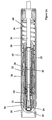
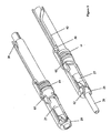
- the connector of the present invention comprises two primary elements, the first of which is illustrated in Figure 1A.
- This female element 1 comprises a fibre optic wand 2 with a solid alignment sleeve 4 .
- the main structure of the female element 1 is provided by a housing unit 5 which encloses a shuttle assembly pin (or actuation sleeve) 6.
- An enveloping sleeve 3 surrounds the shuttle pin 6 and controls its stroke length.
- the end of the shuttle pin 6 is sealed by a ball valve 7 with radial seal 52.
- a spring 8 is provided to bias an actuation cam 9 and rods 40, 41 and rollers 53, 54 toward the ball valve 7.
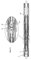
- ball valve 25 and seal 62 is rotated about its central axis by pin 30 engaging with slot 42 of the driver mechanism and moving the link members 27, 27' with rolling pins 63, 73, by rotating cam 66 to provide a clear passageway, through which the fibre optic wand 26 passes through upon connection.
- a spring 61 provides the sealing force for ball valve 25.
- the plug (female) connector's central sealing profile is configured as a internal cone profile to intimately match that of the receptacle, to ensure minimum retention of water and debris.
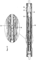
- Figure 3C illustrates the next stage of engagement where the shuttle pin 24 of the male component is forced back into the housing 20 and the sealing shuttle assembly is urged back against spring 60 ejecting any sea water through vent ports 34.
- This relative motion between the shuttle pin 24 and the male fibre optic wand 26 opens the ball valve 25 as described earlier such that the male wand 26 protrudes through into the female component 1.
- any small amounts of trapped water are flushed through the alignment sleeve vent ports 65 as the male wand 26 moves through the ball valves 7, 25 and into the alignment sleeve 4 by displacing oil 18.
Landscapes
- Physics & Mathematics (AREA)
- General Physics & Mathematics (AREA)
- Optics & Photonics (AREA)
- Mechanical Coupling Of Light Guides (AREA)
- Optical Couplings Of Light Guides (AREA)
- Seal Device For Vehicle (AREA)
Claims (16)
- Unterwasserverbinder mit einem Dichtungssystem, wobei das Dichtungssystem umfasst:- eine Streckereinheit;- eine Kupplungseinheit (1),- eine Betätigungshülse (6, 24), die ein Kugelventil (7, 25) in einem freiliegenden Ende der Hülse zurückhält, wobei das Kugelventil eine Dichtungsfunktion bereitstellt, wenn sie sich bei Gebrauch in einer geschlossenen Position befindet;- ein Ventil-Steuersystem, das so angeordnet ist, dass es das Kugelventil mit einem Betätigungselement verbindet und bei Gebrauch das Kugelventil in eine offene Position bei Eingriff der Stecker- und Kopplungseinheiten dreht;- eine Vorspannungseinrichtung (12), die so eingerichtet ist, dass sie das Ventil-Steuersystem vorspannt, um das Kugelventil zur geschlossenen Position zu drücken,gekennzeichnet durch:eine zusätzliche Vorspannungseinrichtung (8), die so angeordnet ist, dass sie die Dichtungskraft steuert, die durch das Kugelventil unabhängig vom Ventil-Steuersystem bereitgestellt wird.
- Verbinder nach Anspruch 1, wobei die verbindet ein Lichtwellenleiter-Steckverbinder ist.
- Verbinder nach Anspruch 1 oder Anspruch 2, wobei das Ventil-Steuersystem Betätigungsgestänge (40, 41) umfasst, wobei von jedem von ihnen das eine Ende direkt am Kugelventil angebracht ist und von jedem von ihnen das andere Ende mit einem Nocken bzw. Mitnehmer (9) verbunden ist, wobei der Mitnehmer so angeordnet ist, dass er sich bei Gebrauch bei Betätigung des Verbinders dreht, um eine relative Befähigung im Betätigungsgestänge zu erzeugen und dadurch das Kugelventil zu drehen.
- Verbinder nach Anspruch 3, wobei das Ventil-Steuersystem des Weiteren einen Stifts (50) und einen Schlitz (51) umfasst, die in Eingriff kommen, um den Mitnehmer (9) bei Eingriff der Stecker- und Kopplungseinheiten (1) bei Gebrauch zu drehen.
- Verbinder nach einem der Ansprüche 2 bis 4, wobei wenigstens eine, die Stecker- oder die Kupplungseinheit umfasst:- einen Lichtwellenleiter-Lesestift in einer Pendelanordnung, wobei die Pendelanordnung eine Betätigungshülse (6, 24) umfasst und sich in einer Gehäuseeinheit (5, 20) befindet.
- Verbinder nach Anspruch 5, des Weiteren mit einem Membransystem (16) zwischen der Gehäuseeinheit und der Pendelanordnung.
- Verbinder nach Anspruch 6, wobei das Membransystem (16) aus einem wärmehärtbaren Kautschuk oder einem Metallbalg hergestellt ist, um eine Wärmeausdehnung und Verschiebung der Betätigungshülse zu ermöglichen.
- Verbinder nach einem der Ansprüche 5 bis 7, wobei die Gehäuseeinheit Ausgieichsbohrungen (34) umfasst, die angeordnet sind, um Restpartikel bzw. Verunreinigungen vom optischen Verbinder während des Eingriffs zu beseitigen.
- Verbinder nach einem der Ansprüche 5 bis 8, wobei das Kugelventil (7, 25) entweder aus Keramik oder Metall ist.
- Verbinder nach einem der Ansprüche 5 bis 9, wobei das Kugelventil (7, 25) mit einem reibungsarmen Überzug beschichtet ist.
- Verbinder nach einem der Ansprüche 5 bis 10, wobei die Pendelanordnung mit einem Öl gefüllt ist, dass optisch an den Lichtwellenleiter-Lesestift angepasst ist.
- Verbinder nach einem der Ansprüche 5 bis 11, wobei Lichtwellenleiter des Lichtwellenleiter-Lesestifts durch hermetisch versiegelte, optisch durchsichtige Fenster geschützt sind.
- Verbinder nach einem der Ansprüche 5 bis 12, wobei der Lichtwellenleiter-Lesestift beim Verbinden anstößt und wenigstens eine der übereinstimmenden Stecker- oder Kopplungseinheiten (1) eine Vorspannungseinrichtung hat, um für ein Aufstapeln von Toleranzen und das Anstoßen in der Gehäuseeinheit (5, 20) zu sorgen.
- Verbinder nach einem der Ansprüche 5 bis 13, wobei der Lichtwellenleiter-Lesestift in einer Ausrichtungshülse (4) in Eingriff kommt.
- Verbinder nach Anspruch 14, wobei die Ausrichtungshülse (4) FluidÖffnungen darin hat.
- Verbinder nach einem der Ansprüche 5 bis 15, der so angeordnet ist, dass er während des Eingriffs eine Spülwirkung erzeugt.
Priority Applications (1)
| Application Number | Priority Date | Filing Date | Title |
|---|---|---|---|
| EP02783298A EP1451623B1 (de) | 2001-12-06 | 2002-12-06 | Dichtungssystem für optische stecker |
Applications Claiming Priority (4)
| Application Number | Priority Date | Filing Date | Title |
|---|---|---|---|
| EP01310203 | 2001-12-06 | ||
| EP01310203 | 2001-12-06 | ||
| EP02783298A EP1451623B1 (de) | 2001-12-06 | 2002-12-06 | Dichtungssystem für optische stecker |
| PCT/GB2002/005540 WO2003048827A2 (en) | 2001-12-06 | 2002-12-06 | Sealing system for optical connector |
Publications (2)
| Publication Number | Publication Date |
|---|---|
| EP1451623A2 EP1451623A2 (de) | 2004-09-01 |
| EP1451623B1 true EP1451623B1 (de) | 2006-09-06 |
Family
ID=8182519
Family Applications (1)
| Application Number | Title | Priority Date | Filing Date |
|---|---|---|---|
| EP02783298A Expired - Lifetime EP1451623B1 (de) | 2001-12-06 | 2002-12-06 | Dichtungssystem für optische stecker |
Country Status (6)
| Country | Link |
|---|---|
| US (1) | US7004638B2 (de) |
| EP (1) | EP1451623B1 (de) |
| AT (1) | ATE338957T1 (de) |
| AU (1) | AU2002347364A1 (de) |
| DE (1) | DE60214589D1 (de) |
| WO (1) | WO2003048827A2 (de) |
Families Citing this family (22)
| Publication number | Priority date | Publication date | Assignee | Title |
|---|---|---|---|---|
| GB0320558D0 (en) * | 2003-09-02 | 2003-10-01 | Diamould Ltd | Hydraulic connector |
| DE102004059258B4 (de) | 2004-12-09 | 2006-09-07 | Gisma Steckverbinder Gmbh | Lichtwellenleiter-Steckverbinder |
| US8436743B2 (en) * | 2007-05-04 | 2013-05-07 | Schlumberger Technology Corporation | Method and apparatus for measuring a parameter within the well with a plug |
| US8192089B2 (en) † | 2007-09-24 | 2012-06-05 | Teledyne Instruments, Inc. | Wet mate connector |
| US8226303B2 (en) | 2009-11-30 | 2012-07-24 | Toth John R | Global link connector system |
| GB201007841D0 (en) * | 2010-05-11 | 2010-06-23 | Rms Ltd | Underwater electrical connector |
| US8944082B2 (en) | 2010-11-22 | 2015-02-03 | Teledyne Instruments, Inc. | Dual reservoir coupler |
| US9057864B2 (en) * | 2013-08-02 | 2015-06-16 | Teledyne Instruments, Inc. | Harsh environment connector with seal closure assisting device |
| WO2015089440A1 (en) * | 2013-12-12 | 2015-06-18 | Teledyne Instruments, Inc. | Subsea optical connector using multiple seals |
| NO2704553T3 (de) * | 2014-03-27 | 2018-02-03 | ||
| US9270051B1 (en) * | 2014-09-04 | 2016-02-23 | Ametek Scp, Inc. | Wet mate connector |
| AU2015394337B2 (en) | 2015-05-14 | 2018-10-25 | Halliburton Energy Services, Inc. | Ball and seat valve for high temperature and pressure applications |
| CN105487180B (zh) * | 2016-01-13 | 2017-03-29 | 中国电子科技集团公司第八研究所 | 一种零浮力光缆水密承力连接器 |
| CA3009529C (en) | 2016-03-17 | 2018-12-11 | Ormond Energy Innovations Inc. | Protective fiber optic termination, system, and method of using same |
| US11404815B2 (en) | 2017-10-30 | 2022-08-02 | Ormond Energy Innovations Inc. | Sealed connector with triggered mating and method of using same |
| WO2019143658A1 (en) | 2018-01-16 | 2019-07-25 | Pontus Subsea Connectors Llc | Device for sealably connecting circuits in contaminated environments and methods of using and making same |
| TWI727144B (zh) * | 2018-02-14 | 2021-05-11 | 普泰光電股份有限公司 | 具有防水功能的光纖連接器 |
| US11217909B2 (en) * | 2019-09-16 | 2022-01-04 | Teledyne Instruments, Inc. | Connector suitable for harsh environments |
| GB2590452A (en) | 2019-12-18 | 2021-06-30 | Siemens Ag | Connector assembly |
| EP4305476A4 (de) | 2021-03-09 | 2025-01-08 | OneSubsea IP UK Limited | Faseroptisches nassverbindungs-verbindersystem |
| US11435536B1 (en) * | 2021-07-29 | 2022-09-06 | Teledyne Instruments, Inc. | Latched optical feedthrough system for subsea wellhead penetration using spherical seals |
| CN119535685B (zh) * | 2024-05-27 | 2025-12-19 | 宁波东方电缆股份有限公司 | 一种水下湿插拔 |
Family Cites Families (13)
| Publication number | Priority date | Publication date | Assignee | Title |
|---|---|---|---|---|
| US3533430A (en) * | 1969-01-01 | 1970-01-01 | Otis Eng Corp | Shuttle valve |
| US3856085A (en) * | 1973-11-15 | 1974-12-24 | Halliburton Co | Improved annulus pressure operated well testing apparatus and its method of operation |
| US4059153A (en) * | 1975-07-14 | 1977-11-22 | Halliburton Company | Weight and pressure operated well testing apparatus and its method of operation |
| US4220176A (en) * | 1978-04-10 | 1980-09-02 | Russell Larry R | Methods and apparatus for controlling fluid flow |
| US4619325A (en) * | 1985-01-29 | 1986-10-28 | Halliburton Company | Well surging method and system |
| FR2682487A1 (fr) | 1991-10-14 | 1993-04-16 | Eca | Connecteur optique, notamment sous-marin. |
| US5738535A (en) * | 1996-03-07 | 1998-04-14 | Ocean Design, Inc. | Underwater connector |
| US6017227A (en) * | 1996-03-07 | 2000-01-25 | Ocean Design, Inc. | Underwater connector |
| NO307436B1 (no) | 1997-10-06 | 2000-04-03 | Optoplan As | Anordning for beskyttelse av fiberoptiske kontakter |
| US5937123A (en) * | 1998-04-22 | 1999-08-10 | Eastman Kodak Company | Fiber optical laser collimating device |
| US5931132A (en) * | 1998-08-24 | 1999-08-03 | Freeland; Mark | Hydraulic lash adjuster with pressure relief check valve |
| US6439778B1 (en) * | 2001-01-17 | 2002-08-27 | Ocean Design, Inc. | Optical fiber connector assembly |
| US6402539B1 (en) * | 2001-10-16 | 2002-06-11 | Ocean Design, Inc. | Self-contained underwater cable branching apparatus and method |
-
2002
- 2002-12-06 EP EP02783298A patent/EP1451623B1/de not_active Expired - Lifetime
- 2002-12-06 AT AT02783298T patent/ATE338957T1/de not_active IP Right Cessation
- 2002-12-06 WO PCT/GB2002/005540 patent/WO2003048827A2/en not_active Ceased
- 2002-12-06 US US10/495,248 patent/US7004638B2/en not_active Expired - Lifetime
- 2002-12-06 DE DE60214589T patent/DE60214589D1/de not_active Expired - Lifetime
- 2002-12-06 AU AU2002347364A patent/AU2002347364A1/en not_active Abandoned
Also Published As
| Publication number | Publication date |
|---|---|
| EP1451623A2 (de) | 2004-09-01 |
| ATE338957T1 (de) | 2006-09-15 |
| AU2002347364A1 (en) | 2003-06-17 |
| US20050002617A1 (en) | 2005-01-06 |
| WO2003048827A2 (en) | 2003-06-12 |
| AU2002347364A8 (en) | 2003-06-17 |
| US7004638B2 (en) | 2006-02-28 |
| DE60214589D1 (de) | 2006-10-19 |
| WO2003048827A3 (en) | 2004-04-29 |
Similar Documents
| Publication | Publication Date | Title |
|---|---|---|
| EP1451623B1 (de) | Dichtungssystem für optische stecker | |
| US4834139A (en) | Radial seal hydraulic coupler | |
| US5810048A (en) | Metal face sealing coupling | |
| US4768538A (en) | Radial seal hydraulic coupler | |
| US8025506B2 (en) | Harsh environment rotary joint electrical connector | |
| US6332787B1 (en) | Wet-mateable electro-optical connector | |
| US7618198B2 (en) | Harsh environment connector | |
| GB2366673A (en) | Wet-mateable electrical connector with metal to metal seal | |
| EP3704765B1 (de) | Abgedichteter verbinder mit getriggertem gegenstecker und verfahren zu seiner verwendung | |
| EP1222484A2 (de) | In nasser umgebung koppelbarer stecker | |
| US7097515B2 (en) | Subsea electrical connector | |
| AU2019363012B2 (en) | Misalignment accommodating hydraulic coupler | |
| US7344316B2 (en) | Connector | |
| EP3735603B1 (de) | Vorrichtung zum abgedichteten verbinden von schaltungen in kontaminierten umgebungen und verfahren zu deren verwendung und herstellung | |
| US8827570B2 (en) | Submarine optical connector | |
| US10439319B2 (en) | Connector part of a subsea connector | |
| CN117590524A (zh) | 一种水下湿插拔连接器的光纤信号连接结构及其使用方法 | |
| EP1657576B1 (de) | Bohrlochkopf mit Unterwasserstecker | |
| EP0183357A2 (de) | Optischer Stecker | |
| GB2318397A (en) | Two part connector | |
| US12287517B2 (en) | Fibre optic wet mate connector system | |
| EP0472652B1 (de) | Verbesserte lösbare schnellkupplung | |
| US20070020965A1 (en) | Hydraulic connector | |
| GB2342461A (en) | Submersible connector | |
| WO2021122063A1 (en) | Connector assembly |
Legal Events
| Date | Code | Title | Description |
|---|---|---|---|
| PUAI | Public reference made under article 153(3) epc to a published international application that has entered the european phase |
Free format text: ORIGINAL CODE: 0009012 |
|
| 17P | Request for examination filed |
Effective date: 20040622 |
|
| AK | Designated contracting states |
Kind code of ref document: A2 Designated state(s): AT BE BG CH CY CZ DE DK EE ES FI FR GB GR IE IT LI LU MC NL PT SE SI SK TR |
|
| AX | Request for extension of the european patent |
Extension state: AL LT LV MK RO |
|
| 17Q | First examination report despatched |
Effective date: 20050422 |
|
| GRAP | Despatch of communication of intention to grant a patent |
Free format text: ORIGINAL CODE: EPIDOSNIGR1 |
|
| GRAS | Grant fee paid |
Free format text: ORIGINAL CODE: EPIDOSNIGR3 |
|
| GRAA | (expected) grant |
Free format text: ORIGINAL CODE: 0009210 |
|
| AK | Designated contracting states |
Kind code of ref document: B1 Designated state(s): AT BE BG CH CY CZ DE DK EE ES FI FR GB GR IE IT LI LU MC NL PT SE SI SK TR |
|
| PG25 | Lapsed in a contracting state [announced via postgrant information from national office to epo] |
Ref country code: IT Free format text: LAPSE BECAUSE OF FAILURE TO SUBMIT A TRANSLATION OF THE DESCRIPTION OR TO PAY THE FEE WITHIN THE PRESCRIBED TIME-LIMIT;WARNING: LAPSES OF ITALIAN PATENTS WITH EFFECTIVE DATE BEFORE 2007 MAY HAVE OCCURRED AT ANY TIME BEFORE 2007. THE CORRECT EFFECTIVE DATE MAY BE DIFFERENT FROM THE ONE RECORDED. Effective date: 20060906 Ref country code: AT Free format text: LAPSE BECAUSE OF FAILURE TO SUBMIT A TRANSLATION OF THE DESCRIPTION OR TO PAY THE FEE WITHIN THE PRESCRIBED TIME-LIMIT Effective date: 20060906 Ref country code: CZ Free format text: LAPSE BECAUSE OF FAILURE TO SUBMIT A TRANSLATION OF THE DESCRIPTION OR TO PAY THE FEE WITHIN THE PRESCRIBED TIME-LIMIT Effective date: 20060906 Ref country code: SK Free format text: LAPSE BECAUSE OF FAILURE TO SUBMIT A TRANSLATION OF THE DESCRIPTION OR TO PAY THE FEE WITHIN THE PRESCRIBED TIME-LIMIT Effective date: 20060906 Ref country code: FI Free format text: LAPSE BECAUSE OF FAILURE TO SUBMIT A TRANSLATION OF THE DESCRIPTION OR TO PAY THE FEE WITHIN THE PRESCRIBED TIME-LIMIT Effective date: 20060906 Ref country code: NL Free format text: LAPSE BECAUSE OF FAILURE TO SUBMIT A TRANSLATION OF THE DESCRIPTION OR TO PAY THE FEE WITHIN THE PRESCRIBED TIME-LIMIT Effective date: 20060906 Ref country code: CH Free format text: LAPSE BECAUSE OF FAILURE TO SUBMIT A TRANSLATION OF THE DESCRIPTION OR TO PAY THE FEE WITHIN THE PRESCRIBED TIME-LIMIT Effective date: 20060906 Ref country code: BE Free format text: LAPSE BECAUSE OF FAILURE TO SUBMIT A TRANSLATION OF THE DESCRIPTION OR TO PAY THE FEE WITHIN THE PRESCRIBED TIME-LIMIT Effective date: 20060906 Ref country code: LI Free format text: LAPSE BECAUSE OF FAILURE TO SUBMIT A TRANSLATION OF THE DESCRIPTION OR TO PAY THE FEE WITHIN THE PRESCRIBED TIME-LIMIT Effective date: 20060906 Ref country code: SI Free format text: LAPSE BECAUSE OF FAILURE TO SUBMIT A TRANSLATION OF THE DESCRIPTION OR TO PAY THE FEE WITHIN THE PRESCRIBED TIME-LIMIT Effective date: 20060906 |
|
| REG | Reference to a national code |
Ref country code: GB Ref legal event code: FG4D |
|
| RIN1 | Information on inventor provided before grant (corrected) |
Inventor name: NICHOLSON, ALLAN,DIAMOULD LTD |
|
| REG | Reference to a national code |
Ref country code: CH Ref legal event code: EP |
|
| REG | Reference to a national code |
Ref country code: IE Ref legal event code: FG4D |
|
| REF | Corresponds to: |
Ref document number: 60214589 Country of ref document: DE Date of ref document: 20061019 Kind code of ref document: P |
|
| PG25 | Lapsed in a contracting state [announced via postgrant information from national office to epo] |
Ref country code: IE Free format text: LAPSE BECAUSE OF NON-PAYMENT OF DUE FEES Effective date: 20061206 Ref country code: DK Free format text: LAPSE BECAUSE OF FAILURE TO SUBMIT A TRANSLATION OF THE DESCRIPTION OR TO PAY THE FEE WITHIN THE PRESCRIBED TIME-LIMIT Effective date: 20061206 Ref country code: BG Free format text: LAPSE BECAUSE OF FAILURE TO SUBMIT A TRANSLATION OF THE DESCRIPTION OR TO PAY THE FEE WITHIN THE PRESCRIBED TIME-LIMIT Effective date: 20061206 Ref country code: SE Free format text: LAPSE BECAUSE OF FAILURE TO SUBMIT A TRANSLATION OF THE DESCRIPTION OR TO PAY THE FEE WITHIN THE PRESCRIBED TIME-LIMIT Effective date: 20061206 |
|
| PG25 | Lapsed in a contracting state [announced via postgrant information from national office to epo] |
Ref country code: DE Free format text: LAPSE BECAUSE OF FAILURE TO SUBMIT A TRANSLATION OF THE DESCRIPTION OR TO PAY THE FEE WITHIN THE PRESCRIBED TIME-LIMIT Effective date: 20061207 |
|
| PG25 | Lapsed in a contracting state [announced via postgrant information from national office to epo] |
Ref country code: ES Free format text: LAPSE BECAUSE OF FAILURE TO SUBMIT A TRANSLATION OF THE DESCRIPTION OR TO PAY THE FEE WITHIN THE PRESCRIBED TIME-LIMIT Effective date: 20061217 |
|
| PG25 | Lapsed in a contracting state [announced via postgrant information from national office to epo] |
Ref country code: MC Free format text: LAPSE BECAUSE OF NON-PAYMENT OF DUE FEES Effective date: 20061231 |
|
| PG25 | Lapsed in a contracting state [announced via postgrant information from national office to epo] |
Ref country code: PT Free format text: LAPSE BECAUSE OF FAILURE TO SUBMIT A TRANSLATION OF THE DESCRIPTION OR TO PAY THE FEE WITHIN THE PRESCRIBED TIME-LIMIT Effective date: 20070219 |
|
| NLV1 | Nl: lapsed or annulled due to failure to fulfill the requirements of art. 29p and 29m of the patents act | ||
| REG | Reference to a national code |
Ref country code: CH Ref legal event code: PL |
|
| ET | Fr: translation filed | ||
| PLBE | No opposition filed within time limit |
Free format text: ORIGINAL CODE: 0009261 |
|
| STAA | Information on the status of an ep patent application or granted ep patent |
Free format text: STATUS: NO OPPOSITION FILED WITHIN TIME LIMIT |
|
| 26N | No opposition filed |
Effective date: 20070607 |
|
| PG25 | Lapsed in a contracting state [announced via postgrant information from national office to epo] |
Ref country code: GR Free format text: LAPSE BECAUSE OF FAILURE TO SUBMIT A TRANSLATION OF THE DESCRIPTION OR TO PAY THE FEE WITHIN THE PRESCRIBED TIME-LIMIT Effective date: 20061207 |
|
| PG25 | Lapsed in a contracting state [announced via postgrant information from national office to epo] |
Ref country code: EE Free format text: LAPSE BECAUSE OF FAILURE TO SUBMIT A TRANSLATION OF THE DESCRIPTION OR TO PAY THE FEE WITHIN THE PRESCRIBED TIME-LIMIT Effective date: 20060906 |
|
| PG25 | Lapsed in a contracting state [announced via postgrant information from national office to epo] |
Ref country code: LU Free format text: LAPSE BECAUSE OF NON-PAYMENT OF DUE FEES Effective date: 20061206 Ref country code: TR Free format text: LAPSE BECAUSE OF FAILURE TO SUBMIT A TRANSLATION OF THE DESCRIPTION OR TO PAY THE FEE WITHIN THE PRESCRIBED TIME-LIMIT Effective date: 20060906 |
|
| PG25 | Lapsed in a contracting state [announced via postgrant information from national office to epo] |
Ref country code: CY Free format text: LAPSE BECAUSE OF FAILURE TO SUBMIT A TRANSLATION OF THE DESCRIPTION OR TO PAY THE FEE WITHIN THE PRESCRIBED TIME-LIMIT Effective date: 20060906 |
|
| REG | Reference to a national code |
Ref country code: FR Ref legal event code: PLFP Year of fee payment: 14 |
|
| REG | Reference to a national code |
Ref country code: FR Ref legal event code: PLFP Year of fee payment: 15 |
|
| PGFP | Annual fee paid to national office [announced via postgrant information from national office to epo] |
Ref country code: GB Payment date: 20161125 Year of fee payment: 15 Ref country code: FR Payment date: 20161117 Year of fee payment: 15 |
|
| GBPC | Gb: european patent ceased through non-payment of renewal fee |
Effective date: 20171206 |
|
| REG | Reference to a national code |
Ref country code: FR Ref legal event code: ST Effective date: 20180831 |
|
| PG25 | Lapsed in a contracting state [announced via postgrant information from national office to epo] |
Ref country code: FR Free format text: LAPSE BECAUSE OF NON-PAYMENT OF DUE FEES Effective date: 20180102 |
|
| PG25 | Lapsed in a contracting state [announced via postgrant information from national office to epo] |
Ref country code: GB Free format text: LAPSE BECAUSE OF NON-PAYMENT OF DUE FEES Effective date: 20171206 |