EP1451992B1 - Elimination d'interférences dans des récepteurs multiporteuses - Google Patents
Elimination d'interférences dans des récepteurs multiporteuses Download PDFInfo
- Publication number
- EP1451992B1 EP1451992B1 EP02783276A EP02783276A EP1451992B1 EP 1451992 B1 EP1451992 B1 EP 1451992B1 EP 02783276 A EP02783276 A EP 02783276A EP 02783276 A EP02783276 A EP 02783276A EP 1451992 B1 EP1451992 B1 EP 1451992B1
- Authority
- EP
- European Patent Office
- Prior art keywords
- sub
- channels
- channel
- signals
- interference
- Prior art date
- Legal status (The legal status is an assumption and is not a legal conclusion. Google has not performed a legal analysis and makes no representation as to the accuracy of the status listed.)
- Expired - Lifetime
Links
Images


Classifications
-
- H—ELECTRICITY
- H04—ELECTRIC COMMUNICATION TECHNIQUE
- H04L—TRANSMISSION OF DIGITAL INFORMATION, e.g. TELEGRAPHIC COMMUNICATION
- H04L27/00—Modulated-carrier systems
- H04L27/26—Systems using multi-frequency codes
- H04L27/2601—Multicarrier modulation systems
- H04L27/2647—Arrangements specific to the receiver only
Definitions
- This application is concerned with multicarrier modulation techniques, which serve to transport information over a communications channel by modulating the information on a number of carriers, typically known as sub-channels.
- the information to be sent is in digital form, so that each symbol serves to transport a number of bits, but this is not in principle necessary and sampled analogue signal could be sent i.e. the information signal is quantised in time but may or may not be quantised in amplitude.
- Quadrature modulation may if desired be used, where both the phase and amplitude of the carrier are varied, or (which amounts to the same thing) two carriers at the same frequency but in phase quadrature may each be modulated independently.
- a "multicarrier symbol” may thus consist of a time period during which are transmitted (say) 256 carriers at different frequencies plus 256 carriers at the same set of frequencies but in phase quadrature.
- up to 512 groups of bits may be modulated onto these carriers.
- the carriers are harmonically related, being integer multiples of the symbol rate (though in systems using a "cyclic prefix" the symbol rate is slightly lower than this statement implies). This form of modulation is particularly attractive for use on poor quality transmission paths, since the number of bits allocated to each carrier can be tailored to the characteristics of the path, and indeed carriers may be omitted in parts of the frequency spectrum in which quality is especially poor.
- the number of bits sent on each sub-channel may if desired be varied depending on the signal and noise levels in each sub-channel. This can be a particular advantage for transmission paths which suffer crosstalk or radio frequency interference, since the system can adapt automatically to avoid regions of frequency spectrum that are unsuitable for data transmission.
- the number of bits sent on each sub-channel may if desired be varied adaptively depending on the signal and noise levels in each sub-channel as observed from time to time. This can be a particular advantage for transmission paths which vary significantly over the course of a communication.
- Multicarrier modulation has been standardised for use on copper pair links in a form known as discrete multitone (DMT) modulation. This is described in an ANSI standard (T1.413-1998) for asymmetrical digital subscriber loop technology and also a European standard [DTR/TM-03050] and an international standard [ITU G.adsl].
- DMT discrete multitone
- a modulator for multicarrier systems may be constructed with a bank of oscillators at the respective frequencies, each followed by a modulator, whilst a receiver might consist of a bank of synchronous demodulators each driven by an oscillator synchronised to the corresponding oscillator at the transmitting end.
- a more popular approach is to regard the data values to be transmitted for a given symbol as Fourier coefficients and to generate the modulated signal by means of an inverse Fourier transform.
- the demodulator would apply a Fourier transform to the received signal in order to recover the transmitted carrier phase and amplitude (or in-phase and quadrature components) which can then be decoded using standard quadrature amplitude modulation (QAM) techniques.
- QAM quadrature amplitude modulation
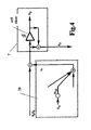
- Such a demodulator is shown in Figure 1.
- the received signal is filtered by a filter 1, and converted into digital form in an analogue-to digital converter 2.
- the digitised samples are entered into a buffer 3, synchronisation being provided by a control unit 4 so that, for each symbol, a block of 512 samples is assembled in the buffer.
- each z j being multiplied by a complex number to compensate for delay and attenuation suffered by the relevant carrier, and then fed to a QAM decoder 7 (usually employing some form of convolutional code and a soft-decision decoder), whereby the desired data values are recovered.
- a QAM decoder 7 usually employing some form of convolutional code and a soft-decision decoder
- One of the functions of the control unit 4, in addition to synchronisation, is to engage, at start-up, in a training sequence, that is, a dialogue with the transmitting modulator in which it obtains the information it needs about the transmitted signal, for example, which sub-channels are actually in use, how many bits are carried by each sub-channel, and what QAM constellations are being used by the modulator. In some systems, these parameters may be changed dynamically by further negotiation between the two ends during actual transmission. It is noted that the timing output from the control unit 4 serves for synchronisation of the various parts, whilst the control output indicates which sub-channels, and which constellations, are currently in use.
- US-A-6035000 and WO97/40608 both disclose methods of receiving signals comprising a plurality of sub-channels occupying different but mutually overlapping portions of frequency spectrum, comprising separating the signals into component signals corresponding to the respective sub-channels, calculating interference estimates for at least some of said sub-channels; and using the interference estimates to cancel interference from the respective component signals. Both make use of the component signals corresponding to sub-channels bearing no transmitted data.
- US-A-6035000 describes a system in which interference on a particular channel is estimated by measuring the signal on a nearby "quiet tone" on which no signal is transmitted, and multiplying it by a factor.
- WO97/40608 discloses the detection of interfering signals by sampling tones on which no data is transmitted, and using the results to estimate parameters of a frequency-domain model of the interference. The model is then used to estimate the interference which is then subtracted.
- the general aim of the receiver now to be described is based on the observation that, where a sub-channel has, owing to the presence of interference, been taken out of use, the signals received on that sub-channel will consist only of some component of the interfering signal, along with additive white Gaussian noise. Consequently it aims to deduce from the signals received on the idle sub-channel some knowledge about the nature of the interfering signal and use this knowledge to apply a correction to the signals received on the other sub-channels.
- Sub-channels in which the transmitted signal is known e.g. pilot tones
- Sub-channels carrying data can also be used in the same way if the signal component is firstly estimated and subtracted.
- the idea that the received signal on an idle sub-channel can allow one to infer something about the interference on some other sub-channel implies a correlation between the interference on the two channels. It follow that it is not possible to compensate for true white noise.
- the receiver shown in Figure 2 has the same basic structure as in Figure 1, but additionally has an interference cancellation unit 21 which calculates corrections c p to be made, and these are subtracted in subtractors S p from the sub-channel values.
- the correction occurs after the scaling unit 6 so that the corrected value is a p ⁇ z p - c p where a p is the relevant scale factor.
- the correction c p is a weighted sum of the scaled sub-channel values a p z p for the idle sub-channels.
- c p ⁇ q a q ⁇ z q ⁇ w qp
- ⁇ q is the estimated data content for a data-carrying sub-channel - for example, in a QAM system, the (complex) coordinate of that point of the QAM constellation which has the smallest Euclidean distance from the (complex) value represented by a q z q .
- a hard slicer 211 The same method may be used for determining ⁇ q for an idle or predictable sub-channel, but it is probably preferable to force ⁇ q to zero (or the known expected value) in such cases.
- the weighting factors w qp may simply be fixed. We prefer, however to calculate the weighting factors taking into account the characteristics of the signals actually received. One method of doing this will now be described.
- the decoder 7 can be a conventional decoder. If e p should be required for an idle sub-channel (e.g. for calculating weights w pq prior to bringing the sub-channel back into service) x p can be forced to zero.
- the calculation of the weighting factors is shown as performed in the unit 22.
- the aim is to minimise the average
- the following analysis works by considering
- the direction of the steepest ascent is the vector of all the partial derivatives of
- an adjustment to the weights to be made so as to give an updated weight to be used for the next symbol given by u qp - ⁇ .2 Re - e p . n q * v qp - ⁇ .2 Im - e p . n q *
- ⁇ is a small positive constant ( ⁇ 1) which controls the rate of training and may be varied from time to time but at any given time the same for all q , p .
- w qp k w qp ⁇ k - 1 + 2 ⁇ ⁇ . e p ⁇ k - 1 . n q * ⁇ k - 1 where a(k) denotes the value of a for symbol k .
- the task of the unit 20 is simply to calculate (once for each block) 2 ⁇ ⁇ . e p . n q * , , add it to the current value of W qp , and supply the new value of W qp to the correction unit 21.
- the initial value of W qp can be set to zero (0+ i 0).
- the postulated interference is white noise of constant power spectral density over a frequency range slightly narrower than that corresponding to the idle sub-channels.
- the white noise would be of a constant power over the frequency range corresponding to subchannels 55.5 to 60.1.
- the task of finding the weights is to find for each wanted subchannel k the values of w km that minimise S k .
- This can conveniently be accomplished by using one of the standard minimisation methods, for example the Fletcher-Reeves-Polak-Riviere method (this and other such methods are described in Presteukolsky, Vetterling and Flannery, "Numerical Recipes in C", Cambridge University Press, 2 nd Edition, 1992).
- This table shows the changes in noise ingress into each sub-channel (marked "bin") as a result of the correction.
- RFI noise ingress decreases (the decrease is an average for narrowband RF tones of unknown frequency in the band) while wideband AWGN ingress increases.
- Figure 6 is a graph showing the susceptibility of the ten corrected subchannels, overplotted. Each bin has a main lobe roughly where its uncorrected main lobe is, and sidelobes which fall away as 1/f 2 rather similar to the uncorrected subchannel, but with the sidelobes in the noise band about 30 dB lower than the uncorrected subchannel.
- these subchannels are not affected by each others' legitimate signals; the legitimate output of the transmit end of the DMT link only contributes into a subchannel from that subchannel's proper signal and the signals in the notch subchannels - which all have zero signals.
- the slicers, multipliers and subtractors shown in units 10, 11, 20, 22 in the drawings are largely schematic: although the receivers could be built this way, we prefer to implement the processes we describe using a suitable programmed digital signal processing (DSP) chip. Although these units could be implemented as individual such chips, a single one could be used: indeed if desired a single DSP could be used to implement these functions along with the conventional signal processing required of such a receiver, including the FFT calculations, the equalization, the quantisation, the trellis code decoding and the synchronisation processes which keep the receiver in step with the transmitter. The same device may also be executing the dialogue with the transmitter about bit reallocation and so on.
- DSP programmed digital signal processing
Landscapes
- Engineering & Computer Science (AREA)
- Computer Networks & Wireless Communication (AREA)
- Signal Processing (AREA)
- Noise Elimination (AREA)
Abstract
Claims (21)
- Procédé de réception de signaux comprenant une pluralité de sous-canaux occupant des parties différentes mais se chevauchant mutuellement du spectre de fréquences, comprenant les étapes consistant à :séparer les signaux en signaux composants correspondant aux sous-canaux respectifs,calculer des estimations d'interférences pour au moins certains desdits sous-canaux, d'après les signaux composants correspondant à des sous-canaux de référence parmi lesdits sous-canaux, lesdits sous-canaux de référence étant un ou plusieurs sous-canaux parmi (a) des sous-canaux ne portant aucune donnée transmise, (b) des sous-canaux ayant un contenu fixe qui peut être soustrait pour obtenir une estimation d'interférence et (c) des sous-canaux ayant un contenu qui peut être estimé et soustrait pour obtenir une estimation d'interférence,soustraire les estimations d'interférences des signaux composants respectifs pour produire des signaux composants ajustés,dans lequel, pour tout sous-canal particulier, l'estimation d'interférence pour celui-ci est calculée sous la forme d'une somme pondérée du contenu d'interférence des signaux composants de certains desdits sous-canaux de référence, en excluant le sous-canal particulier pour lequel l'estimation doit être utilisée, et comprenant l'étape consistant à sélectionner des coefficients de pondération pour lesdites sommes pondérées en mesurant les erreurs dans le sous-canal particulier et en ajustant les coefficients de pondération dans un sens tel qu'il tend à réduire ladite erreur.
- Procédé selon la revendication 1, utilisable avec des transmissions dans lesquelles les signaux dans les sous-canaux sont autorisés à ne prendre que certaines valeurs permises, le procédé comprenant l'estimation, à partir du signal composant pour un sous-canal donné, de celle des valeurs permises qu'il représente, et la détermination de l'erreur du sous-canal en soustrayant ladite valeur permise estimée du signal composant ajusté pour ce sous-canal.
- Procédé selon la revendication 2, dans lequel l'estimation, de la valeur permise qu'un signal composant représente, est exécutée par un décodeur à décision pondérée.
- Procédé de réception de signaux comprenant une pluralité de sous-canaux occupant des parties différentes mais se chevauchant mutuellement du spectre de fréquences, comprenant les étapes consistant à :séparer les signaux en signaux composants correspondant aux sous-canaux respectifs,calculer des estimations d'interférences pour au moins certains desdits sous-canaux, d'après les signaux composants correspondant à des sous-canaux de référence parmi lesdits sous-canaux, lesdits sous-canaux de référence étant un ou plusieurs sous-canaux parmi (a) des sous-canaux ne portant aucune donnée transmise, (b) des sous-canaux ayant un contenu fixe qui peut être soustrait pour obtenir une estimation d'interférence et (c) des sous-canaux ayant un contenu qui peut être estimé et soustrait pour obtenir une estimation d'interférence,soustraire les estimations d'interférences des signaux composants respectifs pour produire des signaux composants ajustés,dans lequel, pour tout sous-canal particulier, l'estimation d'interférence pour celui-ci est calculée sous la forme d'une somme pondérée du contenu d'interférence des signaux composants de certains desdits sous-canaux de référence, en excluant le sous-canal particulier pour lequel l'estimation doit être utilisée, et le procédé comprend l'étape consistant à sélectionner des coefficients de pondération pour lesdites sommes pondérées en définissant un signal d'interférence supposé, à déterminer les composants de sous-canaux qui seraient reçus, si les signaux reçus devaient consister en le signal d'interférence supposé seul, et à ajuster les coefficients de pondération pour ledit sous-canal particulier de manière à tendre à réduire l'amplitude de la différence entre le composant de sous-canal dans le sous-canal respectif et la somme pondérée desdits composants de sous-canaux déterminés en raison du signal d'interférence supposé.
- Procédé selon la revendication 4, dans lequel le signal d'interférence supposé est un signal de bruit blanc occupant une ou plusieurs parties définies dudit spectre de fréquences.
- Procédé selon la revendication 5, comprenant la réception de signaux identifiant un ou plusieurs sous-canaux inactifs, et la définition de la partie ou de chaque partie définie du spectre comme s'étendant à l'intérieur d'une plage de fréquences correspondant à un sous-canal inactif ou à une pluralité de sous-canaux inactifs adjacents.
- Procédé selon l'une quelconque des revendications 1 à 6, dans lequel les coefficients de pondération sont sélectionnés une fois.
- Procédé selon l'une quelconque des revendications 1 à 6, dans lequel les coefficients de pondération sont à nouveau sélectionnés après un changement dans la sélection des sous-canaux de référence.
- Procédé selon l'une quelconque des revendications 1 à 8, comprenant la réception de signaux identifiant des sous-canaux inactifs, le contenu d'interférence du sous-canal étant le signal composant pour ce sous-canal.
- Procédé selon l'une quelconque des revendications 1 à 9, comprenant la réception de signaux identifiant des sous-canaux contenant des signaux connus, et la détermination du contenu d'interférence du sous-canal en soustrayant ledit contenu connu du signal composant pour ce sous-canal.
- Procédé selon l'une quelconque des revendications 4 à 6, à utiliser avec des transmissions dans lesquelles les signaux dans les sous-canaux sont autorisés à ne prendre que certaines valeurs permises, le procédé comprenant une estimation, à partir du signal composant pour un sous-canal donné, de la valeur parmi les valeurs permises qu'il représente, et la détermination du contenu d'interférence du sous-canal en soustrayant ladite valeur permise estimée du signal composant pour ce sous-canal.
- Récepteur de signaux comprenant une pluralité de sous-canaux occupant des parties différentes mais se chevauchant mutuellement du spectre de fréquences, comprenant :un moyen destiné à séparer les signaux en signaux composants correspondant aux sous-canaux respectifs,un moyen (20, 21) destiné à calculer des estimations d'interférences pour au moins certains desdits sous-canaux d'après les signaux composants (zi) correspondant aux sous-canaux de référence parmi lesdits sous-canaux, lesdits sous-canaux de référence étant un ou plusieurs sous-canaux parmi (a) des sous-canaux ne portant aucune donnée transmise, (b) des sous-canaux ayant un contenu fixe qui peut être soustrait pour obtenir une estimation d'interférence et (c) des sous-canaux ayant un contenu qui peut être estimé et soustrait pour obtenir une estimation d'interférence,un moyen (Sj) destiné à soustraire les estimations d'interférences des signaux composants respectifs (zj),dans lequel le moyen de calcul (20, 21) peut être mis en oeuvre pour tout sous-canal particulier pour calculer l'estimation d'interférence pour celui-ci sous la forme d'une somme pondérée du contenu d'interférence des signaux composants de certains desdits sous-canaux de référence, en excluant le sous-canal particulier pour lequel l'estimation doit être utilisée, et dans lequel le moyen de calcul (20, 21) peut être mis en oeuvre pour tout sous-canal particulier afin de sélectionner des coefficients de pondération pour lesdites sommes pondérées en mesurant des erreurs dans le sous-canal particulier et en ajustant les coefficients de pondération dans un sens tel qu'il tend à réduire ladite erreur.
- Récepteur selon la revendication 12, à utiliser avec des transmissions dans lesquelles les signaux dans les sous-canaux sont autorisés à ne prendre que certaines valeurs permises, le moyen de calcul comprend un moyen (211) destiné à estimer, à partir du signal composant pour un sous-canal donné, la valeur parmi les valeurs permises qu'il représente, et à déterminer l'erreur du sous-canal en soustrayant ladite valeur permise estimée du signal composant ajusté pour ce sous-canal.
- Récepteur selon la revendication 13, dans lequel le moyen d'estimation de valeur permise et de détermination d'erreur (211) est un décodeur à décision pondérée.
- Récepteur pour des signaux comprenant une pluralité de sous-canaux occupant des parties différentes mais se chevauchant mutuellement du spectre de fréquences comprenant :un moyen destiné à séparer les signaux en signaux composants correspondant aux sous-canaux respectifs,un moyen (20, 21) destiné à calculer des estimations d'interférences pour au moins certains des sous-canaux sur la base des signaux composants (zj) correspondant aux sous-canaux de référence parmi lesdits sous-canaux, lesdits sous-canaux de référence étant un ou plusieurs sous-canaux parmi (a) des sous-canaux ne portant aucune donnée transmise, (b) des sous-canaux ayant un contenu fixe qui peut être soustrait pour obtenir une estimation d'interférence et (c) des sous-canaux ayant un contenu qui peut être estimé et soustrait pour obtenir une estimation d'interférence,un moyen (Sj) destiné à soustraire les estimations d'interférences des signaux composants respectifs (zj),dans lequel le moyen de calcul (20, 21) peut être mis en oeuvre pour tout sous-canal particulier afin de calculer l'estimation d'interférence pour celui-ci sous la forme d'une somme pondérée du contenu d'interférence des signaux composants de certains desdits sous-canaux de référence, en excluant le sous-canal particulier pour lequel l'estimation doit être utilisée, et comprenant un moyen (20) destiné à sélectionner les coefficients de pondération pour lesdites sommes pondérées en définissant un signal d'interférence supposé, en déterminant les composants de sous-canaux qui seraient reçus si les signaux reçus devaient consister en le signal d'interférence supposé seul, et en ajustant les coefficients de pondération pour ledit sous-canal particulier de manière à tendre à réduire l'amplitude de la différence entre le composant de sous-canal dans le sous-canal respectif et la somme pondérée desdits composants de sous-canaux déterminés du fait du signal d'interférence supposé.
- Récepteur selon la revendication 15, dans lequel le signal d'interférence supposé est un signal de bruit blanc occupant une ou plusieurs parties définies dudit spectre de fréquences.
- Récepteur selon la revendication 16, comprenant un moyen destiné à recevoir les signaux identifiant un ou plusieurs sous-canaux inactifs, et définissant la partie ou chaque partie définie du spectre comme s'étendant à l'intérieur d'une plage de fréquences correspondant à un sous-canal inactif ou à une pluralité de sous-canaux inactifs adjacents.
- Récepteur selon la revendication 15, 16 ou 17, dans lequel le moyen (20) destiné à sélectionner les coefficients de pondération peut être mis en oeuvre pour resélectionner les coefficients de pondération après un changement dans la sélection des sous-canaux de référence.
- Récepteur selon l'une quelconque des revendications 12 à 18, comprenant un moyen recevant des signaux identifiant des sous-canaux inactifs, le contenu d'interférence du sous-canal étant le signal composant pour ce sous-canal.
- Récepteur selon l'une quelconque des revendications 12 à 19 comprenant un moyen recevant des signaux identifiant des sous-canaux contenant des signaux connus, et destiné à déterminer le contenu d'interférence du sous-canal en soustrayant ledit contenu connu du signal composant pour ce sous-canal.
- Récepteur selon l'une quelconque des revendications 15 à 18 à utiliser avec des transmissions dans lesquelles les signaux dans les sous-canaux sont autorisés à ne prendre que certaines valeurs permises, et comprenant un moyen destiné à estimer, à partir du signal composant pour un sous-canal donné, la valeur parmi les valeurs permises qu'il représente, et à déterminer le contenu d'interférence du sous-canal en soustrayant ladite valeur permise estimée du signal composant pour ce sous-canal.
Priority Applications (1)
| Application Number | Priority Date | Filing Date | Title |
|---|---|---|---|
| EP02783276A EP1451992B1 (fr) | 2001-12-07 | 2002-12-05 | Elimination d'interférences dans des récepteurs multiporteuses |
Applications Claiming Priority (4)
| Application Number | Priority Date | Filing Date | Title |
|---|---|---|---|
| EP01310258A EP1318642A1 (fr) | 2001-12-07 | 2001-12-07 | Annulation d'infterférences dans des récepteurs multiporteuses |
| EP01310258 | 2001-12-07 | ||
| PCT/GB2002/005501 WO2003049396A2 (fr) | 2001-12-07 | 2002-12-05 | Modulation multiporteuse |
| EP02783276A EP1451992B1 (fr) | 2001-12-07 | 2002-12-05 | Elimination d'interférences dans des récepteurs multiporteuses |
Publications (2)
| Publication Number | Publication Date |
|---|---|
| EP1451992A2 EP1451992A2 (fr) | 2004-09-01 |
| EP1451992B1 true EP1451992B1 (fr) | 2007-06-27 |
Family
ID=8182521
Family Applications (2)
| Application Number | Title | Priority Date | Filing Date |
|---|---|---|---|
| EP01310258A Withdrawn EP1318642A1 (fr) | 2001-12-07 | 2001-12-07 | Annulation d'infterférences dans des récepteurs multiporteuses |
| EP02783276A Expired - Lifetime EP1451992B1 (fr) | 2001-12-07 | 2002-12-05 | Elimination d'interférences dans des récepteurs multiporteuses |
Family Applications Before (1)
| Application Number | Title | Priority Date | Filing Date |
|---|---|---|---|
| EP01310258A Withdrawn EP1318642A1 (fr) | 2001-12-07 | 2001-12-07 | Annulation d'infterférences dans des récepteurs multiporteuses |
Country Status (6)
| Country | Link |
|---|---|
| US (1) | US8223852B2 (fr) |
| EP (2) | EP1318642A1 (fr) |
| AU (1) | AU2002347340A1 (fr) |
| CA (1) | CA2467080A1 (fr) |
| DE (1) | DE60220942T2 (fr) |
| WO (1) | WO2003049396A2 (fr) |
Families Citing this family (5)
| Publication number | Priority date | Publication date | Assignee | Title |
|---|---|---|---|---|
| DE102004047718B4 (de) * | 2004-09-30 | 2009-01-02 | Infineon Technologies Ag | Verfahren und Empfängerschaltung zur Reduzierung von RFI-Störungen |
| US8942639B2 (en) | 2005-03-15 | 2015-01-27 | Qualcomm Incorporated | Interference control in a wireless communication system |
| US8848574B2 (en) | 2005-03-15 | 2014-09-30 | Qualcomm Incorporated | Interference control in a wireless communication system |
| KR101097021B1 (ko) | 2005-10-27 | 2011-12-20 | 콸콤 인코포레이티드 | 무선 통신 시스템에서 역방향 링크 로딩을 추정하기 위한 방법 및 장치 |
| DE102009012315B4 (de) * | 2009-03-09 | 2012-03-01 | Continental Automotive Gmbh | Verfahren zum Transport von Daten im Automobil |
Family Cites Families (10)
| Publication number | Priority date | Publication date | Assignee | Title |
|---|---|---|---|---|
| WO1987006368A1 (fr) | 1986-04-11 | 1987-10-22 | Ampex Corporation | Appareil et procede pour le codage et le decodage de donnees d'attributs dans les symboles de controle d'erreur de donnees principales |
| AU687286B2 (en) | 1994-12-12 | 1998-02-19 | Stratos Global Limited | Digital transmission system for encoding and decoding attribute data into error checking symbols of main data |
| US6014412A (en) * | 1996-04-19 | 2000-01-11 | Amati Communications Corporation | Digital radio frequency interference canceller |
| US6035000A (en) * | 1996-04-19 | 2000-03-07 | Amati Communications Corporation | Mitigating radio frequency interference in multi-carrier transmission systems |
| US5995567A (en) * | 1996-04-19 | 1999-11-30 | Texas Instruments Incorporated | Radio frequency noise canceller |
| FR2808635B1 (fr) * | 2000-05-02 | 2002-08-02 | Sagem | Annulation de signaux perturbants dans un recepteur de modem xdsl |
| US6556623B2 (en) * | 2000-06-09 | 2003-04-29 | Aware, Inc. | Systems and methods for a multi-carrier transceiver with radio frequency interference reduction |
| US20020027985A1 (en) * | 2000-06-12 | 2002-03-07 | Farrokh Rashid-Farrokhi | Parallel processing for multiple-input, multiple-output, DSL systems |
| US7366088B2 (en) * | 2000-09-12 | 2008-04-29 | Siemens Aktiengesellschaft | Method and orthogonal frequency division multiplexing (OFDM) receiver for reducing the influence of harmonic interference on OFDM transmission systems |
| US7697594B2 (en) * | 2001-03-30 | 2010-04-13 | Texas Instruments Incorporated | Method and apparatus for regenerative based interference cancellation within a communication system |
-
2001
- 2001-12-07 EP EP01310258A patent/EP1318642A1/fr not_active Withdrawn
-
2002
- 2002-12-05 CA CA002467080A patent/CA2467080A1/fr not_active Abandoned
- 2002-12-05 US US10/495,622 patent/US8223852B2/en active Active
- 2002-12-05 DE DE60220942T patent/DE60220942T2/de not_active Expired - Lifetime
- 2002-12-05 AU AU2002347340A patent/AU2002347340A1/en not_active Abandoned
- 2002-12-05 WO PCT/GB2002/005501 patent/WO2003049396A2/fr not_active Ceased
- 2002-12-05 EP EP02783276A patent/EP1451992B1/fr not_active Expired - Lifetime
Non-Patent Citations (1)
| Title |
|---|
| None * |
Also Published As
| Publication number | Publication date |
|---|---|
| WO2003049396A2 (fr) | 2003-06-12 |
| DE60220942D1 (de) | 2007-08-09 |
| EP1451992A2 (fr) | 2004-09-01 |
| US20050084024A1 (en) | 2005-04-21 |
| AU2002347340A8 (en) | 2003-06-17 |
| CA2467080A1 (fr) | 2003-06-12 |
| DE60220942T2 (de) | 2008-02-28 |
| WO2003049396A3 (fr) | 2003-07-24 |
| EP1318642A1 (fr) | 2003-06-11 |
| AU2002347340A1 (en) | 2003-06-17 |
| US8223852B2 (en) | 2012-07-17 |
Similar Documents
| Publication | Publication Date | Title |
|---|---|---|
| CN101341677B (zh) | 载波间干涉去除装置及使用其的接收装置 | |
| KR100555508B1 (ko) | 직교 주파수 분할 다중 수신 시스템에서의 임펄스 잡음억제 회로 및 방법 | |
| EP1459489B1 (fr) | Egalisation, demapping pondere et correction d'erreur de phase conjoints dans un systeme sans fil a diversite de reception | |
| US10084495B2 (en) | Method for frequency—and time-selective interference suppression for a communication system based on OFDM, and receiver therefor | |
| US6449324B2 (en) | Digital radio frequency interference canceller | |
| KR100505694B1 (ko) | 직접 계산 방식에 의한 코드화 직교 주파수 분할 다중화수신기의 채널 상태 평가 장치 및 그 방법 | |
| RU2235435C2 (ru) | Способ оценки отношения "сигнал-шум" цифровых несущих в системе широковещательной передачи цифровых аудиосигналов, совместимых с амплитудно-модулированными сигналами | |
| US7623569B2 (en) | Apparatus and method for estimating interference and noise in a communication system | |
| US7532567B2 (en) | Radio communication system, radio transmitter and radio receiver | |
| CN100448184C (zh) | 正交频分多路复用系统的接收机 | |
| US7499509B2 (en) | Receiver for compensating nonlinearly distorted multicarrier signals | |
| US7961806B2 (en) | Power adaptive channel estimation for a multi-path receiving | |
| US20090016468A1 (en) | Method for error compensation in an ofdm system with diversity | |
| CN102090035B (zh) | 用于对通信系统中的残留频率误差进行估计的方法和设备 | |
| KR20010075490A (ko) | 호환성 디지털 오디오 방송시스템의 상보성 캐리어이퀄라이제이션 방법 | |
| US7443782B2 (en) | Adaptive inter-carrier interference self-cancellation method and transceiver thereof | |
| US7319659B2 (en) | OFDM receiver, mode detector therefor, and method for processing OFDM signals | |
| EP0963086A2 (fr) | Dispositif de correction d'erreurs pour le traitement de bruit sélectif en fréquence | |
| JP2004080731A (ja) | Ofdm受信装置及びofdm信号の補正方法 | |
| WO2006003964A1 (fr) | Dispositif de detection de signal perturbant et dispositif de reception ofdm utilisant celui-ci | |
| EP1451992B1 (fr) | Elimination d'interférences dans des récepteurs multiporteuses | |
| KR100602518B1 (ko) | 직교주파수분할다중 통신 시스템의 채널 추정 방법 및 장치 | |
| KR100464577B1 (ko) | 디지탈무선주파수간섭소거기 | |
| KR100195261B1 (ko) | 다중 반송파 수신기 | |
| JP2007104574A (ja) | マルチキャリア無線受信機及び受信方法 |
Legal Events
| Date | Code | Title | Description |
|---|---|---|---|
| PUAI | Public reference made under article 153(3) epc to a published international application that has entered the european phase |
Free format text: ORIGINAL CODE: 0009012 |
|
| 17P | Request for examination filed |
Effective date: 20040517 |
|
| AK | Designated contracting states |
Kind code of ref document: A2 Designated state(s): AT BE BG CH CY CZ DE DK EE ES FI FR GB GR IE IT LI LU MC NL PT SE SI SK TR |
|
| AX | Request for extension of the european patent |
Extension state: AL LT LV MK RO |
|
| 17Q | First examination report despatched |
Effective date: 20041021 |
|
| GRAP | Despatch of communication of intention to grant a patent |
Free format text: ORIGINAL CODE: EPIDOSNIGR1 |
|
| GRAS | Grant fee paid |
Free format text: ORIGINAL CODE: EPIDOSNIGR3 |
|
| GRAA | (expected) grant |
Free format text: ORIGINAL CODE: 0009210 |
|
| AK | Designated contracting states |
Kind code of ref document: B1 Designated state(s): DE FR GB |
|
| REG | Reference to a national code |
Ref country code: GB Ref legal event code: FG4D |
|
| REF | Corresponds to: |
Ref document number: 60220942 Country of ref document: DE Date of ref document: 20070809 Kind code of ref document: P |
|
| ET | Fr: translation filed | ||
| PLBE | No opposition filed within time limit |
Free format text: ORIGINAL CODE: 0009261 |
|
| STAA | Information on the status of an ep patent application or granted ep patent |
Free format text: STATUS: NO OPPOSITION FILED WITHIN TIME LIMIT |
|
| 26N | No opposition filed |
Effective date: 20080328 |
|
| REG | Reference to a national code |
Ref country code: FR Ref legal event code: PLFP Year of fee payment: 14 |
|
| REG | Reference to a national code |
Ref country code: FR Ref legal event code: PLFP Year of fee payment: 15 |
|
| REG | Reference to a national code |
Ref country code: FR Ref legal event code: PLFP Year of fee payment: 16 |
|
| PGFP | Annual fee paid to national office [announced via postgrant information from national office to epo] |
Ref country code: DE Payment date: 20211117 Year of fee payment: 20 Ref country code: FR Payment date: 20211118 Year of fee payment: 20 Ref country code: GB Payment date: 20211118 Year of fee payment: 20 |
|
| REG | Reference to a national code |
Ref country code: DE Ref legal event code: R071 Ref document number: 60220942 Country of ref document: DE |
|
| REG | Reference to a national code |
Ref country code: GB Ref legal event code: PE20 Expiry date: 20221204 |
|
| PG25 | Lapsed in a contracting state [announced via postgrant information from national office to epo] |
Ref country code: GB Free format text: LAPSE BECAUSE OF EXPIRATION OF PROTECTION Effective date: 20221204 |