EP1452109A1 - Applikator für ein Produkt, insbesondere für Kosmetik - Google Patents
Applikator für ein Produkt, insbesondere für Kosmetik Download PDFInfo
- Publication number
- EP1452109A1 EP1452109A1 EP04290413A EP04290413A EP1452109A1 EP 1452109 A1 EP1452109 A1 EP 1452109A1 EP 04290413 A EP04290413 A EP 04290413A EP 04290413 A EP04290413 A EP 04290413A EP 1452109 A1 EP1452109 A1 EP 1452109A1
- Authority
- EP
- European Patent Office
- Prior art keywords
- piston
- product
- envelope
- opening
- wall
- Prior art date
- Legal status (The legal status is an assumption and is not a legal conclusion. Google has not performed a legal analysis and makes no representation as to the accuracy of the status listed.)
- Granted
Links
Images


Classifications
-
- A—HUMAN NECESSITIES
- A45—HAND OR TRAVELLING ARTICLES
- A45D—HAIRDRESSING OR SHAVING EQUIPMENT; EQUIPMENT FOR COSMETICS OR COSMETIC TREATMENTS, e.g. FOR MANICURING OR PEDICURING
- A45D40/00—Casings or accessories specially adapted for storing or handling solid or pasty toiletry or cosmetic substances, e.g. shaving soaps or lipsticks
- A45D40/02—Casings wherein movement of the lipstick or like solid is a sliding movement
- A45D40/04—Casings wherein movement of the lipstick or like solid is a sliding movement effected by a screw
Definitions
- the present invention relates to an application device intended for application topically, with a cosmetic or dermatopharmaceutical product, such as a deodorant product, a moisturizer, a protective product sunscreen, lipstick, foundation, eye shadow, product styling, hair coloring product, etc.
- a cosmetic or dermatopharmaceutical product such as a deodorant product, a moisturizer, a protective product sunscreen, lipstick, foundation, eye shadow, product styling, hair coloring product, etc.
- the invention relates to a device for applying a product solid such as a stick product or a fluid product having an applicator wall permeable to the product.
- stick products are packaged in devices of the type comprising a cup in which the formula to be applied is found, and which, in response to a actuation control, move axially inside a jacket between a storage position and an application position.
- the mechanism of entrainment of the cup in its axial displacement can be various. he may be a threaded rod disposed under the cup, cooperating with a member forming a nut, such a mechanism being controlled by a maneuver formed by a wheel arranged under the shirt. Alternatively, it may be a helical ramp produced in a wall of the jacket, and in which a lug carried by the cup moves.
- Stick products including deodorant products, can be packaged in other types of devices which include a piston sliding inside a shirt.
- the piston can be driven by a rod threaded cooperating with a nut, or even by a ratchet mechanism.
- US Patent 1,637,545 describes an eyebrow pencil which includes a tube in which is housed a stick of product.
- the tube is closed by a bottom at a first end and open at its opposite end to let out the product stick.
- the product stick is mounted in a bucket which slides at inside the tube and which comes into elastic support along the side wall of the tube.
- a ball is housed inside the tube, between the bucket and the bottom of the envelope, in a space configured to allow it to move in the axis of the tube.
- the user shakes the pencil so that the ball strikes the bucket and raises the stick in the tube.
- the bucket being in elastic support on the side wall of the tube, it is necessary that the bucket is in contact with sufficient friction on the side wall of the tube so that the stick of product does not move back into the tube during application.
- the friction is too great, it is very difficult to raise the bucket inside the tube to get the stick out before application, in particular during the first uses where the ball does not can't take much speed. It is then necessary to shake vigorously the pencil to manage to bring out the stick of product.
- substantially constant maximum amplitude is meant an amplitude maximum which remains constant as the device is used but also a maximum amplitude which can vary slightly, as and measurement of the use of the device, but from a short distance. For example, this variation is less than or equal to the axial height of the movable element, and preferably less than or equal to half the axial height of the element mobile.
- the mobile element has a substantially constant travel. Consequently, for the same agitation of the device, the force with which the movable element strikes the piston is essentially the same so that the product moves roughly the same distance.
- the drive member being located inside the envelope, it is not not accessible from the outside which makes it possible to produce a device whose the external appearance, in particular the decor, is not encumbered by the body drive.
- the movable member can be coupled to the piston in different ways.
- the element mobile can be housed in a cage integral with the piston.
- the movable element can be connected to the piston by at least one flexible arm.
- the movable element can be slidably mounted on at minus a rod secured to the piston.
- the movement of the movable element can be guided inside the device.
- it when it is housed in a cage, it can be configured in such a way that the movable element can only move parallel to the X axis.
- the mobile element being guided in its movement, its movement is properly controlled by the user who shakes the device. Therefore, the user also controls the displacement of the piston and therefore the output of the product.
- the device may include means forming a stop to prevent the piston to move in the opposite direction to the direction of opening, especially when applying the product.
- the stop means can be formed by the cooperation of at least one radial tooth provided on a wall integral with the piston with at least one radial tooth provided on a second wall.
- the device may include means for deactivating the means forming stop in order to allow the piston to move in the opposite direction to the opening direction.
- the means for deactivating the means forming a stop may be constituted by flexible legs capable of tilting so as to laterally spread the tooth of the second wall of the tooth from the integral wall piston.
- the means for deactivating the means forming stop may include a gripping portion integral with the second wall capable of rotating the second wall relative to the wall integral with the piston, so as to bring the tooth of the second wall opposite a portion of the wall integral with the piston devoid of tooth.
- the mobile element can be a ball or a mass of any other shape.
- the end of the housing can define an opening of cross section identical to the cross section of the envelope, suitable for letting the produced in stick form.
- the end of the housing can have a wall permeable to the product in fluid form.
- Wall permeable has at least one opening and preferably a plurality openings, capable of allowing the product to pass in fluid form.
- the size of openings is chosen according to the viscosity of the product so that that the product cannot flow by simple gravity through the openings.
- the openings can for example be the pores of a porous material or the spaces between the fibers of a fibrous material.
- the piston may include a peripheral lip capable of sliding so waterproof on the inner surface of the envelope.
- a peripheral lip capable of sliding so waterproof on the inner surface of the envelope.
- the product is for example a cosmetic product, in particular a product deodorant, a moisturizer, a sun protection product, a red to lips, foundation, eye shadow, styling product or hair coloring product.
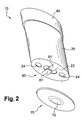
- Figures 1 to 4 show a first example of a device 10 according to the invention.
- the application device is for example intended for the application of a cosmetic product, in particular a product deodorant, and comes in the form of a solid stick.
- the device 10 has a longitudinal axis X and a cross section elliptical.
- the device comprises a piston 30 and an envelope 20 in which the piston 30 can slide axially, as well as a cap closure 40.
- the elliptical cross section allows in particular to allow a translational movement between the piston and the casing. It is well obvious that any other non-circular shape can have this function.
- the cross section can be circular and an anti-rotation system can be provided on the piston and the casing, such as for example a sliding lug in an axial groove.
- the device can also have a circular cross section and not have any anti-rotation system and thus allow a rotational movement between the casing and the piston.
- the envelope 20 forms the external wall of the device and delimits laterally, in its upper part, the housing for the product while the piston 30 forms the bottom of the housing for the product.
- the envelope 20 is formed by a sleeve extending parallel to the axis X and has an elliptical cross section.
- the envelope 20 is open to its upper end 21 in order to delimit an opening 22 allowing the passage of the product.
- the lower end of the envelope 20 is partly closed by a transverse wall 23.
- the transverse wall 23 has two orifices 24 allowing the filling of product.
- the piston 30 has a transverse wall 31, of elliptical shape, the upper side receives the product.
- a transverse wall 31 of elliptical shape, the upper side receives the product.
- fins not shown
- any other surface rough on the upper surface of the transverse wall 31 on which hangs the product when it is poured inside the envelope.
- Wall transverse 31 is crossed by a circular central opening 32, the function will be explained later, closed by a plug 35 which comes snap for example into the wall 31.
- the transverse wall 31 is also crossed by two orifices 33 allowing filling with product.
- the transverse wall 31 has at its periphery a sealing lip 34 designed to slide tightly on the envelope in order to move the product. The lip slides on the envelope with a force of necessary and sufficient friction to seal the product, all allowing the user to easily move it.
- the device also includes a drive member 50, arranged under the piston 30, and provided to move the piston 30 axially relative to the envelope to remove the product from the envelope.
- the driving organ 50 comprises a ball 51 housed in a cage 52 secured to the piston and in which can move the ball.
- the cage is formed by two arc walls 53 of circle which extend around the opening 32, parallel to the X axis, towards the bottom of the envelope.
- the two walls 53 are arranged so that their concavity is opposite one another. They thus delimit laterally the cage 52 of substantially cylindrical shape of revolution.
- the two walls 53 are secured at their lower end to a disc 54 constituting the bottom of cage 52.
- the dimensions of the cage and the ball are such that the ball is able to move axially in the cage and cannot be substantially move transversely to the X axis.
- the device comprises a system of axial stop.
- the external surface of the walls 53 comprises, on substantially their entire axial height, radial teeth 530 oriented towards the bottom of the cage 52.
- These teeth 530 cooperate with radial teeth 560, provided on the internal surface of walls 56 integral with the envelope, on substantially their entire axial height, and on which they abut axial.
- the two walls 56 in an arc extend parallel to the axis X to from the transverse wall 23, with which they are integral, until an upper free end 57.
- the two walls 56 are arranged so that their concavity is opposite one another.
- the teeth radials 560 are arranged on the internal surface of the walls 56 and are oriented towards the opening 22 of the envelope.
- the lower edge 531 of the teeth 530 of the walls 53 integral with the piston is perpendicular to the X axis and the upper edge 562 of the teeth 560 of the walls 56 integral with the envelope is perpendicular to the X axis.
- the lower edge 531 teeth 530 therefore abuts against the upper edge 562 of teeth 560.
- each tooth 560 is inclined so as to form a ramp for the upper edge 532 of the teeth 530.
- the device also includes means 60 for deactivating the system axial stop allowing the user to lower the product stick towards the bottom of the envelope.
- the means 60 are for example constituted by elastic tabs 61 obtained by cutting in the transverse wall 23.
- the legs 61 are cut in such a way that they can pivot around an axis substantially perpendicular to the X axis so as to be able go inside the envelope.
- Legs 61 are formed just in below the walls 56 of which they are integral, so that the depression legs in the envelope spreads the walls 56 from the walls 53 and disengages teeth 560 teeth 530 to allow axial movement of the piston towards the bottom of the envelope.
- the device further comprises an attached bottom 70 intended to close the filling orifices 24.
- the bottom 70 is formed by a flat wall of shape elliptical which has two protrusions 71 provided to snap into the orifices 24 in order to close them.
- the bottom 70 also makes it possible to close the cutouts formed around the legs 61.
- the bottom 70 thus avoids fouling inside the envelope.
- the central part 72 of the bottom 70 located opposite the legs 61 is substantially curved inward of the envelope and relatively flexible to allow the insertion of the legs 61 through the bottom 70.
- a closing cap 40 is provided to close the opening 22 of the envelope. It is closed in part upper by a domed portion 41 and is open at its lower end 42.
- a radial projection 43 is provided on the internal surface of the cap, at near the lower end 42, to be housed in a groove 25 provided on the outer surface of the casing in order to fix the cap on the envelope.
- the cap can be attached to the envelope by lateral tightening.
- the device is produced in the following manner. First, the different component parts of the device are formed by molding a material thermoplastic, for example polypropylene, or polyethylene.
- a material thermoplastic for example polypropylene, or polyethylene.
- the piston 30 secured to the cage 52 is mounted in the casing 20 in position low, that is to say that the bottom of the cage 52 is positioned as close as possible to the transverse wall 23 of the envelope, between the walls 56.
- the ball 51 is introduced into the cage 52 through the opening 22 of the envelope, via the opening central 32 of the piston which is then closed by the plug 35.
- We can overcome the central opening 32 and the plug 35 by introducing the ball in the cage 52 by the openings delimited between the walls 53.
- the walls 53 are then elastic enough to be slightly apart so to introduce the ball and to return to their initial position so that the ball can no longer leave the cage.
- the cap 40 is then fixed reversibly on the envelope.
- the device is then filled with product in fluid form by making it flow through the bottom of the envelope, through orifices 24 and 33 to fill the housing defined by the envelope 20, the convex portion 41 of the cap and the transverse wall 31 of the piston.
- a small capsule which is fixed on the upper edge of the envelope 20 and which defines, with the envelope and the transverse wall 31, the volume of product to fill.
- a capsule having a domed shape of so as to obtain a surface for applying the curved product.
- the product in drying, forms a stick whose bottom is secured to the transverse wall 32 of the piston.
- a stick of solid product can be inserted inside of the housing, through the opening 22 of the envelope.
- the bottom 70 is then snapped into the transverse wall 23 of the envelope 20.
- the device shown in FIG. 3 is thus obtained.
- the user shakes the device so as to move the ball 51 in the cage 52.
- the ball 51 then strikes the transverse wall 31 of the piston which makes slide the piston inside the envelope towards the opening 22, from a height axial corresponding to at least one tooth.
- a tooth 530 is housed opposite tooth 560 located just above of the one next to which it was before the agitation, then next tooth 560 still located above if agitation continues.
- the part upper part of the product is then released from the envelope, so that the user can apply it on his body by holding the envelope, as we have shown in Figure 4.
- the edge 531 of the teeth 530 abutting against the edge 562 of teeth 560, the product cannot move back into the envelope during the application.
- the user In the case where the user has raised the stick too much, that is to say that too large a portion of the stick is released from the envelope, it just press on the curved portion 72 of the bottom 70 in order to push the legs 61 inside the envelope and laterally clear the walls 56 of the walls 53. By pressing on the upper surface of the stick, the user can then push the product inside the envelope.
- the means 60 for deactivating the abutment system which have just been described can be replaced by other means, for example those shown in Figures 5A to 5C.
- the walls 56 are extended by a gripping zone 58 accessible from outside the device and which can rotate the walls 56 with respect to the cage 52 and to the transverse wall 23.
- the walls 53 forming the cage comprise an angular portion provided with teeth 530 and a another angular portion 59 devoid of tooth.
- the walls 56 are angularly positioned opposite the portion of the walls 53 provided with teeth 530 of so that the teeth 530 abut against the teeth 560.
- the user turns the gripping portion 58 at an angle such that the teeth 560 come opposite the portion 59 of the walls 53 devoid of tooth, as shown in Figure 5C. The user can then push the product towards the bottom of the envelope.
- the drive member 40 which has just been described can be replaced by different variants such as those shown in Figures 6A to 6F.
- the ball 51 can be connected to the piston by means of a flexible arm 501 which allows the movement of the ball (see Figure 6A), or by two flexible arms (Figure 6B).
- the movable element can also be an elastomer ball which extends by two lateral arms 503, also made of elastomer. Each free end arms 503 is fixed to an axial rod 504 secured to piston 30.
- the mobile element can also be slidably mounted on a rod 502 secured to the piston (see FIG. 6D), or else on a well 505 allowing filling with housing product.
- the rod and the well have an axial stop at their lower end which allows the ball to be held there.
- the movable element can be forcibly mounted on the rod or well.
- the rod (well) can also have slots at the axial stop which allow it to retract during assembly of the mobile element, the rod then loosening to perform the axial stop function.
- the mobile element can also be constituted by two balls 51 connected each at the free end of a wire 506 in the manner of a pendulum.
- the second end of each wire 506 is connected to the piston so that in position rest shown in Figure 6F, the two balls are in contact with one the other. When the device is shaken, the balls will bump against each other before striking the piston 30.
- the movable element can be a mass of any other forms like a ball.
- the envelope can be closed at its upper end by a curved transverse wall permeable to the product.
- the upper end is for example crossed by openings which, from preferably do not allow, in head down position of the device the flow of the product by gravity.
Landscapes
- Cosmetics (AREA)
- Coating Apparatus (AREA)
Applications Claiming Priority (2)
| Application Number | Priority Date | Filing Date | Title |
|---|---|---|---|
| FR0302294 | 2003-02-25 | ||
| FR0302294A FR2851433B1 (fr) | 2003-02-25 | 2003-02-25 | Dispositif d'application d'un produit, notamment cosmetique |
Publications (2)
| Publication Number | Publication Date |
|---|---|
| EP1452109A1 true EP1452109A1 (de) | 2004-09-01 |
| EP1452109B1 EP1452109B1 (de) | 2006-06-07 |
Family
ID=32749718
Family Applications (1)
| Application Number | Title | Priority Date | Filing Date |
|---|---|---|---|
| EP04290413A Expired - Lifetime EP1452109B1 (de) | 2003-02-25 | 2004-02-16 | Applikator für ein Produkt, insbesondere für Kosmetik |
Country Status (5)
| Country | Link |
|---|---|
| EP (1) | EP1452109B1 (de) |
| AT (1) | ATE328510T1 (de) |
| DE (1) | DE602004001066T2 (de) |
| ES (1) | ES2267009T3 (de) |
| FR (1) | FR2851433B1 (de) |
Cited By (4)
| Publication number | Priority date | Publication date | Assignee | Title |
|---|---|---|---|---|
| US9301590B2 (en) | 2013-10-08 | 2016-04-05 | International Cosmetic Suppliers Ltd | Retractable cosmetic pencil |
| US10737080B2 (en) | 2015-05-19 | 2020-08-11 | Miisha Patterson | Scalp treatment tool |
| US11040181B2 (en) * | 2017-01-04 | 2021-06-22 | Reflex Medical Corp. | Metered dose topical applicator |
| USD940303S1 (en) | 2018-01-24 | 2022-01-04 | Reflex Medical Corp. | Metered dose topical applicator |
Citations (2)
| Publication number | Priority date | Publication date | Assignee | Title |
|---|---|---|---|---|
| US1637545A (en) * | 1925-04-21 | 1927-08-02 | Arthur H Bosworth | Container for eyebrow pencils and the like |
| FR1524080A (fr) * | 1966-11-15 | 1968-05-10 | Valve Corp Of America | Procédé de fabrication d'applicateurs se présentant sous forme de bâtons |
-
2003
- 2003-02-25 FR FR0302294A patent/FR2851433B1/fr not_active Expired - Fee Related
-
2004
- 2004-02-16 ES ES04290413T patent/ES2267009T3/es not_active Expired - Lifetime
- 2004-02-16 EP EP04290413A patent/EP1452109B1/de not_active Expired - Lifetime
- 2004-02-16 AT AT04290413T patent/ATE328510T1/de not_active IP Right Cessation
- 2004-02-16 DE DE602004001066T patent/DE602004001066T2/de not_active Expired - Lifetime
Patent Citations (2)
| Publication number | Priority date | Publication date | Assignee | Title |
|---|---|---|---|---|
| US1637545A (en) * | 1925-04-21 | 1927-08-02 | Arthur H Bosworth | Container for eyebrow pencils and the like |
| FR1524080A (fr) * | 1966-11-15 | 1968-05-10 | Valve Corp Of America | Procédé de fabrication d'applicateurs se présentant sous forme de bâtons |
Cited By (5)
| Publication number | Priority date | Publication date | Assignee | Title |
|---|---|---|---|---|
| US9301590B2 (en) | 2013-10-08 | 2016-04-05 | International Cosmetic Suppliers Ltd | Retractable cosmetic pencil |
| US10737080B2 (en) | 2015-05-19 | 2020-08-11 | Miisha Patterson | Scalp treatment tool |
| US11040181B2 (en) * | 2017-01-04 | 2021-06-22 | Reflex Medical Corp. | Metered dose topical applicator |
| US12201795B2 (en) | 2017-01-04 | 2025-01-21 | Reflex Medical Corp | Metered dose topical applicator |
| USD940303S1 (en) | 2018-01-24 | 2022-01-04 | Reflex Medical Corp. | Metered dose topical applicator |
Also Published As
| Publication number | Publication date |
|---|---|
| EP1452109B1 (de) | 2006-06-07 |
| FR2851433A1 (fr) | 2004-08-27 |
| DE602004001066D1 (de) | 2006-07-20 |
| FR2851433B1 (fr) | 2005-04-08 |
| ATE328510T1 (de) | 2006-06-15 |
| ES2267009T3 (es) | 2007-03-01 |
| DE602004001066T2 (de) | 2007-01-04 |
Similar Documents
| Publication | Publication Date | Title |
|---|---|---|
| EP0701785B1 (de) | Vorrichtung zum Aufbewahren und Auftragen von Schminkprodukten | |
| CA1267108A (fr) | Etui pour element applicateur de produit cosmetique, comportant un pignon et deux cremailleres | |
| CA2607266C (fr) | Conteneur de produit cosmetique liquide, solide, pateux ou pulverulent a element d'application escamotable | |
| CA1284130C (fr) | Dispositif applicateur d'un produit liquide, notamment de vernisa ongles | |
| EP0553021B1 (de) | Schminkvorrichtung | |
| CA2389558C (fr) | Dispositif pour l'application en meches d'un produit capillaire, et procede de traitement capillaire | |
| EP0337867B1 (de) | Beladbarer Spender mit einem verschiebbaren Kolben | |
| EP1195103B1 (de) | Auftragegerät und Behälter mit einem solchen Auftragegerät | |
| FR2860960A1 (fr) | Applicateur d'un produit, notamment cosmetique | |
| CA2360913C (fr) | Stick, notamment pour un produit sous forme d'une creme, d'un gel ou d'une pate | |
| EP1726236A1 (de) | Applikator und Vorrichtung zum Applizieren eines kosmetischen Produktes | |
| EP0485247A1 (de) | Vorrichtung zum Auftragen eines zähflüssiges Produktes, insbesondere Mascara | |
| FR2925264A1 (fr) | Dispositif de conditionnement. | |
| FR2884698A1 (fr) | Dispositif d'extrusion d'un produit a appliquer contenu dans un reservoir | |
| EP0988234B1 (de) | Behälter mit spenderansatz oder -aufsatz und zurückziehbarem deckel | |
| EP1428455B2 (de) | Applikator, insbesondere für Kosmetik | |
| EP3657978B1 (de) | Vorrichtung zur ausgabe und zum auftragen eines kosmetik- oder pflegeprodukts | |
| EP1452109B1 (de) | Applikator für ein Produkt, insbesondere für Kosmetik | |
| EP0610107A1 (de) | Applikator und Einheit zur Aufnahme und zum Auftragen von Mascara | |
| FR2701197A1 (fr) | Applicateur de mascara et ensemble comprenant un tel applicateur et un corps de stockage du mascara. | |
| EP0045690A2 (de) | Vorrichtung zum Auftragen von flüssigen oder pastösen, insbesondere farbigen Produkten | |
| FR2825904A1 (fr) | Stick, notamment pour un produit sous forme d'une creme, d'un gel, ou d'une pate | |
| FR2883139A1 (fr) | Dispositif de conditionnement et d'application d'un produit cosmetique | |
| FR3031284A1 (fr) | Applicateur cosmetique a espace interieur contenant la composition | |
| FR2950868A1 (fr) | Dispositif de conditionnement separe de deux substances |
Legal Events
| Date | Code | Title | Description |
|---|---|---|---|
| PUAI | Public reference made under article 153(3) epc to a published international application that has entered the european phase |
Free format text: ORIGINAL CODE: 0009012 |
|
| AK | Designated contracting states |
Kind code of ref document: A1 Designated state(s): AT BE BG CH CY CZ DE DK EE ES FI FR GB GR HU IE IT LI LU MC NL PT RO SE SI SK TR |
|
| AX | Request for extension of the european patent |
Extension state: AL LT LV MK |
|
| 17P | Request for examination filed |
Effective date: 20050301 |
|
| AKX | Designation fees paid |
Designated state(s): AT BE BG CH CY CZ DE DK EE ES FI FR GB GR HU IE IT LI LU MC NL PT RO SE SI SK TR |
|
| GRAP | Despatch of communication of intention to grant a patent |
Free format text: ORIGINAL CODE: EPIDOSNIGR1 |
|
| GRAJ | Information related to disapproval of communication of intention to grant by the applicant or resumption of examination proceedings by the epo deleted |
Free format text: ORIGINAL CODE: EPIDOSDIGR1 |
|
| GRAP | Despatch of communication of intention to grant a patent |
Free format text: ORIGINAL CODE: EPIDOSNIGR1 |
|
| GRAS | Grant fee paid |
Free format text: ORIGINAL CODE: EPIDOSNIGR3 |
|
| GRAA | (expected) grant |
Free format text: ORIGINAL CODE: 0009210 |
|
| AK | Designated contracting states |
Kind code of ref document: B1 Designated state(s): AT BE BG CH CY CZ DE DK EE ES FI FR GB GR HU IE IT LI LU MC NL PT RO SE SI SK TR |
|
| PG25 | Lapsed in a contracting state [announced via postgrant information from national office to epo] |
Ref country code: IT Free format text: LAPSE BECAUSE OF FAILURE TO SUBMIT A TRANSLATION OF THE DESCRIPTION OR TO PAY THE FEE WITHIN THE PRESCRIBED TIME-LIMIT;WARNING: LAPSES OF ITALIAN PATENTS WITH EFFECTIVE DATE BEFORE 2007 MAY HAVE OCCURRED AT ANY TIME BEFORE 2007. THE CORRECT EFFECTIVE DATE MAY BE DIFFERENT FROM THE ONE RECORDED. Effective date: 20060607 Ref country code: SK Free format text: LAPSE BECAUSE OF FAILURE TO SUBMIT A TRANSLATION OF THE DESCRIPTION OR TO PAY THE FEE WITHIN THE PRESCRIBED TIME-LIMIT Effective date: 20060607 Ref country code: CZ Free format text: LAPSE BECAUSE OF FAILURE TO SUBMIT A TRANSLATION OF THE DESCRIPTION OR TO PAY THE FEE WITHIN THE PRESCRIBED TIME-LIMIT Effective date: 20060607 Ref country code: AT Free format text: LAPSE BECAUSE OF FAILURE TO SUBMIT A TRANSLATION OF THE DESCRIPTION OR TO PAY THE FEE WITHIN THE PRESCRIBED TIME-LIMIT Effective date: 20060607 Ref country code: FI Free format text: LAPSE BECAUSE OF FAILURE TO SUBMIT A TRANSLATION OF THE DESCRIPTION OR TO PAY THE FEE WITHIN THE PRESCRIBED TIME-LIMIT Effective date: 20060607 Ref country code: SI Free format text: LAPSE BECAUSE OF FAILURE TO SUBMIT A TRANSLATION OF THE DESCRIPTION OR TO PAY THE FEE WITHIN THE PRESCRIBED TIME-LIMIT Effective date: 20060607 Ref country code: IE Free format text: LAPSE BECAUSE OF FAILURE TO SUBMIT A TRANSLATION OF THE DESCRIPTION OR TO PAY THE FEE WITHIN THE PRESCRIBED TIME-LIMIT Effective date: 20060607 Ref country code: NL Free format text: LAPSE BECAUSE OF FAILURE TO SUBMIT A TRANSLATION OF THE DESCRIPTION OR TO PAY THE FEE WITHIN THE PRESCRIBED TIME-LIMIT Effective date: 20060607 Ref country code: RO Free format text: LAPSE BECAUSE OF FAILURE TO SUBMIT A TRANSLATION OF THE DESCRIPTION OR TO PAY THE FEE WITHIN THE PRESCRIBED TIME-LIMIT Effective date: 20060607 |
|
| REG | Reference to a national code |
Ref country code: GB Ref legal event code: FG4D Free format text: NOT ENGLISH |
|
| REG | Reference to a national code |
Ref country code: CH Ref legal event code: EP |
|
| REG | Reference to a national code |
Ref country code: IE Ref legal event code: FG4D Free format text: LANGUAGE OF EP DOCUMENT: FRENCH |
|
| REF | Corresponds to: |
Ref document number: 602004001066 Country of ref document: DE Date of ref document: 20060720 Kind code of ref document: P |
|
| PG25 | Lapsed in a contracting state [announced via postgrant information from national office to epo] |
Ref country code: DK Free format text: LAPSE BECAUSE OF FAILURE TO SUBMIT A TRANSLATION OF THE DESCRIPTION OR TO PAY THE FEE WITHIN THE PRESCRIBED TIME-LIMIT Effective date: 20060907 Ref country code: SE Free format text: LAPSE BECAUSE OF FAILURE TO SUBMIT A TRANSLATION OF THE DESCRIPTION OR TO PAY THE FEE WITHIN THE PRESCRIBED TIME-LIMIT Effective date: 20060907 |
|
| GBT | Gb: translation of ep patent filed (gb section 77(6)(a)/1977) |
Effective date: 20060906 |
|
| PG25 | Lapsed in a contracting state [announced via postgrant information from national office to epo] |
Ref country code: PT Free format text: LAPSE BECAUSE OF FAILURE TO SUBMIT A TRANSLATION OF THE DESCRIPTION OR TO PAY THE FEE WITHIN THE PRESCRIBED TIME-LIMIT Effective date: 20061107 |
|
| NLV1 | Nl: lapsed or annulled due to failure to fulfill the requirements of art. 29p and 29m of the patents act | ||
| REG | Reference to a national code |
Ref country code: IE Ref legal event code: FD4D |
|
| PG25 | Lapsed in a contracting state [announced via postgrant information from national office to epo] |
Ref country code: MC Free format text: LAPSE BECAUSE OF NON-PAYMENT OF DUE FEES Effective date: 20070228 |
|
| REG | Reference to a national code |
Ref country code: ES Ref legal event code: FG2A Ref document number: 2267009 Country of ref document: ES Kind code of ref document: T3 |
|
| PLBE | No opposition filed within time limit |
Free format text: ORIGINAL CODE: 0009261 |
|
| STAA | Information on the status of an ep patent application or granted ep patent |
Free format text: STATUS: NO OPPOSITION FILED WITHIN TIME LIMIT |
|
| 26N | No opposition filed |
Effective date: 20070308 |
|
| BERE | Be: lapsed |
Owner name: L'OREAL Effective date: 20070228 |
|
| PG25 | Lapsed in a contracting state [announced via postgrant information from national office to epo] |
Ref country code: BE Free format text: LAPSE BECAUSE OF NON-PAYMENT OF DUE FEES Effective date: 20070228 |
|
| PG25 | Lapsed in a contracting state [announced via postgrant information from national office to epo] |
Ref country code: GR Free format text: LAPSE BECAUSE OF FAILURE TO SUBMIT A TRANSLATION OF THE DESCRIPTION OR TO PAY THE FEE WITHIN THE PRESCRIBED TIME-LIMIT Effective date: 20060908 |
|
| PG25 | Lapsed in a contracting state [announced via postgrant information from national office to epo] |
Ref country code: BG Free format text: LAPSE BECAUSE OF FAILURE TO SUBMIT A TRANSLATION OF THE DESCRIPTION OR TO PAY THE FEE WITHIN THE PRESCRIBED TIME-LIMIT Effective date: 20060907 |
|
| PG25 | Lapsed in a contracting state [announced via postgrant information from national office to epo] |
Ref country code: EE Free format text: LAPSE BECAUSE OF FAILURE TO SUBMIT A TRANSLATION OF THE DESCRIPTION OR TO PAY THE FEE WITHIN THE PRESCRIBED TIME-LIMIT Effective date: 20060607 |
|
| REG | Reference to a national code |
Ref country code: CH Ref legal event code: PL |
|
| PG25 | Lapsed in a contracting state [announced via postgrant information from national office to epo] |
Ref country code: LI Free format text: LAPSE BECAUSE OF NON-PAYMENT OF DUE FEES Effective date: 20080229 Ref country code: CH Free format text: LAPSE BECAUSE OF NON-PAYMENT OF DUE FEES Effective date: 20080229 |
|
| PG25 | Lapsed in a contracting state [announced via postgrant information from national office to epo] |
Ref country code: CY Free format text: LAPSE BECAUSE OF FAILURE TO SUBMIT A TRANSLATION OF THE DESCRIPTION OR TO PAY THE FEE WITHIN THE PRESCRIBED TIME-LIMIT Effective date: 20060607 Ref country code: LU Free format text: LAPSE BECAUSE OF NON-PAYMENT OF DUE FEES Effective date: 20070216 |
|
| PG25 | Lapsed in a contracting state [announced via postgrant information from national office to epo] |
Ref country code: TR Free format text: LAPSE BECAUSE OF FAILURE TO SUBMIT A TRANSLATION OF THE DESCRIPTION OR TO PAY THE FEE WITHIN THE PRESCRIBED TIME-LIMIT Effective date: 20060607 Ref country code: HU Free format text: LAPSE BECAUSE OF FAILURE TO SUBMIT A TRANSLATION OF THE DESCRIPTION OR TO PAY THE FEE WITHIN THE PRESCRIBED TIME-LIMIT Effective date: 20061208 |
|
| PGFP | Annual fee paid to national office [announced via postgrant information from national office to epo] |
Ref country code: ES Payment date: 20100312 Year of fee payment: 7 |
|
| PGFP | Annual fee paid to national office [announced via postgrant information from national office to epo] |
Ref country code: FR Payment date: 20100223 Year of fee payment: 7 Ref country code: IT Payment date: 20100220 Year of fee payment: 7 |
|
| PGFP | Annual fee paid to national office [announced via postgrant information from national office to epo] |
Ref country code: DE Payment date: 20100226 Year of fee payment: 7 Ref country code: GB Payment date: 20100202 Year of fee payment: 7 |
|
| GBPC | Gb: european patent ceased through non-payment of renewal fee |
Effective date: 20110216 |
|
| REG | Reference to a national code |
Ref country code: FR Ref legal event code: ST Effective date: 20111102 |
|
| REG | Reference to a national code |
Ref country code: DE Ref legal event code: R119 Ref document number: 602004001066 Country of ref document: DE Effective date: 20110901 |
|
| PG25 | Lapsed in a contracting state [announced via postgrant information from national office to epo] |
Ref country code: FR Free format text: LAPSE BECAUSE OF NON-PAYMENT OF DUE FEES Effective date: 20110228 |
|
| PG25 | Lapsed in a contracting state [announced via postgrant information from national office to epo] |
Ref country code: GB Free format text: LAPSE BECAUSE OF NON-PAYMENT OF DUE FEES Effective date: 20110216 |
|
| REG | Reference to a national code |
Ref country code: ES Ref legal event code: FD2A Effective date: 20120411 |
|
| PG25 | Lapsed in a contracting state [announced via postgrant information from national office to epo] |
Ref country code: ES Free format text: LAPSE BECAUSE OF NON-PAYMENT OF DUE FEES Effective date: 20110217 |
|
| PG25 | Lapsed in a contracting state [announced via postgrant information from national office to epo] |
Ref country code: DE Free format text: LAPSE BECAUSE OF NON-PAYMENT OF DUE FEES Effective date: 20110901 |
|
| PG25 | Lapsed in a contracting state [announced via postgrant information from national office to epo] |
Ref country code: IT Free format text: LAPSE BECAUSE OF NON-PAYMENT OF DUE FEES Effective date: 20110216 |