EP1452137A2 - Verfahren und Einrichtung zur Erstellung von Röntgenaufnahmen von Körperteilen eines Menschen - Google Patents
Verfahren und Einrichtung zur Erstellung von Röntgenaufnahmen von Körperteilen eines Menschen Download PDFInfo
- Publication number
- EP1452137A2 EP1452137A2 EP04102217A EP04102217A EP1452137A2 EP 1452137 A2 EP1452137 A2 EP 1452137A2 EP 04102217 A EP04102217 A EP 04102217A EP 04102217 A EP04102217 A EP 04102217A EP 1452137 A2 EP1452137 A2 EP 1452137A2
- Authority
- EP
- European Patent Office
- Prior art keywords
- detector
- area
- sensor
- partial
- arrangement
- Prior art date
- Legal status (The legal status is an assumption and is not a legal conclusion. Google has not performed a legal analysis and makes no representation as to the accuracy of the status listed.)
- Granted
Links
- 238000000034 method Methods 0.000 title claims abstract description 25
- 230000005855 radiation Effects 0.000 claims abstract description 15
- 238000006073 displacement reaction Methods 0.000 claims abstract description 4
- 210000003625 skull Anatomy 0.000 claims abstract description 4
- 230000010354 integration Effects 0.000 claims description 6
- 230000035515 penetration Effects 0.000 claims description 2
- 238000005516 engineering process Methods 0.000 description 6
- 238000010586 diagram Methods 0.000 description 4
- 101100170172 Caenorhabditis elegans del-10 gene Proteins 0.000 description 1
- 230000004888 barrier function Effects 0.000 description 1
- 230000003139 buffering effect Effects 0.000 description 1
- 238000010276 construction Methods 0.000 description 1
- 238000003745 diagnosis Methods 0.000 description 1
- 230000009977 dual effect Effects 0.000 description 1
- 238000003384 imaging method Methods 0.000 description 1
- 239000003550 marker Substances 0.000 description 1
- 238000013517 stratification Methods 0.000 description 1
- 230000001360 synchronised effect Effects 0.000 description 1
- 210000001738 temporomandibular joint Anatomy 0.000 description 1
- 230000007704 transition Effects 0.000 description 1
Images


Classifications
-
- A—HUMAN NECESSITIES
- A61—MEDICAL OR VETERINARY SCIENCE; HYGIENE
- A61B—DIAGNOSIS; SURGERY; IDENTIFICATION
- A61B6/00—Apparatus or devices for radiation diagnosis; Apparatus or devices for radiation diagnosis combined with radiation therapy equipment
- A61B6/42—Arrangements for detecting radiation specially adapted for radiation diagnosis
- A61B6/4208—Arrangements for detecting radiation specially adapted for radiation diagnosis characterised by using a particular type of detector
- A61B6/4233—Arrangements for detecting radiation specially adapted for radiation diagnosis characterised by using a particular type of detector using matrix detectors
-
- A—HUMAN NECESSITIES
- A61—MEDICAL OR VETERINARY SCIENCE; HYGIENE
- A61B—DIAGNOSIS; SURGERY; IDENTIFICATION
- A61B6/00—Apparatus or devices for radiation diagnosis; Apparatus or devices for radiation diagnosis combined with radiation therapy equipment
- A61B6/50—Apparatus or devices for radiation diagnosis; Apparatus or devices for radiation diagnosis combined with radiation therapy equipment specially adapted for specific body parts; specially adapted for specific clinical applications
- A61B6/51—Apparatus or devices for radiation diagnosis; Apparatus or devices for radiation diagnosis combined with radiation therapy equipment specially adapted for specific body parts; specially adapted for specific clinical applications for dentistry
Definitions
- the invention relates to a method and an apparatus for Taking x-rays of parts of a human body, especially X-rays of the jaw or skull of a patient, in which a radiation source generated and by an aperture of a primary diaphragm after a limited beam Penetration of the recording object hits a detector arrangement that has at least one X-ray detector.
- Dental X-ray technology uses methods and devices applied, with which it is possible to take shots of one To create people, especially from the area of the jaw.
- a special application lies in the creation of slice pictures, their The course of the layer runs perpendicular to the arch of the jaw.
- Such Slice images are also called transverse sections. in the Show comparison to the usual panorama slice images such transverse cuts have a particularly small depth of field on.
- EP-0 229 971 a device with which such Layer images on an X-ray film are possible, shown on.
- EP-0 632 994 describes a device for creating X-ray images described digitally.
- This is a Line detector camera provided with a detector that as a or multi-part CCD sensor is executed.
- the dimensions of the Detector arrangement regardless of whether a one or multi-part sensor is used, typically 135 to 180 mm in the Image height and approx. 6 mm in the image width. Take these dimensions into account on the one hand the image acquisition size necessary for a good diagnosis, on the other hand, a sufficient depth of field when looking at the individual layers.
- the aperture and Detector system must be matched so that the usable beam fan for transverse layers, i.e.
- a dental x-ray device is known from US Pat. No. 4,188,537 in which a line sensor extending in the vertical direction or a single sensor for taking an x-ray in vertical Direction is moved along a line. The sensor can also do this follow a rotation, so that together with the vertical Movement of the entire area of the patient through X-rays is detected.
- the aim of the present invention is a method and an apparatus with which it is possible to create the aforementioned Layer images with a smaller, less expensive detector area to be able to create.
- the object is achieved with the means of claim 1. Because the Recording procedure takes place in several, temporally separate sections which the detector or one consisting of several detectors A detector arrangement can be arranged in different positions much smaller and therefore cheaper detector used become. It is particularly economical if the detector used Dimension of the detector of a so-called intraoral sensor, as he has is used today for intraoral recordings, or if a complete such an intraoral sensor is used for this. Such sensors have typically dimensions of about 30 x 20 mm. With the last one The variant mentioned can already be used for intraoral recordings Use the sensor used for extraoral images (dual use).
- a detector shift is only then made when all transversal slices for a position, So carried out for a partial recording position of the detector arrangement have been.
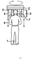
- FIG. 1 shows a dental X-ray diagnostic device with the device according to the invention in a side view
- FIG. 2 is a schematic diagram to explain the mechanical Relationships of the device
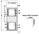
- FIG. 3 shows an embodiment of a detector arrangement
- FIGS. 4 and 5 show two versions of a detector arrangement
- FIG. 6 shows a schematic diagram for explaining transverse sections
- FIG. 7 shows a block diagram
- Figure 8 shows another embodiment of a detector arrangement.
- the device contains one in the Height adjustable support column 1, on which a rotating unit 2 is mounted, the Carrier on the one hand an X-ray source 3 and on the other hand diametrically for this purpose is an X-ray detector camera 4.
- a head restraint and Designated positioning device with which the Patient head can be fixed in a defined position. construction as well as adjustment options for the rotating unit and the head restraint and Positioning devices are known and for example in the beginning EP-0 632 994 mentioned.
- the line camera 4 consists of an elongated housing with an unspecified slot the side facing the radiation source.
- a detector arrangement 8 with one or more radiation sensitive detectors e.g. in the form of CCD sensors. Structure and arrangement will be explained in more detail later.
- the Detector arrangement 8 is inside the line detector camera in the direction its longitudinal axis adjustable in the direction of arrow 6. in the following is a detector arrangement with two active Detector elements out. This arrangement represents only one of several conceivable, within the scope of the invention Embodiments represent. In sync with this is also designated 7 Aperture system, which contains the primary aperture, is adjustable.
- the electromechanical connection of the line detector camera 4 with the Aperture system 7 is explained in more detail with reference to FIG. 2.
- Detector elements can be adjusted using a suitable here by means of a stepper motor 9 and a spin del 10, along the Detector main axis can be adjusted.
- the stepper motor 9 communicates via a (serial) interface 11 with control electronics 12 of the Device control of the X-ray device.
- the control electronics 12 passes another interface 13 control commands to one at the X-ray source 3 arranged actuator 14.
- Actuator is the synchronous adjustment of a primary diaphragm 15 of the Aperture system 7.
- the primary aperture 15 contains two spaced apart arranged diaphragm openings 16.
- the generated by the radiation source 3 X-rays are so divided into two beams 17, 17 ', so are focused on exactly two inside the line detector camera 4 arranged detectors 18, 18 'hit.
- the two detectors 18, 18 ' are arranged on a carrier 19 which, as described, by means of the Adjustment device 9, 10 is adjustable in the arrow direction indicated.
- FIG. 3 shows the detector arrangement in a front view.
- the carrier 19, on which the two detectors 18, 18 '9 are attached, is in one Frame 20 slidably supported.
- the clocking registers are 21 and 21 ' of the detectors referred to, as from the coordinate designation can be seen on the right in the picture, are designed as horizontal registers, i.e. the TDI direction (TDI stands for Time Delay and Integration and is one CCD-specific technology) runs perpendicular to the direction of displacement.
- TDI direction TDI stands for Time Delay and Integration and is one CCD-specific technology
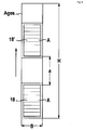
- FIG. 4 shows a single detector 18 with those for intraoral sensors usual dimensions. Such sensors typically have a height (h) of 30 mm and a width (b) of 20 mm. That of radiation Illuminated sensor area is labeled Ai and is in height (h ') 26 mm and in width (w') 18 mm.
- FIG. 5 shows a detector arrangement with several detectors.
- the for Object recording required detector area (Ages.) Is in n-areas subdivided, the partial area A the nth part of the total Detector area (Ages.) Corresponds.
- Each partial area is exposed m sensor surfaces (Ai) together, where m is the number of used Detectors re-presented. In the application example, two detectors 18, 18 'provided.
- detector and beam fan are each about 25 mm in Arrow direction, i.e. shifted along the longitudinal axis of the detectors. Around the specified total height of about 100 mm can therefore be achieved two recording phases necessary, a first in the shown Basic position and a second one, in which the two detectors by approx. 25 mm are shifted in the direction of the arrow.
- the operator first selects the recording parameters (examined Area, number, quality and size of the transverse sections and dose). These parameters can be on the X-ray machine or on a connected PC by selecting pre-defined programs or by manually compiling the parameters.
- the recording process is started. The device adjusts itself first by moving to reference points and positioning itself then in a starting position for the subsequent series of exposures.
- the number of individual shots results from the number of Transverse slice images and the number of acquisition phases. in the Embodiment of Figure 6 assume that the recorded arch 23 initially four different Layer images S1 to S4 of the left temporomandibular joint and then four further slice images S1 'to S4' of another jaw section should be created.
- the rotating unit 2 is first in the position P1 driven from which from the radiation source onto the desired imaging area can be delivered, the for example, should include the drawn angle ⁇ .
- the Layer image S1 is created by starting from a Starting position is blasted over the angle ⁇ . After the Recording for the layer S1 is created, the radiation source switched off and the turntable by the swivel angle ⁇ again moved back to the starting position. After that, the Layer layers S2, S3 and S4 created. Other layers for more Object sections can be created analogously, for example how shown from position P2.
- the kinematic movement sequence the receiving the radiation source and line detector camera Rotary unit is known per se, as is the control required for this the detectors according to the TDI procedure to achieve the desired stratification to obtain.
- the egg-ordinary Shot with radiation during the course of the turntable carried out.
- the radiation is switched off or it is rendered ineffective by adjusting the aperture.
- the first is a shift to be created completely, i.e. in a detector arrangement with two detectors initially two recording sequences with detector shift and the other layers S2, S3 accordingly and record S4.
- the detectors with a second read register (pos. 22, 22 ' in Fig. 3) to equip the TDI process in the opposite Direction.
- FIG. 7 shows a block diagram of the device according to the invention and clarifies the relationship between the individual components.
- the Device controller 12 generates control signals for the detector arrangement 8, the aperture system 7 and x-ray source 3 and coordinates for each Field sequence the sequence or the movement of the detector arrangement 8 and the emitter 3 corresponding to the predetermined path at one Admission.
- the image data acquired during the sequence are converted into one Buffer 25 stored.
- This 'raw image' is then in a further software 27 processed into an X-ray image, which is then stored in a database 28. From there it can accessed, for example, via a PC 29 and on a monitor 30 being represented. From the PC 29 can advantageously by the for one Necessary parameters are generated from the software 27, which are forwarded from there to the device control.
- the summation or Integration can - as shown - with the help of the CCD, which is TDI mode are described. This creates the picture during data acquisition by an 'analog' sum within the active CCD area.
- image acquisition is also possible without the TDI process, for each movement increment according to the necessary Sensor movement captures an image of the complete sensor area and is saved.
- the term is usually used for this operating mode 'full frame mode' or 'area mode' used.
- CCD technology instead of CCD technology with this alternative also to a cheaper technology (e.g. CMOS technology) can be used.
- CMOS technology e.g. CMOS technology
- the signals of a sub-picture generated with each recording become after Buffering from one signal processing software to one Layer image processed. Every transversal image is made up of the related recordings assembled by a computer, edited and saved and then displayed on a screen. At the The computer is composed of the geometric positions during the recording sequences and also the dimensions of the Detector known.
- the detector width should be at least 20 mm have to meet minimum depth of field requirements to be resolved transverse layer.
- This Recording sets can, as described, with the "analog” TDI procedures or "digital" summation can be created. To the To take transverse shift into account, these recording sets must can also be added up. For the summation of the digitized Recordings are understandably only the "digital" process sensibly applicable.
- the primary aperture setting is carried out synchronously with the Adjustment of the detectors. This can be done by a motor displaceable template in the manner shown in Figure 2. Alternatively, the cover can be adjusted accordingly a lower and upper delimitation; it is also conceivable a rotating bezel with at different locations Provide aperture openings.
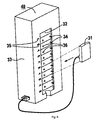
- Figure 8 shows a so-called 'dual-use' variant, in which a complete Intraoral sensor 31, as is known for intraoral recordings is used, also for the creation of transverse slice images can be used.
- a carrier 32 is provided which, like the Carrier 19 of the previously described embodiment, in the housing 33 of the Row detector camera 40 is arranged to be adjustable.
- the carrier 32 contains a variety of clamping or similar holding members 34 that it enable the sensor 31 to be held in different positions.
- holding elements 34 are arranged such that the sensor 31 can be held depending on the type of recording or recording area can.
- Lighten symbol markings 35 on the housing 33 the choice of the recording area or the type of recording. Instead of Symbols can also be used as a marker e.g. metric scaling be provided.
- the position of the sensor 31 used is determined by Position detector 36 detects. These can be electromechanical (Microswitch or the like) or optoelectric type (light barriers or the like.) The electrical connection and control takes place otherwise as described.
Landscapes
- Health & Medical Sciences (AREA)
- Life Sciences & Earth Sciences (AREA)
- Medical Informatics (AREA)
- Engineering & Computer Science (AREA)
- Physics & Mathematics (AREA)
- Pathology (AREA)
- Public Health (AREA)
- Biophysics (AREA)
- Nuclear Medicine, Radiotherapy & Molecular Imaging (AREA)
- Optics & Photonics (AREA)
- Veterinary Medicine (AREA)
- Radiology & Medical Imaging (AREA)
- Biomedical Technology (AREA)
- Heart & Thoracic Surgery (AREA)
- Molecular Biology (AREA)
- Surgery (AREA)
- Animal Behavior & Ethology (AREA)
- General Health & Medical Sciences (AREA)
- High Energy & Nuclear Physics (AREA)
- Mathematical Physics (AREA)
- Dentistry (AREA)
- Oral & Maxillofacial Surgery (AREA)
- Apparatus For Radiation Diagnosis (AREA)
Abstract
Description
Claims (10)
- Verfahren zur Erstellung von Röntgenaufnahmen in Form mehrerer Transversalschichtaufnahmen von Körperteilen eines Menschen, insbesondere von Röntgen-Schichtaufnahmen vom Kiefer oder Schädel eines Patienten, wobei ein von einer Strahlenquelle (3) erzeugtes und durch eine Blendenöffnung (16, 16') einer Primärblende (15) begrenztes Strahlenbündel nach Durchdringung des Aufnahmeobjekts auf eine Detektoranordnung (8) mit mindestens einem Detektor (18, 18') trifft, wobei die strahlungsempfindliche Fläche (Ai) des Detektors (18, 18') eine Teilfläche der zur Objektaufnahme erforderlichen Detektorfläche (Ages.) beträgt und wobei die Bildaufnahme in mehreren, zeitlich getrennten Abschnitten erfolgt, indem nach einer ersten Teilaufnahme die Detektoranordnung (8) in der Folge entlang der Längsachse und/oder Querachse der Detektorfläche verschoben wird und dazu die Blendenöffnung (16, 16') der Primärblende (15) entsprechend angepaßt wird, dadurch gekennzeichnet, dass eine Verschiebung der Detektoranordnung (8) erst dann erfolgt, wenn die Teilaufnahmen einer Detektorposition für alle gewünschten Schichtaufnahmen durchgeführt worden sind.
- Verfahren nach Anspruch 1, bei dem wobei zur Erzielung mehrerer Transversalschichtaufnahmen die Teilaufnahmen in einer Vorlaufphase und/oder in einer Rücklaufphase einer die Röntgenstrahlenquelle (3) und die Detektoranordnung (8) tragenden Dreheinheit (2) durchgeführt werden,
- Verfahren nach Anspruch 1 oder 2, bei dem als Detektor (18, 18') ein nach dem TDI-Verfahren betriebener CCD-Sensor verwendet wird.
- Verfahren nach Anspruch 1, bei dem als Detektor (18, 18') ein Bildaufnehmer verwendet wird, der eine Sequenz von rasch aufeinanderfolgenden Flächenaufnahmen erfaßt und bei dem die zur Bildentstehung notwendige Integration bzw. Summation in einer dem Bildaufnehmer nachgeschalteten Recheneinheit durchgeführt wird.
- Verfahren nach Anspruch 5, bei dem als Bildaufnehmer ein CCD-Sensor verwendet wird, der in der Betriebsart "full frame-mode" betrieben wird.
- CCD-Detektor zur Erstellung von Röntgenschichtaufnahmen nach dem Prinzip der Time Delay and Integration (TDI), umfassend ein als Horizontalregister ausgebildetes Austaktregister (21), wobei die TDI-Richtung quer zur Verschieberichtung des Detektors verläuft, dadurch gekennzeichnet, dass ein zweites Ausleseregister (22) vorgesehen ist und der verwendete Detektor (18; 31) in seiner Integrationsrichtung umschaltbar ausgebildet ist.
- Einrichtung zur Durchführung des Verfahrens nach einem der vorangegangenen Ansprüche, bei dem die zur Objektaufnahme er-forderliche Detektorfläche (Ages.) in n Flächen unterteilt ist, wobei die Teilfläche A dem n-ten Teil der gesamten De-tektorfläche (Ages.) entspricht und wobei jede Teilfläche sich aus m-Detektorflächen (Ai) zusammensetzt, wobei m die Anzahl der verwendeten Detektoren repräsentiert, gekennzeichnet durch einen CCD-Detektor nach Anspruch 6.
- Einrichtung zur Erstellung von Röntgenaufnahmen von Körperteilen eines Menschen, insbesondere von Röntgen-Schichtaufnahmen vom Kiefer oder Schädel eines Patienten,dadurch gekennzeichnet, daß ein einziger Detektor (31) in den Abmessungen eines Intraoralsensors verwendet ist und dass die zur Objektaufnahme erforderliche Detektorfläche (Ages.) in n Flächen unterteilt ist, wobei die Teilfläche (Ai) dem n-ten Teil der gesamten Detektorfläche (Ages.) entspricht und aus der einzigen Detektorfläche besteht, wobei ein Träger (32) mit mehreren Halteelementen (34) zur Halterung des Sensors (31) in verschiedenen Positionen vorhanden ist, und wobei jeder Position Positionsmelder (36) zugeordnet sind, die der Position des eingesetzten Sensors (31) entsprechende Signale an eine Steuereinrichtung (12) geben, wobei insbesondere ein Detektor gemäß Anspruch 6 verwendet wird.mit einer Strahlenquelle (3) zum Erzeugen eines Strahlbündels, der gegenüberliegend eine Detektoranordnung (8) mit einem Detektor (18,18') angeordnet ist,mit einer Primärblende (15) mit einer Blendenöffnung (16,16') zum Begrenzen des Strahlenbündels,mit einer Verstelleinrichtung, die die Detektoranordnung (8) entlang der Längsachse und/oder Querachse der Detektorfläche verschieben kann und dabei synchron die Blendenöffnung (16,16') der Primärblende verschieben kann,
- Einrichtung nach Anspruch 8, bei der die einzelnen Positionen zur Halterung des Sensors (31) im Träger (32) durch Markierungen (35) angezeigt sind.
- Einrichtung nach einem der Ansprüche 8 oder 9, bei der die Summation bzw. Integration der Teilaufnahmen entsprechend der Detektorebene und der gewünschten Schichtauflösung erfolgt.
Applications Claiming Priority (4)
| Application Number | Priority Date | Filing Date | Title |
|---|---|---|---|
| DE19706102 | 1997-02-17 | ||
| DE19706102 | 1997-02-17 | ||
| EP98102209A EP0858773B1 (de) | 1997-02-17 | 1998-02-09 | Vorrichtung zur Erstellung von Röntgenaufnahmen von Körperteilen eines Menschen |
| EP02006254A EP1219244B1 (de) | 1997-02-17 | 1998-02-09 | Verfahren und Einrichtung zur Herstellung von Röntgenaufnahmen von Körperteilen eines Menschen |
Related Parent Applications (1)
| Application Number | Title | Priority Date | Filing Date |
|---|---|---|---|
| EP02006254A Division EP1219244B1 (de) | 1997-02-17 | 1998-02-09 | Verfahren und Einrichtung zur Herstellung von Röntgenaufnahmen von Körperteilen eines Menschen |
Publications (3)
| Publication Number | Publication Date |
|---|---|
| EP1452137A2 true EP1452137A2 (de) | 2004-09-01 |
| EP1452137A3 EP1452137A3 (de) | 2004-09-08 |
| EP1452137B1 EP1452137B1 (de) | 2005-11-30 |
Family
ID=7820536
Family Applications (3)
| Application Number | Title | Priority Date | Filing Date |
|---|---|---|---|
| EP04102217A Expired - Lifetime EP1452137B1 (de) | 1997-02-17 | 1998-02-09 | Verfahren und Einrichtung zur Erstellung von Röntgenaufnahmen von Körperteilen eines Menschen |
| EP98102209A Expired - Lifetime EP0858773B1 (de) | 1997-02-17 | 1998-02-09 | Vorrichtung zur Erstellung von Röntgenaufnahmen von Körperteilen eines Menschen |
| EP02006254A Expired - Lifetime EP1219244B1 (de) | 1997-02-17 | 1998-02-09 | Verfahren und Einrichtung zur Herstellung von Röntgenaufnahmen von Körperteilen eines Menschen |
Family Applications After (2)
| Application Number | Title | Priority Date | Filing Date |
|---|---|---|---|
| EP98102209A Expired - Lifetime EP0858773B1 (de) | 1997-02-17 | 1998-02-09 | Vorrichtung zur Erstellung von Röntgenaufnahmen von Körperteilen eines Menschen |
| EP02006254A Expired - Lifetime EP1219244B1 (de) | 1997-02-17 | 1998-02-09 | Verfahren und Einrichtung zur Herstellung von Röntgenaufnahmen von Körperteilen eines Menschen |
Country Status (4)
| Country | Link |
|---|---|
| US (1) | US6055292A (de) |
| EP (3) | EP1452137B1 (de) |
| JP (1) | JPH10243944A (de) |
| DE (3) | DE59811970D1 (de) |
Cited By (2)
| Publication number | Priority date | Publication date | Assignee | Title |
|---|---|---|---|---|
| DE102006011004B4 (de) * | 2006-03-09 | 2008-12-04 | Siemens Ag | Röntgensystem mit Röntgen-Flachdetektoren |
| DE102008046723B4 (de) * | 2008-09-11 | 2011-05-12 | Siemens Aktiengesellschaft | Verfahren zum Betreiben einer Röntgendiagnostikeinrichtung sowie zugehörige Röntgendiagnostikeinrichtung |
Families Citing this family (27)
| Publication number | Priority date | Publication date | Assignee | Title |
|---|---|---|---|---|
| FI104943B (fi) * | 1998-06-26 | 2000-05-15 | Planmeca Oy | Menetelmä, laite ja niiden käyttö tomografiakuvantamisessa 2 |
| EP1219147B1 (de) | 1999-10-08 | 2006-11-08 | Gendex Corporation | Automatische belichtungssteuerung für ein zahnärztliches panorama- und schädelröntgengerät |
| WO2001058148A1 (en) | 2000-02-02 | 2001-08-09 | Dentsply International Inc. | Automatic x-ray detection for intra-oral dental x-ray imaging apparatus |
| FI120561B (fi) * | 2000-03-07 | 2009-11-30 | Planmeca Oy | Digitaalikamera, kuvantamislaite ja menetelmä digitaalisessa kuvantamisessa |
| DE10108298A1 (de) * | 2001-02-21 | 2002-09-26 | Sirona Dental Systems Gmbh | Anordnung und Verfahren zur Positionierung eines digitalen Röntgengerätes |
| DE10133657B4 (de) * | 2001-07-11 | 2008-12-24 | Siemens Ag | Verfahren zum Betrieb einer medizinischen Röntgeneinrichtung sowie medizinische Röntgeneinrichtung |
| JP2004536643A (ja) * | 2001-07-25 | 2004-12-09 | デンツプライ インターナショナル インコーポレーテッド | 実時間デジタルx線撮像装置 |
| US6823044B2 (en) * | 2001-11-21 | 2004-11-23 | Agilent Technologies, Inc. | System for collecting multiple x-ray image exposures of a sample using a sparse configuration |
| US7197109B2 (en) | 2002-07-25 | 2007-03-27 | Gendex Corporation | Real-time digital x-ray imaging apparatus |
| DE10313109A1 (de) * | 2003-03-24 | 2004-10-21 | Sirona Dental Systems Gmbh | Röntgenstrahlenempfindliche Kamera und Röntgeneinrichtung |
| DE10313110A1 (de) * | 2003-03-24 | 2004-10-21 | Sirona Dental Systems Gmbh | Röntgeneinrichtung und röntgenstrahlenempfindliche Kamera |
| JP3731207B2 (ja) * | 2003-09-17 | 2006-01-05 | 株式会社リガク | X線分析装置 |
| DE60318214T2 (de) * | 2003-11-21 | 2008-12-18 | Carestream Health, Inc., Rochester | Zahnärztliches Röntgengerät |
| US7130375B1 (en) * | 2004-01-14 | 2006-10-31 | Xradia, Inc. | High resolution direct-projection type x-ray microtomography system using synchrotron or laboratory-based x-ray source |
| JP2006013923A (ja) | 2004-06-25 | 2006-01-12 | Sony Corp | 監視装置 |
| JP4751130B2 (ja) * | 2005-08-16 | 2011-08-17 | パナソニック株式会社 | 画像処理装置 |
| DE102006021373A1 (de) | 2006-05-08 | 2007-11-15 | Siemens Ag | Röntgendiagnostikeinrichtung |
| KR101499267B1 (ko) * | 2007-01-24 | 2015-03-05 | 이미징 사이언시즈 인터내셔널 엘엘씨 | 치과 및 안면 촬상 장치 |
| KR100923097B1 (ko) * | 2008-01-15 | 2009-10-22 | (주)이우테크놀로지 | X선 촬영장치 |
| KR101577475B1 (ko) * | 2008-02-20 | 2015-12-14 | 이미징 사이언시즈 인터내셔널 엘엘씨 | 조정가능한 스캐너 |
| US20090274267A1 (en) * | 2008-04-30 | 2009-11-05 | Schick Technologies, Inc. | System and method for automatic jaw measurement for panoramic radiology |
| JP5247363B2 (ja) * | 2008-11-11 | 2013-07-24 | キヤノン株式会社 | X線撮影装置 |
| JP4516626B1 (ja) | 2009-09-28 | 2010-08-04 | 株式会社吉田製作所 | 歯科用x線撮影装置 |
| ITMI20120099A1 (it) | 2012-01-27 | 2013-07-28 | Gotzen S R L De | Apparato e metodo per radiografia digitale |
| KR20150088679A (ko) * | 2014-01-24 | 2015-08-03 | 주식회사바텍 | Ct 촬영 장치 |
| CN105741239B (zh) * | 2014-12-11 | 2018-11-30 | 合肥美亚光电技术股份有限公司 | 牙齿全景图像的生成方法、装置及用于拍摄牙齿的全景机 |
| JP2022534360A (ja) | 2019-05-30 | 2022-07-29 | ザ ユニバーシティ オブ ノース カロライナ アット チャペル ヒル | マルチモダリティ型歯科用x線イメージング装置および方法 |
Citations (3)
| Publication number | Priority date | Publication date | Assignee | Title |
|---|---|---|---|---|
| US4188537A (en) | 1976-10-15 | 1980-02-12 | Siemens Aktiengesellschaft | Dental apparatus for x-ray diagnosis |
| EP0229971A1 (de) | 1985-12-20 | 1987-07-29 | Siemens Aktiengesellschaft | Zahnärztliches Röntgendiagnostikgerät zur Erstellung von Panorama-Schichtaufnahmen vom Kiefer eines Patienten |
| EP0632994A1 (de) | 1993-07-06 | 1995-01-11 | Siemens Aktiengesellschaft | Röntgendiagnostikeinrichtung zur Erstellung von Röntgenaufnahmen von Körperteilen eines Patienten |
Family Cites Families (6)
| Publication number | Priority date | Publication date | Assignee | Title |
|---|---|---|---|---|
| NL8303156A (nl) * | 1983-09-13 | 1985-04-01 | Optische Ind De Oude Delft Nv | Roentgenopnameinrichting met spleetaftasting. |
| US4709382A (en) * | 1984-11-21 | 1987-11-24 | Picker International, Inc. | Imaging with focused curved radiation detectors |
| US4773087A (en) * | 1986-04-14 | 1988-09-20 | University Of Rochester | Quality of shadowgraphic x-ray images |
| DE9103670U1 (de) * | 1991-03-26 | 1991-05-29 | Transformatoren- und Röntgenwerk GmbH i.L., 01139 Dresden | Einrichtung zur Herstellung streustrahlenarmer Röntgenbilder |
| EP0632995B1 (de) * | 1993-07-06 | 1999-04-21 | Sirona Dental Systems GmbH & Co.KG | Zahnärztliche Röntgendiagnostikeinrichtung |
| JP3291406B2 (ja) * | 1995-02-09 | 2002-06-10 | 株式会社モリタ製作所 | パノラマx線撮影装置 |
-
1998
- 1998-02-09 EP EP04102217A patent/EP1452137B1/de not_active Expired - Lifetime
- 1998-02-09 DE DE59811970T patent/DE59811970D1/de not_active Expired - Fee Related
- 1998-02-09 EP EP98102209A patent/EP0858773B1/de not_active Expired - Lifetime
- 1998-02-09 DE DE59805461T patent/DE59805461D1/de not_active Expired - Lifetime
- 1998-02-09 DE DE59813247T patent/DE59813247D1/de not_active Expired - Fee Related
- 1998-02-09 EP EP02006254A patent/EP1219244B1/de not_active Expired - Lifetime
- 1998-02-16 JP JP10032772A patent/JPH10243944A/ja active Pending
- 1998-02-17 US US09/024,776 patent/US6055292A/en not_active Expired - Lifetime
Patent Citations (3)
| Publication number | Priority date | Publication date | Assignee | Title |
|---|---|---|---|---|
| US4188537A (en) | 1976-10-15 | 1980-02-12 | Siemens Aktiengesellschaft | Dental apparatus for x-ray diagnosis |
| EP0229971A1 (de) | 1985-12-20 | 1987-07-29 | Siemens Aktiengesellschaft | Zahnärztliches Röntgendiagnostikgerät zur Erstellung von Panorama-Schichtaufnahmen vom Kiefer eines Patienten |
| EP0632994A1 (de) | 1993-07-06 | 1995-01-11 | Siemens Aktiengesellschaft | Röntgendiagnostikeinrichtung zur Erstellung von Röntgenaufnahmen von Körperteilen eines Patienten |
Cited By (2)
| Publication number | Priority date | Publication date | Assignee | Title |
|---|---|---|---|---|
| DE102006011004B4 (de) * | 2006-03-09 | 2008-12-04 | Siemens Ag | Röntgensystem mit Röntgen-Flachdetektoren |
| DE102008046723B4 (de) * | 2008-09-11 | 2011-05-12 | Siemens Aktiengesellschaft | Verfahren zum Betreiben einer Röntgendiagnostikeinrichtung sowie zugehörige Röntgendiagnostikeinrichtung |
Also Published As
| Publication number | Publication date |
|---|---|
| EP0858773B1 (de) | 2002-09-11 |
| EP0858773A3 (de) | 1999-03-31 |
| DE59813247D1 (de) | 2006-01-05 |
| DE59805461D1 (de) | 2002-10-17 |
| US6055292A (en) | 2000-04-25 |
| EP1219244B1 (de) | 2004-09-15 |
| JPH10243944A (ja) | 1998-09-14 |
| EP1452137A3 (de) | 2004-09-08 |
| EP1219244A2 (de) | 2002-07-03 |
| EP1452137B1 (de) | 2005-11-30 |
| EP0858773A2 (de) | 1998-08-19 |
| DE59811970D1 (de) | 2004-10-21 |
| EP1219244A3 (de) | 2002-11-06 |
Similar Documents
| Publication | Publication Date | Title |
|---|---|---|
| EP1219244B1 (de) | Verfahren und Einrichtung zur Herstellung von Röntgenaufnahmen von Körperteilen eines Menschen | |
| EP1610685B2 (de) | Röntgeneinrichtung und röntgenstrahlenempfindliche Kamera für Panoramaschichtaufnahmen und 3d-Aufnahmen | |
| EP0632995B1 (de) | Zahnärztliche Röntgendiagnostikeinrichtung | |
| DE19754670B4 (de) | Mehrmodus-Panorma-Röntgengerät | |
| DE10206716B4 (de) | Verfahren zur Festlegung eines Zielbereichs einer CT-Röntgenbildaufnahmevorrichtung | |
| DE112006000869B4 (de) | Radiographievorrichtung mit Übersichtsbildfunktion | |
| DE10392506B4 (de) | Röntgen-CT-Gerät | |
| DE69433045T2 (de) | Computertomograph | |
| DE19941668B4 (de) | Verfahren und Vorrichtung zur computergestützen Röntgentomographie | |
| DE19733338C2 (de) | Röntgendiagnostikeinrichtung zur Erstellung von Panorama-Schichtaufnahmen von Körperteilen eines Patienten | |
| DE3703050C2 (de) | Verfahren zum Röntgen und Vorrichtung zur Durchführung des Verfahrens | |
| DE19910107A1 (de) | Computertomographie-Abtastvorrichtung | |
| EP2254475B1 (de) | Verfahren zur erstellung einer schichtaufnahme | |
| DE10354899B4 (de) | Röntgenvorrichtung und Verfahren zum Herstellen eines Röntgenbilddatensatzes | |
| DE19648076A1 (de) | Dentales Panorama-Röntgenabbildungsgerät | |
| WO2010012754A1 (de) | Verfahren zur erstellung einer dentalen 3d-röntgenaufnahme und röntgengerät hierfür | |
| DE10022468A1 (de) | Röntgen-CT-Vorrichtung | |
| DE112006002694T5 (de) | Medizinisches, digitales Röntgenbildgerät und medizinischer und digitaler Röntgenstrahlungssensor | |
| DE19738342A1 (de) | Verfahren und Vorrichtung zur Abtastung eines Objekts und Anzeige eines Bilds in einem Computer-Tomographie-System | |
| EP0993239B1 (de) | Röntgeneinrichtung | |
| DE3037478A1 (de) | Vorrichtung zur gleichzeitigen herstellung einer vielzahl von panoramaschichtaufnahmen der fokalkurve des zahnbogens | |
| DE10314536A1 (de) | Verfahren zur Erzeugung einer Röntgenaufnahme | |
| DE102005030285B4 (de) | Computertomographiegerät und Verfahren für ein Computertomographiegerät mit einem Markierungsmittel zur positionsgenauen Markierung einer Interventionsposition mittels eines Laser-strahls auf einem zu untersuchenden Objekt | |
| DE10234465A1 (de) | Verfahren zur Schichthöhenpositionierung | |
| EP1605828B1 (de) | Röntgengerät |
Legal Events
| Date | Code | Title | Description |
|---|---|---|---|
| PUAI | Public reference made under article 153(3) epc to a published international application that has entered the european phase |
Free format text: ORIGINAL CODE: 0009012 |
|
| PUAL | Search report despatched |
Free format text: ORIGINAL CODE: 0009013 |
|
| AC | Divisional application: reference to earlier application |
Ref document number: 0858773 Country of ref document: EP Kind code of ref document: P Ref document number: 1219244 Country of ref document: EP Kind code of ref document: P |
|
| AK | Designated contracting states |
Kind code of ref document: A2 Designated state(s): DE FI FR IT |
|
| AK | Designated contracting states |
Kind code of ref document: A3 Designated state(s): DE FI FR IT |
|
| RTI1 | Title (correction) |
Free format text: METHOD AND APPARATUS FOR PRODUCING X-RAY EXPOSURES OF HUMAN BODY PARTS |
|
| 17P | Request for examination filed |
Effective date: 20041221 |
|
| 17Q | First examination report despatched |
Effective date: 20050329 |
|
| AKX | Designation fees paid |
Designated state(s): DE FI FR IT |
|
| GRAP | Despatch of communication of intention to grant a patent |
Free format text: ORIGINAL CODE: EPIDOSNIGR1 |
|
| GRAS | Grant fee paid |
Free format text: ORIGINAL CODE: EPIDOSNIGR3 |
|
| GRAA | (expected) grant |
Free format text: ORIGINAL CODE: 0009210 |
|
| RTI1 | Title (correction) |
Free format text: METHOD AND APPARATUS FOR PRODUCING X-RAY EXPOSURES OF HUMAN BODY PARTS |
|
| AC | Divisional application: reference to earlier application |
Ref document number: 0858773 Country of ref document: EP Kind code of ref document: P Ref document number: 1219244 Country of ref document: EP Kind code of ref document: P |
|
| AK | Designated contracting states |
Kind code of ref document: B1 Designated state(s): DE FI FR IT |
|
| REF | Corresponds to: |
Ref document number: 59813247 Country of ref document: DE Date of ref document: 20060105 Kind code of ref document: P |
|
| ET | Fr: translation filed | ||
| PLBE | No opposition filed within time limit |
Free format text: ORIGINAL CODE: 0009261 |
|
| STAA | Information on the status of an ep patent application or granted ep patent |
Free format text: STATUS: NO OPPOSITION FILED WITHIN TIME LIMIT |
|
| 26N | No opposition filed |
Effective date: 20060831 |
|
| PGFP | Annual fee paid to national office [announced via postgrant information from national office to epo] |
Ref country code: DE Payment date: 20090227 Year of fee payment: 12 Ref country code: FI Payment date: 20090225 Year of fee payment: 12 |
|
| PGFP | Annual fee paid to national office [announced via postgrant information from national office to epo] |
Ref country code: IT Payment date: 20090219 Year of fee payment: 12 |
|
| PGFP | Annual fee paid to national office [announced via postgrant information from national office to epo] |
Ref country code: FR Payment date: 20090219 Year of fee payment: 12 |
|
| REG | Reference to a national code |
Ref country code: FR Ref legal event code: ST Effective date: 20101029 |
|
| PG25 | Lapsed in a contracting state [announced via postgrant information from national office to epo] |
Ref country code: FI Free format text: LAPSE BECAUSE OF NON-PAYMENT OF DUE FEES Effective date: 20100209 |
|
| PG25 | Lapsed in a contracting state [announced via postgrant information from national office to epo] |
Ref country code: FR Free format text: LAPSE BECAUSE OF NON-PAYMENT OF DUE FEES Effective date: 20100301 |
|
| PG25 | Lapsed in a contracting state [announced via postgrant information from national office to epo] |
Ref country code: DE Free format text: LAPSE BECAUSE OF NON-PAYMENT OF DUE FEES Effective date: 20100901 |
|
| PG25 | Lapsed in a contracting state [announced via postgrant information from national office to epo] |
Ref country code: IT Free format text: LAPSE BECAUSE OF NON-PAYMENT OF DUE FEES Effective date: 20100209 |