EP1452148B1 - Bracket - Google Patents
Bracket Download PDFInfo
- Publication number
- EP1452148B1 EP1452148B1 EP04003493A EP04003493A EP1452148B1 EP 1452148 B1 EP1452148 B1 EP 1452148B1 EP 04003493 A EP04003493 A EP 04003493A EP 04003493 A EP04003493 A EP 04003493A EP 1452148 B1 EP1452148 B1 EP 1452148B1
- Authority
- EP
- European Patent Office
- Prior art keywords
- closing spring
- slot
- tongue
- limb
- projections
- Prior art date
- Legal status (The legal status is an assumption and is not a legal conclusion. Google has not performed a legal analysis and makes no representation as to the accuracy of the status listed.)
- Expired - Lifetime
Links
- 239000000463 material Substances 0.000 claims description 7
- 238000011282 treatment Methods 0.000 claims description 6
- 238000003466 welding Methods 0.000 claims description 4
- 238000003780 insertion Methods 0.000 claims description 3
- 230000037431 insertion Effects 0.000 claims description 3
- 230000000149 penetrating effect Effects 0.000 claims description 3
- 238000005476 soldering Methods 0.000 claims description 3
- 238000005452 bending Methods 0.000 description 8
- 230000001965 increasing effect Effects 0.000 description 5
- 230000009471 action Effects 0.000 description 4
- 230000008901 benefit Effects 0.000 description 4
- 230000000694 effects Effects 0.000 description 4
- 238000004519 manufacturing process Methods 0.000 description 3
- 210000000332 tooth crown Anatomy 0.000 description 3
- 239000004568 cement Substances 0.000 description 2
- 239000002184 metal Substances 0.000 description 2
- 239000000853 adhesive Substances 0.000 description 1
- 230000001070 adhesive effect Effects 0.000 description 1
- 238000005266 casting Methods 0.000 description 1
- 238000010276 construction Methods 0.000 description 1
- 230000007423 decrease Effects 0.000 description 1
- 230000003028 elevating effect Effects 0.000 description 1
- 239000003292 glue Substances 0.000 description 1
- 230000012447 hatching Effects 0.000 description 1
- 230000003993 interaction Effects 0.000 description 1
- 230000001788 irregular Effects 0.000 description 1
- 238000000034 method Methods 0.000 description 1
- 238000003825 pressing Methods 0.000 description 1
- 230000008569 process Effects 0.000 description 1
- 210000005181 root of the tongue Anatomy 0.000 description 1
- 238000005507 spraying Methods 0.000 description 1
- 239000000725 suspension Substances 0.000 description 1
- 230000007704 transition Effects 0.000 description 1
Images




Classifications
-
- A—HUMAN NECESSITIES
- A61—MEDICAL OR VETERINARY SCIENCE; HYGIENE
- A61C—DENTISTRY; APPARATUS OR METHODS FOR ORAL OR DENTAL HYGIENE
- A61C7/00—Orthodontics, i.e. obtaining or maintaining the desired position of teeth, e.g. by straightening, evening, regulating, separating, or by correcting malocclusions
- A61C7/12—Brackets; Arch wires; Combinations thereof; Accessories therefor
- A61C7/28—Securing arch wire to bracket
- A61C7/30—Securing arch wire to bracket by resilient means; Dispensers therefor
-
- A—HUMAN NECESSITIES
- A61—MEDICAL OR VETERINARY SCIENCE; HYGIENE
- A61C—DENTISTRY; APPARATUS OR METHODS FOR ORAL OR DENTAL HYGIENE
- A61C7/00—Orthodontics, i.e. obtaining or maintaining the desired position of teeth, e.g. by straightening, evening, regulating, separating, or by correcting malocclusions
- A61C7/12—Brackets; Arch wires; Combinations thereof; Accessories therefor
- A61C7/28—Securing arch wire to bracket
-
- A—HUMAN NECESSITIES
- A61—MEDICAL OR VETERINARY SCIENCE; HYGIENE
- A61C—DENTISTRY; APPARATUS OR METHODS FOR ORAL OR DENTAL HYGIENE
- A61C7/00—Orthodontics, i.e. obtaining or maintaining the desired position of teeth, e.g. by straightening, evening, regulating, separating, or by correcting malocclusions
- A61C7/12—Brackets; Arch wires; Combinations thereof; Accessories therefor
- A61C7/28—Securing arch wire to bracket
- A61C7/287—Sliding locks
Definitions
- the invention relates to a bracket for orthodontic treatments, consisting of a base plate having a certain for attachment to a tooth bottom and a top on which a structure rises, having two spaced-apart wings, each of a elongated, both wings aligned flush penetrating slot are divided, the wings each divided into a gingival and an incisal section and is suitable for receiving a directional wire, and from a closing spring of a band-shaped material which is anchored to the structure, a on the gingival wing sections extending arc and a subsequent to the bow free leg and which is movable between an open position in which the slot is freely accessible in a region between the wing sections, and a closed position in which the free leg covers the slot.
- a bracket of this kind is for example off US 5 562 444 known.
- an extended leg is formed at the end remote from the slot of the arc of the closing spring, the free end is arranged in a wide throat, which is formed on the underside of the covered by the arc of the tongue gingival wing sections.
- This throat has a large opening angle which allows the closing spring to pivot about the gingival wing portions between open and closed positions, the apex of the throat forming a pivot bearing together with the free end of the throat portion of the closing spring.
- the spring adheres to the covered by her gingival wing sections by their inherent spring force by clamping action.
- bracket in which the spring has an extension at the end of the arch remote from the slot, which is forked into two legs received by channels extending laterally in the bracket assembly below the slot, transverse to this, run. Even with this bracket there is a risk of too great bending of the spring, because only one arc of about 180 ° arc length available for the bending when opening the spring.
- a bracket similar to the latter bracket is off US 4,492,573 known, having a substantially U-shaped closing spring, which can be moved to open the slot transverse to this in its entirety.
- US 4,144,642 describes a bracket with a bow spring, which can be moved to open and close the slot for receiving a directional wire across the slot.
- EP 1 287 789 A2 is a orthodontic bracket known, similar to that in the aforementioned US 5 562 444 is constructed.
- the closing spring on the bracket construction is not only pivotable but in its closed position additionally displaceable, comparable to the situation at US 4,492,573 , in which case the free spring end can slide under a projection formed on the incisal wing.
- US 5,685,711 describes a self-ligating orthodontic bracket, the closing spring has two legs substantially parallel to each other, of which in the closed position of one arranged in the wire receiving slot guide wire can press on the slot bottom and the other secures the closing spring by latching the bracket assembly in the closed position.
- the two legs of the closing spring are interconnected by a U-shaped arc, which forms the one part of a pivoting hinge, the other part of which is formed by two equiaxially opposed pins formed on the bracket assembly.
- the closing spring must be during manufacture of the bracket assembly which is composed of two mirror-image halves formed by laser welding to be attached to this, which not only requires a complicated manufacturing process, but also a subsequent replacement of the closing spring, such as if this should be damaged in use impossible.
- brackets have in common that their springs exert a force on a guide wire inserted in the slot, if any, which is directed towards the bottom of the slot, thus pressing the directional wire onto the slot bottom.
- the spring force is determined by the stiffness of the spring material and the effective spring length, which is relatively large in all examples, since it corresponds to the distance between the Einspannort the spring and the point of attack on the guide wire. Only when the spring stiffness is sufficiently large, the required closing force of the spring is generated, which in turn increases the risk of plastic bending of the spring when opening.
- a closing spring which presses the directional wire only to the bottom of the slot, is less suitable for achieving a torque which rotates a tooth provided with the bracket about an axis which is at the level of the crown of the tooth being treated.
- the invention has for its object to provide a bracket of the type mentioned, which is able to produce a high closing force for securing a directional wire in the slot slot, without increasing the risk of damage to the spring when opening.
- the bracket should also be able to provide high torque around an in To develop the height of a tooth crown lying axis.
- the covered by the arc of the closing spring gingival wing sections of the structure on the facing sides each have a projection
- the projections have free ends that face each other at a predetermined distance
- the free leg the closing spring in the central region has a tongue which is angled relative to adjacent lateral portions substantially at right angles to the top of the base plate
- the angled tongue has at least at its free end a width which is smaller than the distance of the opposing surfaces , which limit the space between the gingival wing sections, but otherwise is not wider than at their free end.
- tongue-shaped portion hereinafter referred to simply tongue
- adjacent lateral portions of the free end of the recoil spring are thus parallel resilient vanes which extend across the slot in the bracket assembly and are capable of securing a guidewire inserted therein in the slot ,
- the closing and securing action of the closing spring is determined almost exclusively by said tongue, the projections and the resilient lugs, and largely independent of the characteristics of the spring arch enclosing the gingival wing sections.
- the tongue may have at its free end a bent portion which engages in the closed state of the closing spring under said projections.
- the tongue has one on her. Root-setting neck region which is narrower than the mutual distance of the projections, and to the neck region is followed by a wider end portion whose width is greater than the mutual distance of the projections, but smaller than the distance of the side surfaces of the gingival wing sections. This wider end portion is in the closed state of the closing spring under the two projections and secures the closing spring against unintentional opening.
- a non-angled portion may be provided in the root area of the tongue be provided, which lies in the plane of the free leg of the closing spring, but this is defined on both sides in each case by a longitudinal incision.
- the closing spring preferably has an extension leg on an end of the arch facing away from the free leg, which is firmly anchored to the structure.
- a flat, structure permeating, through channel may be formed, and the extension leg of the spring, which is narrower than the arc, penetrates and abuts the channel its free end from the channel before, where it is bent over to secure the extension leg and thus the entire closing spring to the structure.
- a insertion slot may be formed, in which the extension leg is inserted and secured in the latter by welding, soldering or caulking.
- a hole adjacent to the tongue is formed in the closing spring.
- This hole is intended to receive a tool in the form of a needle, which is used to open and close the closing spring, inserted through the hole and with its help, the bent end of the tongue is released from its locking under the projections.
- incisal wing portions of the structure each have a shoulder formed on the in the closed position of the closing spring, the lateral portions of the free leg of the closing spring, i. the aforementioned resilient flags can rest.
- the closing spring When the closing spring is biased to the closed position, it can be secured in the open position by having the protrusions on the gingival wing portions each having an upper surface obliquely inclined from a crest edge in a direction extending away from the slit. In this inclined surface, the free end of the angled tongue can be supported in the open position of the closing spring. But the spring can also be designed so that it is biased under residual stress in an open position. It is by the bent end of the tongue, which engages under the projections on the gingival wing sections, against this bias in held the closed position.
- the bracket consists of a base plate 1, which has a bottom 2 (see Fig. 5 ) and a top 3, from which a structure rises, which is designated as a whole by 4.
- the base plate 1 has an irregular outline, because it is adapted to the contour of the crown of a tooth to which the bracket specifically shown here is to be attached.
- the assembly 4 has two mesially and distally spaced mesial and distal wings, generally designated 5 and 6, each divided into gingival and incisal sections 5a, 6a and 5b, 6b, respectively.
- the sections 5a and 5b are in Fig. 5 clearly distinguishable from one another by the example of the mesial blade 5 and separated from each other by a slot 7 extending between them, which is intended to receive a directional wire 8, examples of which are given in FIG FIGS. 5 to 7 are shown.
- Fig. 2 The space separating the mesial and distal wings 5 and 6 is in Fig. 2 designated 9 and extends to close over the top 3 of the base plate 1, see Figure 5 , In this space 9, two nose-shaped projections 10 extend from the gingival wing portions 5a and 6a starting towards each other.
- a flat slit is formed above the base plate 1, which extends in the central region of the structure 4 in this and which is intended to receive one end of a closing spring belonging to the bracket. Details will be explained later.
- the gingival wing sections 5a and 6a of the structure 4 are covered by an already mentioned closing spring, which is designated overall by 12.
- the closing spring 12 is available as a single part in Fig. 3 and 4 shown. It has an arc extending in several arcs section 13, at one, upper end, a free, largely straight end portion 14 connects and at the other, lower end is also a rectilinear extension 15 connects, which is narrower than the rest of the closing spring 12 is formed.
- the extension 15 is inserted into the slot 11 in the structure and secured therein by welding, soldering or caulking.
- the closing spring can be made of metal or plastic.
- the straight end portion 14 has in its central region on a tongue 17 which is disengaged on both sides of the material of the closing spring and bent in the direction of the base plate 1 of the bracket, such as Fig. 4 clearly shows.
- the tongue 17 is in the Fig. 5 shown closed position of the spring 12 is located so that it is adjacent to the slot 7. It has a bent-back end portion 17 a, which is deeper than the top 3 of the base plate 1 adjacent edge of the projections 10.
- the lateral, non-bent tabs 18 of the straight end portion 14 of the closing spring 12 cover the slot 7 and a directional wire inserted therein ( Fig. 5 ).
- the distance between a slot 7 laterally bounding wall and the adjacent projection 10 is at least as large as the thickness of the material of the closing spring 12th
- the closing spring 12 has a bore 20, which is intended for insertion of a pin-shaped tool, which may be formed, for example, similar to a crochet hook.
- the tongue 17 has a portion 17b in its root area, where the tongue 17 is connected to the free leg 14, on which is not angled relative to the free leg 14, but this is delimited on both sides by a longitudinal slot or notch 14a , Through these slots, the effective for the suspension of the tongue 17 length of Tongue increases, without changing the other dimensions of the closing spring 12 something. Increasing the effective tongue length helps prevent plastic bending or even breakage of the tongue 17 when inserting and changing a straightening wire. In addition, the effective lengths of the lugs 18, which form the free end of the closing spring 12, increased, which also counteracts a plastic bending.
- the basic structure of the bracket consisting of the base plate 1 and the structure 4, is preferably made in a casting or spraying of metal or a suitable plastic.
- the closing spring 12 is brought into position by inserting the extension 15 in the slot 11 and then secured therein in the manner already described.
- the underside 2 of the base plate 1 is intended to be attached to the crown of a tooth by means of an adhesive or cement.
- This glue or cement is in the FIGS. 5 to 7 represented by the reference numeral 21.
- FIGS. 6 and 7 can be seen in comparison with Fig. 5 the advantage of the invention.
- Fig. 5 is inserted into the slot 7 a directional wire 8 round cross-section, the Slot cross section does not fill.
- the flags 18 are largely without tension on the directional wire 8.
- Fig. 6 is inserted into the slot 7 a guidewire rectangular cross-section, which fills the slot in its full height.
- the lugs 18 bend slightly upwards when the closing spring is secured by locking the lower tongue end 17a under the projections 10 in the closed position.
- Fig. 7 is in the slot 7, a directional wire 8 rectangular cross-section inserted, which rises above the upper edge of the slot 7 addition. He has the consequence that the flags 18 are bent further upwards when the spring 12, as shown, is secured in the closed position.
- the rest of the closing spring remains completely unaffected by the nature of the securing state in the area of the slot.
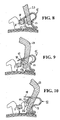
- Fig. 8 shows the bracket with inserted wire round cross-section (as an example) in one of Fig. 5 comparable condition.
- the bent-back end portion 17a of the notched tongue 17 of the closing spring 12 is below the bottom, so the base plate 1 near edge of the projections 10.
- the side lugs 18 of the closing spring 12 are on the directional wire 8.
- a pin-shaped tool 23 is inserted, which can be inserted between the projections 10. It touches the free edge of the bent end 17a of the tongue 17th
- the closing spring may have an effective bias in the opening direction. Supporting the tongue 17 on the projections 10 is then not mandatory. In any case, you can see from these two alternatives, that it does not depend on the directional wire 8 for the securing effect of the flags 18 and the tongue 17 on a certain bias of the closing spring, only the material constant and the dimensions in the range of flags 18, 17 is crucial and protrusions 10.
- FIG. 11 An alternative embodiment, which differs in two independent features from the previously shown and explained bracket is in Fig. 11 shown.
- this bracket joins at the upper end of the slot 7 on the incisal side of a shoulder on which the flags 18 can rest. Up to a directional wire cross-section, which does not completely fill the slot 7, therefore, do not press the tabs 18 onto the directional wire 8.
- the second deviating feature relates to the closing spring 12, which has at the lower end of the sheet 13 has an extension which is made so long that it completely penetrates a trained in Bracket inconvenience, formed transversely to the slot 7 flat channel 11 ', protrudes from this and secured there by bending the spring end.
- FIG. 11 shows the Fig. 11 in conjunction with the FIGS. 12 and 13
- a bias of the closing spring as an instrument for applying straightening forces on a wire.
- FIGS. 11 to 13 show the bracket of the invention when used with a directional wire 8 rectangular cross-section.
- Directional wires with rectangular cross section are used towards the end of an orthodontic treatment with brackets, when the tooth misalignment has already been corrected due to the progress of the orthodontic treatment to the extent that straightening wires of smaller cross section, in particular round cross section, are no longer able to those torques on the teeth which are necessary to bring the teeth in the desired end position.
- brackets for example, an upper jaw
- the straightening wire passes through the slots of all the brackets. Its position within the bracket slots is therefore determined not only by the individual bracket, but by the interaction of all brackets, which in turn is determined by the position of all the teeth in the row of teeth in question.
- the teeth are thus aligned by the forces acting on the directional wire mutually opposing forces.
- Fig. 11 is due to the misalignment of the provided with the bracket shown (not shown) tooth of the directional wire 8 in the slot 17 is tilted so that between the outer surfaces of the directional wire 8 and the slot 7 limiting surfaces arise wedge-shaped spaces.
- the closing spring 12 exercises with the side lugs 18 and the tongue 17 on the directional wire 8 forces that want to press him on the bottom of the slot 7 and in abutment against the tongue 17 opposite slot wall. These forces cause the overall torque on the bracket to be exerted on the bracket Fig. 11 with the arrows T is shown.
- FIGS. 14 and 15 show a particularly advantageous embodiment of the invention.
- the tongue 17 a at the tongue root attaching neck portion 17c which has a width which is smaller than the distance between the projections 10 at the gingival wing portions 5a, 6a.
- the neck portion 17c is followed by a widened end portion 17d whose width is greater than the spacing of the projections 10 from each other, but smaller than the distance of the gingival wing portions 5a, 6a from each other.
- the tongue 17 is flat and is a notched from the free leg 14 of the closing spring 12 in the forward and downward direction, so that in the free leg 14 a T-shaped opening 14 b remains.
- the widened end portion 17 d of the tongue can be supported in the open state of the closing spring 12 on the two projections 10 and so hold the closing spring 12 in its open position.
- the neck portion 17c slides between the two projections 10 so that the wide end portion 17d engages under the projections 10 and locks the closing spring 12 in its closed position.
- the orthodontist can press the tongue 17 out of its locking position to a suitable pin-shaped tool to open the closing spring 12.
- the particular advantage of this embodiment lies in the smaller number of bending operations that are required for the production of the closing spring.
- the distance between the projections and the bracket slot can be minimized. It only has to be as big as the spring thickness, a spring curvature need not be taken into account.
- the security function is improved because the wide tongue portion is below the projections.
- the wider end portion 17d of the tongue 17 may be provided with a bent end portion also in the manner of the tongue of the first-mentioned embodiments. It should also be noted that in the embodiment according to the FIGS. 14 and 15 the tongue 17 can be unlatched and angled out of the free leg 14 of the closing spring 12, as for the first-mentioned embodiments above based on Fig. 4 was shown and described.
Landscapes
- Health & Medical Sciences (AREA)
- Oral & Maxillofacial Surgery (AREA)
- Dentistry (AREA)
- Epidemiology (AREA)
- Life Sciences & Earth Sciences (AREA)
- Animal Behavior & Ethology (AREA)
- General Health & Medical Sciences (AREA)
- Public Health (AREA)
- Veterinary Medicine (AREA)
- Dental Tools And Instruments Or Auxiliary Dental Instruments (AREA)
Claims (12)
- Bracket pour traitement orthopédique de la mâchoire, constitué :d'une plaque de base (1) qui présente une face inférieure (2) destinée à la fixation sur une dent et une face supérieure (3), sur laquelle s'élève un montage (4) qui comporte deux ailettes (5, 6), disposées à distance mutuelle et respectivement interrompues par une fente (7) allongée, qui traverse en alignement les deux ailettes (5, 6), laquelle fente subdivise chacune des ailettes (5, 6) en une section gingivale et en une section incisive (5a, 6a ; 5b, 6b) et se prête au logement d'un fil redresseur, etd'un ressort de fermeture (12) en un matériau en forme de bande, qui est ancré sur le montage (4), présente un arc (13) s'étendant sur les sections d'ailettes gingivales (5a, 6a), ainsi qu'une branche libre (14) se raccordant à l'arc (13), et est mobile entre une position d'ouverture, dans laquelle la fente (7) entre les sections d'ailettes (5a, 5b ; 6a, 6b) est librement accessible, et une position de fermeture, dans laquelle la branche libre (14) recouvre la fente (7),
caractérisé en ce queles sections d'ailettes gingivales (5a, 6a) du montage (4), recouvertes par l'arc (13) du ressort de fermeture (12), présentent chacune sur les côtés tournés l'un vers l'autre une saillie (10),les saillies (10) ont des extrémités libres, qui se situent en vis-à-vis à une distance prédéfinie,la branche libre (14) du ressort de fermeture (12) présente dans la zone centrale une languette (17), qui est coudée par rapport à des sections latérales voisines (18) essentiellement en angle droit en direction de la face supérieure (3) de la plaque de base (1),la languette coudée (17) a au moins sur son extrémité libre une largeur, qui est plus petite que la distance des surfaces en vis-à-vis mutuel délimitant l'espace intermédiaire (9) entre les sections d'ailettes gingivales (5a, 6a), et plus grande que la distance entre les extrémités libres des saillies (10), mais au demeurant pas plus large que sur son extrémité libre. - Bracket suivant la revendication 1, caractérisé en ce que la languette coudée (17) présente une section extrême (17a), qui est pliée en direction de l'arc (13) du ressort de fermeture (12) et est plus basse, en position de fermeture du ressort (12), qu'une arête inférieure des saillies (10) citées.
- Bracket suivant l'une des revendications 1 et 2, caractérisé en ce que la languette (17) présente dans la zone de sa racine une section (17b) non coudée, qui est délimitée bilatéralement, par rapport à la branche libre (14) du ressort de fermeture (12), par une entaille (14a) longitudinale.
- Bracket suivant la revendication 1, caractérisé en ce que la languette coudée (17) présente à partir de sa racine une section de col (17c), qui est plus étroite que la distance entre les extrémités libres des saillies (10) et à laquelle se raccorde une section extrême plus large (17d), qui se situe au-dessous des saillies (10) dans l'état de fermeture du ressort de fermeture (12).
- Bracket suivant l'une des revendications précédentes, caractérisé en ce qu'un trou (20) est réalisé dans le ressort de fermeture (12) au voisinage de la section centrale coudée (17) de la branche libre (14).
- Bracket suivant l'une des revendications 1 à 4, caractérisé en ce que la languette (17) est configurée sous forme d'une section du ressort de fermeture (12), encochée vers l'arrière sur la branche libre (14) du ressort de fermeture (12) et laissant une ouverture (14b) dans la branche libre (14).
- Bracket suivant l'une des revendications précédentes, caractérisé en ce que le ressort de fermeture (12) présente, sur une extrémité de l'arc (13) opposée à la branche libre (14), une branche de prolongement (15) qui est ancrée solidementsur le montage (4).
- Bracket suivant la revendication 7, caractérisé en ce qu'un canal continu plat (11), traversant le montage (4), est réalisé dans le montage (4) au-dessus de la face supérieure (3) de la plaque de base (1), mais au-dessous de la fente (7), la branche de prolongement (15) du ressort de fermeture (12) a une configuration plus étroite que l'arc (13) et est disposée dans le canal (11), et que la branche de prolongement (15) présente une extrémité libre (16), qui est pliée et dépasse du canal (11) pour bloquer la branche de prolongement (15) dans le canal (11).
- Bracket suivant la revendication 7, caractérisé en ce qu'une fente d'emboîtement (11a) est réalisée sur le montage (4) au-dessous des sections d'ailettes gingivales (5a, 6a) recouvertes par l'arc (13) du ressort de fermeture (12), fente dans laquelle est emmanchée la branche de prolongement (15') et dans laquelle la branche de prolongement (15') est bloquée par soudage, brasage ou matage.
- Bracket suivant l'une des revendications précédentes, caractérisé en ce qu'un épaulement (19) est respectivement réalisé sur les sections d'ailettes incisives (5b, 6b) du montage (4), au voisinage de la fente (7), épaulements sur lesquels s'appliquent deux sections extrêmes latérales (18), non pliées, du ressort de fermeture (12) dans la position de fermeture de ce dernier.
- Bracket suivant l'une des revendications précédentes, caractérisé en ce que les saillies (10) présentent chacune une face supérieure (22), qui est inclinée en oblique à partir d'une arête de sommet dans une direction s'étendant à l'écart de la fente (7).
- Bracket suivant l'une des revendications précédentes, caractérisé en ce qu'un écartement libre est présent entre les saillies (10) et la fente (7)., lequel écartement est au moins aussi élevé qu'une épaisseur de matériau du ressort de fermeture (12).
Applications Claiming Priority (4)
| Application Number | Priority Date | Filing Date | Title |
|---|---|---|---|
| DE10308795 | 2003-02-27 | ||
| DE10308795 | 2003-02-27 | ||
| DE10324088A DE10324088A1 (de) | 2003-02-27 | 2003-05-27 | Bracket |
| DE10324088 | 2003-05-27 |
Publications (3)
| Publication Number | Publication Date |
|---|---|
| EP1452148A2 EP1452148A2 (fr) | 2004-09-01 |
| EP1452148A3 EP1452148A3 (fr) | 2007-06-06 |
| EP1452148B1 true EP1452148B1 (fr) | 2009-04-15 |
Family
ID=32773173
Family Applications (1)
| Application Number | Title | Priority Date | Filing Date |
|---|---|---|---|
| EP04003493A Expired - Lifetime EP1452148B1 (fr) | 2003-02-27 | 2004-02-17 | Bracket |
Country Status (4)
| Country | Link |
|---|---|
| US (1) | US6942483B2 (fr) |
| EP (1) | EP1452148B1 (fr) |
| JP (1) | JP4467330B2 (fr) |
| CA (1) | CA2458757A1 (fr) |
Families Citing this family (31)
| Publication number | Priority date | Publication date | Assignee | Title |
|---|---|---|---|---|
| US7063531B2 (en) * | 2004-07-16 | 2006-06-20 | Rolf Maijer | Orthodontic bracket system |
| US7267545B2 (en) | 2005-01-11 | 2007-09-11 | Ormco Corporation | Self-ligating orthodontic bracket |
| US7214057B2 (en) | 2005-03-10 | 2007-05-08 | Ceramic Sciences Incorporated | Self-ligating orthodontic bracket |
| EP1942823A4 (fr) * | 2005-09-28 | 2012-02-29 | American Orthodontics Corp | Systeme de bracket autoligaturant |
| US7704072B2 (en) | 2006-04-19 | 2010-04-27 | Ormco Corporation | Orthodontic bracket |
| US20070269763A1 (en) * | 2006-05-18 | 2007-11-22 | Claus Schendell-Groling | Orthodontic bracket |
| ITFI20070069A1 (it) * | 2007-03-22 | 2008-09-23 | Leone Spa | Attacco ortodontico |
| US20090017413A1 (en) * | 2007-06-19 | 2009-01-15 | Patrick Roman | Orthodontic bracket assembly |
| EP2008611A1 (fr) * | 2007-06-28 | 2008-12-31 | Ormco Corporation | Outils à main orthodontiques pour une utilisation avec un support orthodontique à ligature automatique, procédés pour l'utilisation de tels outils à main orthodontiques et supports orthodontiques à ligature automatique et systèmes de supports orthodontiques |
| US20110143301A1 (en) * | 2007-08-17 | 2011-06-16 | Rolf Maijer | Single continuous spring orthodontic bracket and system |
| DE102007062735B3 (de) | 2007-12-27 | 2009-07-09 | Heiser, Wolfgang, Dr. med. habi. | Selbstligierendes kieferorthopädisches Bracket |
| US8246348B2 (en) | 2007-12-27 | 2012-08-21 | Wolfgang Heiser | Self-ligating orthodontic bracket |
| JP2012515067A (ja) * | 2009-01-16 | 2012-07-05 | オルムコ コーポレイション | 転位歯を矯正する歯科矯正ブラケットおよび方法 |
| FI121776B (fi) | 2009-03-10 | 2011-04-15 | Tuomo Kantomaa | Hammaskiinnike ja järjestely hampaiden oikomiseksi |
| US8636507B2 (en) * | 2009-06-03 | 2014-01-28 | John C. Voudouris | Self-ligating orthodontic bracket |
| US8162660B2 (en) | 2009-11-20 | 2012-04-24 | Robert T Rudman | Rotating clip orthodontic bracket |
| US9345558B2 (en) | 2010-09-03 | 2016-05-24 | Ormco Corporation | Self-ligating orthodontic bracket and method of making same |
| US9615897B2 (en) | 2010-09-10 | 2017-04-11 | Ormco Corporation | Self-ligating orthodontic bracket |
| US10321978B2 (en) | 2010-09-17 | 2019-06-18 | Tomy Incorporated | Orthodontic bracket |
| JP5154715B2 (ja) * | 2010-09-17 | 2013-02-27 | トミー株式会社 | 歯列矯正ブラケット |
| EP2783656B1 (fr) | 2013-03-15 | 2017-06-28 | American Orthodontics Corporation | Support actif à ligature automatique |
| RU2664158C2 (ru) | 2013-06-14 | 2018-08-15 | Ормко Корпорейшн | Самолигирующийся ортодонтический брекет с поворотным запирающим элементом |
| US9049905B2 (en) * | 2013-10-23 | 2015-06-09 | GM Global Technology Operations LLC | Clip and coupling assembly |
| CN106659546A (zh) | 2014-07-09 | 2017-05-10 | 3M创新有限公司 | 具有正向旋转锁定件的自锁正畸托槽 |
| US10111731B2 (en) | 2014-11-18 | 2018-10-30 | American Orthodontics Corporation | Self-ligating bracket |
| CA2976417A1 (fr) * | 2015-02-06 | 2016-08-11 | Orthoarm, Inc. | Boitier orthodontique a profil bas |
| CN107847294A (zh) * | 2015-06-08 | 2018-03-27 | 美国正畸公司 | 自锁托架 |
| US9770310B2 (en) * | 2016-02-25 | 2017-09-26 | Pbd, Patent & Business Development Ag | Orthodontic self-ligating bracket |
| CN213787904U (zh) * | 2020-11-23 | 2021-07-27 | 杭州朋武医疗器械有限公司 | 一种用于牙齿矫正的主动自锁托槽 |
| US12350123B2 (en) * | 2020-12-23 | 2025-07-08 | Hirsch Dynamics Holding Ag | Self-ligating orthodontic bracket |
| CN113974870B (zh) * | 2021-10-13 | 2023-03-07 | 北京大学口腔医学院 | Nance弓正畸磨牙控制装置 |
Family Cites Families (8)
| Publication number | Priority date | Publication date | Assignee | Title |
|---|---|---|---|---|
| US4023274A (en) * | 1975-06-02 | 1977-05-17 | Melvin Wallshein | Orthodontic spring clip |
| US4144642A (en) | 1976-07-26 | 1979-03-20 | Melvin Wallshein | Retainer members for orthodontic brackets |
| US4492573A (en) | 1984-03-27 | 1985-01-08 | Augusta Developments Inc. | Orthodontic bracket |
| US4712999A (en) * | 1986-09-10 | 1987-12-15 | Farel Rosenberg | Convertible, self-ligating, archwire positioning orthodontic bracket |
| DE4407100C2 (de) | 1994-03-03 | 1997-11-13 | Wolfgang Dr Med Heiser | Bracket für kieferorthopädische Behandlungen |
| US5685711A (en) * | 1995-12-06 | 1997-11-11 | Hanson; G. Herbert | Self-ligating orthodontic brackets |
| US5711666A (en) * | 1996-10-22 | 1998-01-27 | Hanson; G. Herbert | Self-ligating orthodontic brackets |
| JP4411573B2 (ja) * | 2001-08-24 | 2010-02-10 | トミー株式会社 | 歯列矯正ブラケット |
-
2004
- 2004-02-17 EP EP04003493A patent/EP1452148B1/fr not_active Expired - Lifetime
- 2004-02-23 CA CA002458757A patent/CA2458757A1/fr not_active Abandoned
- 2004-02-25 JP JP2004049259A patent/JP4467330B2/ja not_active Expired - Fee Related
- 2004-02-26 US US10/788,101 patent/US6942483B2/en not_active Expired - Fee Related
Also Published As
| Publication number | Publication date |
|---|---|
| EP1452148A3 (fr) | 2007-06-06 |
| JP2004255190A (ja) | 2004-09-16 |
| EP1452148A2 (fr) | 2004-09-01 |
| US6942483B2 (en) | 2005-09-13 |
| US20040170942A1 (en) | 2004-09-02 |
| CA2458757A1 (fr) | 2004-08-27 |
| JP4467330B2 (ja) | 2010-05-26 |
Similar Documents
| Publication | Publication Date | Title |
|---|---|---|
| EP1452148A2 (fr) | Bracket | |
| DE102007062735B3 (de) | Selbstligierendes kieferorthopädisches Bracket | |
| EP0938874B1 (fr) | Bracket orthodontique | |
| DE3341259C2 (de) | Orthodonte Klammer | |
| DE60130705T2 (de) | Kabelklemme | |
| DE102006027130B4 (de) | Selbstligierendes Bracket und dessen Verwendung für die Orthodontie | |
| EP0033132B1 (fr) | Serre-câble | |
| DE1944511A1 (de) | Kabelbinder | |
| CH701510A2 (de) | Selbstligierendes Bracket und darin aufzunehmender Drahtbogen. | |
| DE4407100A1 (de) | Bracket für kieferorthopädische Behandlungen | |
| DE68921188T2 (de) | Orthodontische Vorrichtung. | |
| DE3324389C2 (fr) | ||
| EP1641408A1 (fr) | Appareil orthodontique | |
| CH648201A5 (de) | Dentalsplint. | |
| CH660297A5 (de) | Extraktionsinstrument fuer wundklammern. | |
| WO2008116817A1 (fr) | Dispositif de fixation et outil de verrouillage d'un élément de fixation | |
| DE112016005848T5 (de) | Kieferorthopädische Klammer | |
| EP0698720A1 (fr) | Procédé de fixation d'équerres d'assemblage, de prérérence en matière plastique soudable, ainsi qu'équerres y afférant | |
| AT662U1 (de) | Einrichtung zur befestigung einer haltemechanik | |
| WO2010089065A1 (fr) | Dispositif de serrage | |
| EP1629790A1 (fr) | Appareil orthodontique pour corriger les positions dentaires et bracket utilisé dans cet appareil | |
| EP4279699A1 (fr) | Connecteur à fiche | |
| EP3422994B1 (fr) | Attache orthodontique | |
| DE102023123151A1 (de) | Leiteranschlussklemme | |
| DE29921227U1 (de) | Linearverbinder aus Kunststoff für Abstandhalterrahmen von Mehrscheibenisoliergläsern |
Legal Events
| Date | Code | Title | Description |
|---|---|---|---|
| PUAI | Public reference made under article 153(3) epc to a published international application that has entered the european phase |
Free format text: ORIGINAL CODE: 0009012 |
|
| AK | Designated contracting states |
Kind code of ref document: A2 Designated state(s): AT BE BG CH CY CZ DE DK EE ES FI FR GB GR HU IE IT LI LU MC NL PT RO SE SI SK TR |
|
| AX | Request for extension of the european patent |
Extension state: AL LT LV MK |
|
| PUAL | Search report despatched |
Free format text: ORIGINAL CODE: 0009013 |
|
| AK | Designated contracting states |
Kind code of ref document: A3 Designated state(s): AT BE BG CH CY CZ DE DK EE ES FI FR GB GR HU IE IT LI LU MC NL PT RO SE SI SK TR |
|
| AX | Request for extension of the european patent |
Extension state: AL LT LV MK |
|
| 17P | Request for examination filed |
Effective date: 20071203 |
|
| AKX | Designation fees paid |
Designated state(s): DE GB |
|
| GRAP | Despatch of communication of intention to grant a patent |
Free format text: ORIGINAL CODE: EPIDOSNIGR1 |
|
| GRAS | Grant fee paid |
Free format text: ORIGINAL CODE: EPIDOSNIGR3 |
|
| GRAA | (expected) grant |
Free format text: ORIGINAL CODE: 0009210 |
|
| AK | Designated contracting states |
Kind code of ref document: B1 Designated state(s): DE GB |
|
| REG | Reference to a national code |
Ref country code: GB Ref legal event code: FG4D Free format text: NOT ENGLISH |
|
| REF | Corresponds to: |
Ref document number: 502004009339 Country of ref document: DE Date of ref document: 20090528 Kind code of ref document: P |
|
| PLBE | No opposition filed within time limit |
Free format text: ORIGINAL CODE: 0009261 |
|
| STAA | Information on the status of an ep patent application or granted ep patent |
Free format text: STATUS: NO OPPOSITION FILED WITHIN TIME LIMIT |
|
| 26N | No opposition filed |
Effective date: 20100118 |
|
| GBPC | Gb: european patent ceased through non-payment of renewal fee |
Effective date: 20100217 |
|
| PG25 | Lapsed in a contracting state [announced via postgrant information from national office to epo] |
Ref country code: GB Free format text: LAPSE BECAUSE OF NON-PAYMENT OF DUE FEES Effective date: 20100217 |
|
| PGFP | Annual fee paid to national office [announced via postgrant information from national office to epo] |
Ref country code: DE Payment date: 20150225 Year of fee payment: 12 |
|
| REG | Reference to a national code |
Ref country code: DE Ref legal event code: R119 Ref document number: 502004009339 Country of ref document: DE |
|
| PG25 | Lapsed in a contracting state [announced via postgrant information from national office to epo] |
Ref country code: DE Free format text: LAPSE BECAUSE OF NON-PAYMENT OF DUE FEES Effective date: 20160901 |