EP1452149A1 - Zusammenbau eines Zahnimplantates und eines Abutments, sowie Verfahren zum Verbinden des Abutments mit dem Implantat - Google Patents
Zusammenbau eines Zahnimplantates und eines Abutments, sowie Verfahren zum Verbinden des Abutments mit dem Implantat Download PDFInfo
- Publication number
- EP1452149A1 EP1452149A1 EP03078950A EP03078950A EP1452149A1 EP 1452149 A1 EP1452149 A1 EP 1452149A1 EP 03078950 A EP03078950 A EP 03078950A EP 03078950 A EP03078950 A EP 03078950A EP 1452149 A1 EP1452149 A1 EP 1452149A1
- Authority
- EP
- European Patent Office
- Prior art keywords
- implant
- abutment
- pin
- hole
- adapter ring
- Prior art date
- Legal status (The legal status is an assumption and is not a legal conclusion. Google has not performed a legal analysis and makes no representation as to the accuracy of the status listed.)
- Withdrawn
Links
- 239000007943 implant Substances 0.000 title claims abstract description 82
- 239000004053 dental implant Substances 0.000 title claims abstract description 5
- 238000000034 method Methods 0.000 title claims description 4
- 239000004568 cement Substances 0.000 claims abstract description 17
- 230000007704 transition Effects 0.000 description 5
- 239000000853 adhesive Substances 0.000 description 2
- 230000001070 adhesive effect Effects 0.000 description 2
- 230000003247 decreasing effect Effects 0.000 description 2
- 239000000463 material Substances 0.000 description 2
- 239000000919 ceramic Substances 0.000 description 1
- 230000001055 chewing effect Effects 0.000 description 1
- 238000005553 drilling Methods 0.000 description 1
- 238000003754 machining Methods 0.000 description 1
- 238000004519 manufacturing process Methods 0.000 description 1
- 238000012986 modification Methods 0.000 description 1
- 230000004048 modification Effects 0.000 description 1
- 239000012858 resilient material Substances 0.000 description 1
- 239000007787 solid Substances 0.000 description 1
- 230000003313 weakening effect Effects 0.000 description 1
Images
Classifications
-
- A—HUMAN NECESSITIES
- A61—MEDICAL OR VETERINARY SCIENCE; HYGIENE
- A61C—DENTISTRY; APPARATUS OR METHODS FOR ORAL OR DENTAL HYGIENE
- A61C8/00—Means to be fixed to the jaw-bone for consolidating natural teeth or for fixing dental prostheses thereon; Dental implants; Implanting tools
- A61C8/0048—Connecting the upper structure to the implant, e.g. bridging bars
- A61C8/005—Connecting devices for joining an upper structure with an implant member, e.g. spacers
-
- A—HUMAN NECESSITIES
- A61—MEDICAL OR VETERINARY SCIENCE; HYGIENE
- A61C—DENTISTRY; APPARATUS OR METHODS FOR ORAL OR DENTAL HYGIENE
- A61C8/00—Means to be fixed to the jaw-bone for consolidating natural teeth or for fixing dental prostheses thereon; Dental implants; Implanting tools
- A61C8/0048—Connecting the upper structure to the implant, e.g. bridging bars
- A61C8/005—Connecting devices for joining an upper structure with an implant member, e.g. spacers
- A61C8/0065—Connecting devices for joining an upper structure with an implant member, e.g. spacers with expandable or compressible means
-
- A—HUMAN NECESSITIES
- A61—MEDICAL OR VETERINARY SCIENCE; HYGIENE
- A61C—DENTISTRY; APPARATUS OR METHODS FOR ORAL OR DENTAL HYGIENE
- A61C8/00—Means to be fixed to the jaw-bone for consolidating natural teeth or for fixing dental prostheses thereon; Dental implants; Implanting tools
- A61C8/0048—Connecting the upper structure to the implant, e.g. bridging bars
- A61C8/005—Connecting devices for joining an upper structure with an implant member, e.g. spacers
- A61C8/0059—Connecting devices for joining an upper structure with an implant member, e.g. spacers with additional friction enhancing means
-
- A—HUMAN NECESSITIES
- A61—MEDICAL OR VETERINARY SCIENCE; HYGIENE
- A61C—DENTISTRY; APPARATUS OR METHODS FOR ORAL OR DENTAL HYGIENE
- A61C8/00—Means to be fixed to the jaw-bone for consolidating natural teeth or for fixing dental prostheses thereon; Dental implants; Implanting tools
- A61C8/0048—Connecting the upper structure to the implant, e.g. bridging bars
- A61C8/005—Connecting devices for joining an upper structure with an implant member, e.g. spacers
- A61C8/006—Connecting devices for joining an upper structure with an implant member, e.g. spacers with polygonal positional means, e.g. hexagonal or octagonal
Definitions
- the invention relates to an assembly of a dental implant and an abutment, said implant being provided with external means for fixing said implant into a jaw bone and with an internal hole for receiving a pin of the abutment, as described in the preamble of claim 1.
- US 5 839 898 describes an abutment which is primary shaped of two separate parts. From one surface of the engaging surfaces material can be removed so that the parts will make an angle with each other after having been connected to each other. By this it is obtained that the place of the retainer for a dental implant can be adjusted. By means of said primary shaped abutment the final abutment can be fabricated.
- US 5 695 334 describes a bendable post which is bent to a desired angle and cemented in this position. Then a ceramic mold is formed around said cemented post, which then is removed out of it. A permanent post is cast in the mold from a suitable material.
- US 6 315 563 describes an implant and abutment which are connected to each other by a system of screw thread and a lock element. This gives a very complicated structure.
- an O-ring is provided to seal the inside of the implant against external influences. Said O-ring is totally enclosed by parts of the implant and of the abutment.
- the object of the invention is to provide an assembly and a method for connecting the parts of it such that a relatively strong structure and a strong connection between the parts is obtained while nevertheless the abutment can be removed out off the implant in a rather simple way.
- Still a further object of the invention is to provide an assembly by which it is possible to limit the number of different parts which should have to be in stock.
- Implants with different diameters adapted to the jaw bone in which it has to be placed as obviously the implant has to be as strong as possible.
- a special abutment has to be used for each diameter of the implant. This means that a considerably amount of abutments has to be in stock, which has disadvantages in view of the relatively high costs of said parts.
- this provides an assembly consisting of an implant, an abutment and an adapter ring which can be received between the stop surface of the abutment and the upper surface of the implant, the outer diameter of the surface of the adapter ring, engaging the abutment, being substantially equal to the outer diameter of the stop surface of the abutment and the outer diameter of the surface of the adapter ring, engaging the implant, being substantially equal to the outer diameter of the implant.
- an adapter ring By applying an adapter ring a smooth transition between the upper surface of the implant and the stop surface of the abutment is obtained. Only adapter rings have to be in stock for the different, standardized diameters of implants, while the same abutments can be used for the different diameters. Obviously the bore in the adapter ring will be adapted to the cross-section of the pin of the abutment. The thickness of the adapter ring is standerized but can be smaller or thicker corresponding with the thickness of the gums above the implant.
- the adapter ring brings the possibility with it to remove the abutment out of the implant in a simple way, if this should be necessary for one reason or another after definite cementation.
- the adapter ring not only takes care for a smooth transition of the implant to the upper part of the abutment, by removing said ring, however, gripping surfaces can be obtained so that the abutment can be removed from the implant, also when a more or less definite cementation has already taken place.
- the invention further provides a method according to which the adapter ring and the abutment are connected to the implant by means of dentistry cement.
- the cross-section of the pin of the abutment which is received in the hole of the implant, will be slightly smaller than the, in shape corresponding, cross-section of the hole in the implant.
- the space remaining between the pin and the implant will be filled with cement.
- the outer surface of the pin of the abutment is provided with at least one groove, substantially extending over the length of the pin and running till the stop surface of the abutment.
- the groove extends parallel to the longitudinal axis of the pin but it can also have a spiral shape. Making a straight groove, however, is the most simple. By this also the abutment will be less weakened. Obviously by applying said groove in the pin of the abutment the cross-section of it will no longer correspond exactly with the cross-section of the hole in the implant.
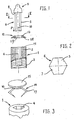
- Fig. 1 shows an implant 1, comprising a substantially cylindrical part 2, which on its outside is provided with screw thread 3 and inwardly is provided with a hole 4.
- the outer wall of the part 2 may taper somewhat.
- the hole 4 is in the shape of a hexagon although other shapes are possible.
- the cross-section can also be substantially circular with small extensions either impressions.
- the hexagon shape is prefered. Then the abutment can be positioned in the implant in six different positions while a good grip is obtained for the tool by which the implant is fixed into the jaw. As a tool it can be thought of a wrench for hexagon-socket head screws.
- the solid pin 5 of an abutment 6 kan be slid, as indicated by the arrow P in fig. 1.
- the pin 5 as well has a hexagon cross-section such that it can be fittingly received in the hole 4.
- the cross-section of the pin 5 and the hole 4 will be such that the pin 5 cannot rotate in the hole 4.
- the pin 5 of the abutment 6 in the hole 4 use is made of dentistry cement.
- the pin is provided with longitudinal grooves 7, see fig. 2, debouching at the stop surface 8 of the upper part 9 of the abutment 6.
- the upper part 9 needs not to be rotation symmetrically in respect of the centre line 10 of the pin 5, but e.g. can have an extension to one side.
- two abutments 6 might be fabricated the extensions of which are making angles of 30° with each other.
- the extension might be positoned in not only six but in twelve different positions. So the number of possible positions can be doubled.
- an adapter ring 12 is provided between this surface 11 and the stop surface 8 of the abutment 6.
- the outer diameter of the stop surface 8 of the abutment 6 will substantially equal the outer diameter of the upper surface 13 of the adapter ring 12 and the outer diameter of the surface 18 of the adapter ring 12, engaging the upper surface 11 of the implant 1, will substantially equal the outer diameter of the implant.
- the outer surface of the adapter ring 12 might be curved.
- the abutment 6 should have to be removed out off the implant 1, primary the adapter ring 12 will be removed. Then use can be made of a clamping member with two or more opposite lying clamping edges being movable in respect of each other. Said clamping edges e.g. can be pressed towards each other in the space formed by the removing of the adapter ring 12 between the implant 1 and the abutment 6. Then the clamping edges can be moved away from each other in the direction of the center line 10, so that the parts 1 and 6 will be drawn away from each other.
- a corkscrew One night think of the working of a corkscrew.
- Removing the adapter ring 12 can be done by drilling away a part of it, after which the remaining part of the relatively thin ring can be removed.
- the adapter ring 12 has a double function. Primary a smooth transition is obtained of the implant 1 to the upper part 9 of the abutment 6 and secondly a gripping point can be obtained after removing the adapter ring 12 so that the abutment 6 can be removed out off the implant 1 also when a definite cementation has taken place.
- Fig. 3 shows the possibility to obtain a temporary closing of the hole 4 in the implant 1. This might be desirable during the period that the implant has to grow into the jaw bone.
- a knob 14 from a somewhat resilient material, which can be pressed into the hole 4 in the implant 1 directly after the implant is mounted in the jaw bone and so is not yet suited for bringing the abutment 6 into it.
- the knob 14 comprises an upper plate 15 engaging the upper surface 11 of the implant 1, a hexagonal part 16 being clampingly engaged in the hole 4 in the implant 1 and some resilient legs 17 to obtain additional clamping force.
Landscapes
- Health & Medical Sciences (AREA)
- Oral & Maxillofacial Surgery (AREA)
- Orthopedic Medicine & Surgery (AREA)
- Dentistry (AREA)
- Epidemiology (AREA)
- Life Sciences & Earth Sciences (AREA)
- Animal Behavior & Ethology (AREA)
- General Health & Medical Sciences (AREA)
- Public Health (AREA)
- Veterinary Medicine (AREA)
- Dental Prosthetics (AREA)
Applications Claiming Priority (2)
| Application Number | Priority Date | Filing Date | Title |
|---|---|---|---|
| NL1022783A NL1022783C2 (nl) | 2003-02-26 | 2003-02-26 | Werkwijze voor het verbinden van een kaak-implantaat met een abutment en middelen voor toepassing van de werkwijze. |
| NL1022783 | 2003-02-26 |
Publications (1)
| Publication Number | Publication Date |
|---|---|
| EP1452149A1 true EP1452149A1 (de) | 2004-09-01 |
Family
ID=32768727
Family Applications (1)
| Application Number | Title | Priority Date | Filing Date |
|---|---|---|---|
| EP03078950A Withdrawn EP1452149A1 (de) | 2003-02-26 | 2003-12-16 | Zusammenbau eines Zahnimplantates und eines Abutments, sowie Verfahren zum Verbinden des Abutments mit dem Implantat |
Country Status (2)
| Country | Link |
|---|---|
| EP (1) | EP1452149A1 (de) |
| NL (1) | NL1022783C2 (de) |
Cited By (3)
| Publication number | Priority date | Publication date | Assignee | Title |
|---|---|---|---|---|
| WO2007006390A1 (de) * | 2005-07-14 | 2007-01-18 | Gebr. Brasseler Gmbh & Co. Kg | Dentalimplantat |
| US20100196851A1 (en) * | 2007-07-16 | 2010-08-05 | Dentalpoint Ag | Dental implant |
| US20130209960A1 (en) * | 2010-01-28 | 2013-08-15 | Olivier BENHAMOU | Assembly of a dental implant and a prosthetic element |
Citations (4)
| Publication number | Priority date | Publication date | Assignee | Title |
|---|---|---|---|---|
| US4468200A (en) * | 1982-11-12 | 1984-08-28 | Feldmuhle Aktiengesellschaft | Helical mandibular implant |
| US5695334A (en) * | 1995-12-08 | 1997-12-09 | Blacklock; Gordon D. | Bendable and castable post and core |
| US5839898A (en) * | 1997-06-04 | 1998-11-24 | Fernandes; Americo | Ball retainer |
| US6315563B1 (en) * | 1998-04-08 | 2001-11-13 | IMZ FERTIGUNGS-UND VERTRIEBSGESELLSCHAFT FüR DENTALE TECHNOLOGIE MBH | Single-tooth enossal implant |
-
2003
- 2003-02-26 NL NL1022783A patent/NL1022783C2/nl not_active IP Right Cessation
- 2003-12-16 EP EP03078950A patent/EP1452149A1/de not_active Withdrawn
Patent Citations (4)
| Publication number | Priority date | Publication date | Assignee | Title |
|---|---|---|---|---|
| US4468200A (en) * | 1982-11-12 | 1984-08-28 | Feldmuhle Aktiengesellschaft | Helical mandibular implant |
| US5695334A (en) * | 1995-12-08 | 1997-12-09 | Blacklock; Gordon D. | Bendable and castable post and core |
| US5839898A (en) * | 1997-06-04 | 1998-11-24 | Fernandes; Americo | Ball retainer |
| US6315563B1 (en) * | 1998-04-08 | 2001-11-13 | IMZ FERTIGUNGS-UND VERTRIEBSGESELLSCHAFT FüR DENTALE TECHNOLOGIE MBH | Single-tooth enossal implant |
Cited By (5)
| Publication number | Priority date | Publication date | Assignee | Title |
|---|---|---|---|---|
| WO2007006390A1 (de) * | 2005-07-14 | 2007-01-18 | Gebr. Brasseler Gmbh & Co. Kg | Dentalimplantat |
| US20100196851A1 (en) * | 2007-07-16 | 2010-08-05 | Dentalpoint Ag | Dental implant |
| US9072566B2 (en) * | 2007-07-16 | 2015-07-07 | Dentalpoint Ag | Dental implant |
| US20130209960A1 (en) * | 2010-01-28 | 2013-08-15 | Olivier BENHAMOU | Assembly of a dental implant and a prosthetic element |
| US9381073B2 (en) * | 2010-01-28 | 2016-07-05 | Sudimplant | Assembly of a dental implant and a prosthetic element |
Also Published As
| Publication number | Publication date |
|---|---|
| NL1022783C2 (nl) | 2004-08-30 |
Similar Documents
| Publication | Publication Date | Title |
|---|---|---|
| EP0195006B1 (de) | Implantat zur befestigung von zahnprothesen | |
| US11937992B1 (en) | Screw-attached pick-up dental coping system and methods | |
| US6287115B1 (en) | Dental implant and tool and method for effecting a dental restoration using the same | |
| US4832601A (en) | Adjustable support for a prosthetic tooth and method | |
| CA2395221C (en) | Impression jig assembly for use with dental implants | |
| US6012923A (en) | Two-piece dental abutment with removable cuff | |
| US7780448B2 (en) | Dental implant device and correction device therefor | |
| WO1988003007A1 (en) | Dental prostheses | |
| AU2004231328B2 (en) | Method for reversible fixing of a tool to an implantable element and device for carrying out such a fixing method | |
| KR20090117813A (ko) | 치과용 임플란트, 지대치 구조, 및 치과용 임플란트의 이식 방법 | |
| CN112105314A (zh) | 用于骨内牙种植体的基牙 | |
| JP2005503887A5 (de) | ||
| EP1452149A1 (de) | Zusammenbau eines Zahnimplantates und eines Abutments, sowie Verfahren zum Verbinden des Abutments mit dem Implantat | |
| AU718185B2 (en) | Releasable holding device preventing undesirable rotation during tightening of a screw connection in a bone anchored implant | |
| AU706046B2 (en) | Dental implant device | |
| US6814577B2 (en) | Dental prosthesis abutment and waxing sleeve assembly | |
| EP0893105B1 (de) | Zahnimplantat | |
| EP0525296B1 (de) | Zahnimplantataufbau mit einem Implantatstift und einem auswechselbaren, in der Höhe der Gingivadicke anpassbaren Halteteil | |
| IT201800010367A1 (it) | Impianto dentale | |
| JP4261981B2 (ja) | 歯科用インプラントシステム | |
| KR20040001000A (ko) | 치과용임플란트와 이를 사용하여 임플란팅하는 방법 | |
| WO2024170966A1 (en) | Modular dental implant | |
| WO1998040029A1 (en) | Dental implant and method and apparatus for installing the same | |
| KR20210001275A (ko) | 어버트먼트 고정장치 | |
| WO2006022565A1 (en) | Universal torque wrench for dental implant systems |
Legal Events
| Date | Code | Title | Description |
|---|---|---|---|
| PUAI | Public reference made under article 153(3) epc to a published international application that has entered the european phase |
Free format text: ORIGINAL CODE: 0009012 |
|
| AK | Designated contracting states |
Kind code of ref document: A1 Designated state(s): AT BE BG CH CY CZ DE DK EE ES FI FR GB GR HU IE IT LI LU MC NL PT RO SE SI SK TR |
|
| AX | Request for extension of the european patent |
Extension state: AL LT LV MK |
|
| 17P | Request for examination filed |
Effective date: 20041111 |
|
| AKX | Designation fees paid |
Designated state(s): AT BE BG CH CY CZ DE DK EE ES FI FR GB GR HU IE IT LI LU MC NL PT RO SE SI SK TR |
|
| STAA | Information on the status of an ep patent application or granted ep patent |
Free format text: STATUS: THE APPLICATION IS DEEMED TO BE WITHDRAWN |
|
| 18D | Application deemed to be withdrawn |
Effective date: 20080701 |