EP1452255A2 - Bohrfutter, insbesondere zum Schlagbohren - Google Patents
Bohrfutter, insbesondere zum Schlagbohren Download PDFInfo
- Publication number
- EP1452255A2 EP1452255A2 EP04010757A EP04010757A EP1452255A2 EP 1452255 A2 EP1452255 A2 EP 1452255A2 EP 04010757 A EP04010757 A EP 04010757A EP 04010757 A EP04010757 A EP 04010757A EP 1452255 A2 EP1452255 A2 EP 1452255A2
- Authority
- EP
- European Patent Office
- Prior art keywords
- locking
- ring
- chuck
- clamping
- clamping ring
- Prior art date
- Legal status (The legal status is an assumption and is not a legal conclusion. Google has not performed a legal analysis and makes no representation as to the accuracy of the status listed.)
- Granted
Links
Images


Classifications
-
- B—PERFORMING OPERATIONS; TRANSPORTING
- B23—MACHINE TOOLS; METAL-WORKING NOT OTHERWISE PROVIDED FOR
- B23B—TURNING; BORING
- B23B31/00—Chucks; Expansion mandrels; Adaptations thereof for remote control
- B23B31/02—Chucks
- B23B31/10—Chucks characterised by the retaining or gripping devices or their immediate operating means
- B23B31/12—Chucks with simultaneously-acting jaws, whether or not also individually adjustable
- B23B31/1207—Chucks with simultaneously-acting jaws, whether or not also individually adjustable moving obliquely to the axis of the chuck in a plane containing this axis
- B23B31/1238—Jaws movement actuated by a nut with conical screw-thread
-
- B—PERFORMING OPERATIONS; TRANSPORTING
- B23—MACHINE TOOLS; METAL-WORKING NOT OTHERWISE PROVIDED FOR
- B23B—TURNING; BORING
- B23B31/00—Chucks; Expansion mandrels; Adaptations thereof for remote control
- B23B31/02—Chucks
- B23B31/10—Chucks characterised by the retaining or gripping devices or their immediate operating means
- B23B31/12—Chucks with simultaneously-acting jaws, whether or not also individually adjustable
- B23B31/1207—Chucks with simultaneously-acting jaws, whether or not also individually adjustable moving obliquely to the axis of the chuck in a plane containing this axis
- B23B31/1215—Details of the jaws
-
- B—PERFORMING OPERATIONS; TRANSPORTING
- B23—MACHINE TOOLS; METAL-WORKING NOT OTHERWISE PROVIDED FOR
- B23B—TURNING; BORING
- B23B31/00—Chucks; Expansion mandrels; Adaptations thereof for remote control
- B23B31/02—Chucks
- B23B31/10—Chucks characterised by the retaining or gripping devices or their immediate operating means
- B23B31/12—Chucks with simultaneously-acting jaws, whether or not also individually adjustable
- B23B31/1207—Chucks with simultaneously-acting jaws, whether or not also individually adjustable moving obliquely to the axis of the chuck in a plane containing this axis
- B23B31/123—Chucks with simultaneously-acting jaws, whether or not also individually adjustable moving obliquely to the axis of the chuck in a plane containing this axis with locking arrangements
-
- B—PERFORMING OPERATIONS; TRANSPORTING
- B23—MACHINE TOOLS; METAL-WORKING NOT OTHERWISE PROVIDED FOR
- B23B—TURNING; BORING
- B23B2231/00—Details of chucks, toolholder shanks or tool shanks
- B23B2231/38—Keyless chucks for hand tools
-
- B—PERFORMING OPERATIONS; TRANSPORTING
- B23—MACHINE TOOLS; METAL-WORKING NOT OTHERWISE PROVIDED FOR
- B23B—TURNING; BORING
- B23B2231/00—Details of chucks, toolholder shanks or tool shanks
- B23B2231/44—Nose pieces
-
- Y—GENERAL TAGGING OF NEW TECHNOLOGICAL DEVELOPMENTS; GENERAL TAGGING OF CROSS-SECTIONAL TECHNOLOGIES SPANNING OVER SEVERAL SECTIONS OF THE IPC; TECHNICAL SUBJECTS COVERED BY FORMER USPC CROSS-REFERENCE ART COLLECTIONS [XRACs] AND DIGESTS
- Y10—TECHNICAL SUBJECTS COVERED BY FORMER USPC
- Y10S—TECHNICAL SUBJECTS COVERED BY FORMER USPC CROSS-REFERENCE ART COLLECTIONS [XRACs] AND DIGESTS
- Y10S279/00—Chucks or sockets
- Y10S279/902—Keyless type socket
-
- Y—GENERAL TAGGING OF NEW TECHNOLOGICAL DEVELOPMENTS; GENERAL TAGGING OF CROSS-SECTIONAL TECHNOLOGIES SPANNING OVER SEVERAL SECTIONS OF THE IPC; TECHNICAL SUBJECTS COVERED BY FORMER USPC CROSS-REFERENCE ART COLLECTIONS [XRACs] AND DIGESTS
- Y10—TECHNICAL SUBJECTS COVERED BY FORMER USPC
- Y10T—TECHNICAL SUBJECTS COVERED BY FORMER US CLASSIFICATION
- Y10T279/00—Chucks or sockets
- Y10T279/17—Socket type
- Y10T279/17615—Obliquely guided reciprocating jaws
- Y10T279/17623—Threaded sleeve and jaw
- Y10T279/17632—Conical sleeve
-
- Y—GENERAL TAGGING OF NEW TECHNOLOGICAL DEVELOPMENTS; GENERAL TAGGING OF CROSS-SECTIONAL TECHNOLOGIES SPANNING OVER SEVERAL SECTIONS OF THE IPC; TECHNICAL SUBJECTS COVERED BY FORMER USPC CROSS-REFERENCE ART COLLECTIONS [XRACs] AND DIGESTS
- Y10—TECHNICAL SUBJECTS COVERED BY FORMER USPC
- Y10T—TECHNICAL SUBJECTS COVERED BY FORMER US CLASSIFICATION
- Y10T279/00—Chucks or sockets
- Y10T279/32—Means to prevent jaw loosening
Definitions
- the invention relates to a drill chuck with the features according to the preamble of claim 1.
- Drill chucks of this type can be clamped by hand Drill chuck known from DE 43 13 742 C1.
- the self-tightening Linings with an analog structure are in DE 23 41 642 A1 described.
- chucks In the case of chucks that can only be tightened by hand, they are Clamping jaws are guided in the chuck body and stand over one Cheek teeth with a clamping thread on the clamping ring in the Intervention. With self-tightening chucks are against the jaws are guided on the clamping ring and axially on an in Direction around the chuck axis with the jaws rotatably held clamping head, which in one in Chuck body provided thread is rotatable.
- the stops limit the rotatability the collar opposite the chuck body and the Locking device is between the clamping ring and one Drag ring effective, with the wreath of Locking recesses on the clamping ring and the locking member on Drag ring located under the power of a Adjustment spring stands and its rotation relative to Chuck body on one for re-adjustment Clamping jaw permitted travel is limited.
- the Locking device is also between the collar and trained the tow ring. It is used when open Drill chuck the mutual turning of the collar and Secure the drag ring and with the drill chuck closed rule out that the collar in drilling operation automatically adjusted relative to the drag ring. Will the Collar relative to the tow ring in the closing of the Corresponding to the direction of rotation of the clamping ring twisted, the locking member moves from the to the Locked recessed state in the disengaged State, and vice versa.
- the invention has for its object a drill chuck of the type mentioned in the simplest possible way train that there is only to tension and loosen one part and therefore only one Hand needs to be operated, the defined one Adjustment of the locking element over the entire service life of the chuck should be ensured.
- the collar is used both for adjusting the locking member and Rotation of the clamping ring when adjusting the clamping jaws, the former taking place along the rotational path by which the Collar opposite the clamping ring between the stops is rotatable.
- the locking device has the purpose of safely make sure that with the drill chuck open the clamping ring from Collar is taken when twisting, without that Blocking element is moved into the engaged state, or when the chuck is under tension, the collar is opposite can not turn the clamping ring so that the locking member goes into the disengaged state.
- the actuation of the drill chuck according to the invention is solely by the Collar possible that only to be twisted and even only needs to be accessible by hand, to close, clamp and lock the drill chuck, or to unlock, unlock and open what the Handling compared to the well-known drill chucks significantly simplified, especially when clamping and loosening the drill chuck using the Drilling machine drive should take place via the drilling spindle and only one hand to hold the collar free is.
- the rotation of the adjusting ring in relation to the clamping ring is limited by the stops and the adjustment of the Locking member ensured in the locking recesses.
- the locking spring and the detent spring are together by one Spring clip formed, which extends in the circumferential direction along the The tension ring extends and is connected to it in a rotationally locking manner is.
- the spring clip both as Locking spring as well as a detent spring results manufacturing and manufacturing technology very simple and advantageous construction of the drill chuck.
- the spring clip points an outward bias as well as to the system the chuck body coming and exerting a braking effect Spring bars on.
- the spring bars are used to dampen the Vibrations occurring on the chuck body during drilling operation, Tension ring and collar provided.
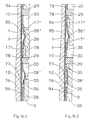
- the locking device has the coaxial ring of locking recesses, the the engaged locking member so inclined in each other Flank surfaces that this the clamping ring in the Open the drill chuck against the corresponding direction of rotation Lock twisting when twisting the clamping ring in the opposite, i.e. the closing of the drill chuck corresponding direction of rotation but the locking member against Force of the locking spring from the locking recesses push out and thereby from the locking recess Allow the locking recess to slide. Furthermore, the Arrangement made so that the locking member on the clamping ring and the locking receptacles are provided on the collar.
- the clamping ring has a coaxial Intermediate ring, which the clamping ring-side parts of the Stops for the collar and the spring bracket carries and has a collar part that the tension thread supporting part of the clamping ring rotatably encloses.
- stop piece as a radially inwardly directed cam is formed on the inside of the wall of the collar. It can the recess as a window in an axial direction front, approximately conical tapered collar of the intermediate ring be trained.
- the spring clip is formed in the circumferential direction extending spring arm, which in the engaged state of the Locking member of the control curve at a distance from Locking member is present, which is the springing of the spring arm the position of the locking member by its depth of engagement in the Blocking exceptions enabled. Then it is recommended that Arrangement to be made so that two in Circumferential distance at a distance Projections are provided, one of which locking member-side projection on the contact of the spring arm the cam and the other projection the locking member Latching device forms.
- a first possibility for arranging the spring clip is characterized in that the spring clip in one between the clamping ring and the collar in Circumferential slot arranged and on Clamping ring is positively secured against twisting that the ring wall of the clamping ring with a window for the Passage of the locking member into the locking recesses is provided, and that the slot at least in the area of the locking member the locking adjustments of the locking member enabling expansion. It consists in individual the possibility that the spring clip with Lining axis radial alignment of the spring band surface in Slot lies and the locking recesses radially on one on the chuck body side, perpendicular to the chuck axis Ring surface run.
- the intermediate ring forms the wall of the Intermediate ring preferably a radially directed Washer axially between which the locking recesses having ring surface and a radial ring shoulder of the collar is located between the washer and the ring shoulder of the spring bracket Slot is located and the control curve as well as the Locking on the ring shoulder, the window for the Passage of the locking member and the slot extension for the locking member are formed on the annular disc.
- the spring clip can be secured against rotation expediently the intermediate ring with its Stop pieces push the spring clip into openings, whose edges in the circumferential direction the stop pieces issue.
- Another advantageous way of arranging the Spring clip is for a clamping ring with an intermediate ring characterized in that with its spring band surface spring clips aligned parallel to the chuck axis in one in the circumferential direction between the chuck body and the Intermediate ring extending ring slot is the on the chuck body side from the rim of the axially extending Locking recesses is limited, and that the spring clip with outward bias is applied to the intermediate ring and with its two projections the intermediate ring in Extends out windows in which the spring clip is held against twisting.
- the ring slot is radially wider than that Spring clip is thick that the spring clip with an approximately located in the middle between the two projections Vertex area supported radially outwards on the intermediate ring is and between this vertex area and the two Projections each one of the spring bars to the tangential Forms on the wreath of the recesses.
- the one forming the latching member bears Projection on the apex area of the spring clip side facing away from the wreath of the locking recesses under pretension the tangent spring legs.
- the intermediate ring in another window has radially outward projection that in a the groove provided on the inside wall of the adjusting ring engages, which are at least above the maximum in the circumferential direction possible rotation of the collar compared to Tension ring extends and with at least one of them Side walls form an axial contact for the projection, whereby the collar against axial displacement on the clamping ring is secured.
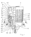
- the drill chucks shown in the drawing are used for Recording a drill, not shown, and each have a chuck body 1 for connection to one also not shown drilling spindle.
- the chuck body has a thread holder 2.
- the Drill chucks have the drill centering axially leading and / or clamping jaws 5, which in the to the chuck axis 3 coaxial tool holder 4 centric are adjustable to the chuck axis. About this adjustment serves a clamping ring 8, the axially on the chuck body 1 guided immovable and rotatable and axially to the rear via a ball bearing 22, optionally via a Pressure ring 21 is supported on the chuck body 1.
- This rotation of the adjusting ring 9 relative to the clamping ring 8 is positive in both directions of rotation (arrows 14, 15) limited, for which stops 16 ', 16 "are provided Turning the collar 9 in the closing of the Drill chuck corresponding direction of rotation (arrow 15) the locking member 12 is adjusted from the disengaged State in the indented state and vice versa, so by turning the collar 9 in the opening of the Corresponding to the direction of rotation (arrow 14) from the indented state in the disengaged state.
- a 17 designated locking device provided in Has two locking positions, circumferential direction in the one locking position, the locking member 12 in the at Locking recesses 10 indented state and in the other rest position in the disengaged state, such as a comparison of the figure pairs 4.1, 4.2 and 11.1, 11.2 or 13.1, 13.2 or 21.1, 21.2.
- a locking spring acted on locking member 38 "on the Side of the clamping ring 8 in accordance with the collar 9 arranged locking receptacles 17 "formed.
- the locking spring and the detent springs are common to a spring clip 38 formed in the circumferential direction along the Clamping ring 8 extends and rotatably with the clamping ring 8th connected is.
- FIGS. 1 to 18 show from Hand-chuck drill chuck, in which the jaws 5 guided in the chuck body 1 and a jaw teeth 6 engages with a clamping thread 7 'on the clamping ring 8 stand.
- the clamping ring 8 has a chuck that can be tightened by hand a coaxial form a guide for the collar 9 Intermediate ring 18, the parts of the clamping ring side Stops 16 ', 16 "for the collar and also the Spring bracket 38 carries, and includes a collar part 18 ', the part of the Clamping rings 8 rotatably encloses.
- the Clamping thread 7 'bearing part 18 "of the clamping ring 8 two circumferentially divided, namely initially on each Division weakened through a hole 19 and then broken ring halves in an annular groove 20 of the Lining body 1 assembled against each other and by the collar part 18 'held together on the chuck body 1 are.
- the clamping ring 8 can also be formed in one piece, but what in the drawing is not shown further.
- the clamping ring 8 or intermediate ring 18 has the radial Guide of the collar 9 a circular cylindrical Outer surface 60 of the clamping sleeve 9 with a corresponds to the circular cylindrical inner surface 61.
- Adjustment ring 9 against axial displacement to the front either also on the intermediate ring 18, as below will be described in more detail, or in the axial area behind the clamping ring 8 on the chuck body 1, for example on one connected to the chuck body 1 End ring 40 take place, which also for radial guidance of the collar 9 in the area of its rear ring end can contribute.
- stop pieces generally designated 29 on one ring 8 or 9 and a recess 30 receiving the stop piece 29 on the other Ring provided, the stop piece 29 at the ends of the path of rotation each with one of the two recesses 30 delimiting the circumferential end faces 16 ', 16 "to the stop.
- three such stop pieces 29 or Cutouts 30 available.
- the stop pieces 29 can be designed as wall pieces of the intermediate ring 18 which project axially forward from the front edge of the intermediate ring 18 into the recesses 30 formed on the inside of the adjusting ring 9 on the wall ,
- the stop pieces 29 can extend through the recesses 30 axially up to the front edge 64 of the adjusting ring 9 and there can be formed at their front end as an axial stop for the adjusting ring, which secures the adjusting ring 9 axially to the front against displacement.
- the stop pieces 29 are connected to one another at their lower end in the circumferential direction by a ring 65, which on its edge facing away from the stop pieces 29 carries tongues 66 which are bent onto the front end face of the adjusting ring 9.
- the stop pieces 29 penetrate slots provided in the wall of the adjusting ring 9, which run in the circumferential direction along an arc and form the cutouts 30.
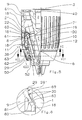
- 5 to 8 show a further embodiment of a drill chuck with axial guidance of the adjusting ring 9 only on the intermediate ring 18.
- the stop pieces 29 as radially inwardly directed cams on the inside of the adjusting ring 9 and the recesses 30 as windows in an axially directed manner Conical tapered collar 69 of the intermediate ring 18 formed at the front.
- the radially inner surface 29 'of the cams 29 is at a distance from the chuck axis 3, which is at least equal to the largest outer diameter 80' of the window edge 80 on the intermediate ring 18, so that the cams 29 forming the stop pieces 29 push the adjusting ring 9 onto the intermediate ring 18 do not hinder.
- the cams 29 each carry a radially resilient latching lug 81, which engages behind the axially front edge 80 of the window 30 when the adjusting ring 9 is completely pushed onto the intermediate ring 18 and thereby secures the clamping sleeve 9 axially to the front, as is shown in detail in FIG. 8 can be seen.
- the spring clip 38 forms in all exemplary embodiments a spring arm 36 extending in the circumferential direction, which has the locking member 12 at the free arm end.
- the Spring arm 36 on the control cam 35 in the engaged state of the locking member 12 is the Spring arm 36 on the control cam 35 at a distance from Locking member 12 on which the spring arm 35 springs through the position of the locking member 12 by at least its Depth of engagement in the locking recesses 10 allows so that when tightening the chuck the locking member 12 over the Wreath of locking recesses 10 can slide away.
- the Spring clips 38 are two in the circumferential direction in mutually spaced projections 38 ', 38 " intended. Of these, the pusher side forms Projection 38 'the system of the spring arm 36 on the Control curve 35, the other projection 38 "the locking member Latching device 17.
- the spring clip 38 is through a Spring band and the locking member 12 directly through the formed rear end of the spring band, seen in the direction of rotation corresponding to the closing of the chuck the clamping ring 8 (arrow 15).
- the projections 38 ', 38 are each in the form of bulges on the spring band being bent.
- the spring clip 38 in a between the clamping ring 8 and the adjusting ring 9 in the circumferential direction slit 94 arranged and positively against the clamping ring 8 Twisted secured in a manner to be described in more detail.
- the ring wall of the clamping ring 8 is with a window 77 for the passage of the locking member 12 in the Blocking recesses 10 provided.
- the Slot 94 in the area of the locking member 38 "a Enabling locking adjustments of the locking member Extension 95.
- the spring clip 38 lies with the chuck axis 3 radial alignment of the spring band surface in the slot 94 and the locking recesses 10 run radially accordingly a chuck body side, perpendicular to the chuck axis 3 standing ring surface 74.
- the wall of the intermediate ring 18th forms a radially directed washer 76, the axial between the one having the locking recesses 10 Annular surface 74 and a radial annular shoulder 75 of Collet 9 is. Between the washer 76 and the Ring shoulder 75 is the spring clip 38 receiving slot 94.
- the cam 35 and the Snap-in receptacles 17 are formed on the ring shoulder 75, the window for the passage of the locking member 12 and the Slot extension 95 for the locking member 38 "on the Ring disc 76.
- the intermediate ring 18 passes through with its Stop pieces 29 the spring clip 38 in openings whose Edges 78 in the circumferential direction of the stop pieces 29 rest so that the spring clip 38 does not face each other turn the intermediate ring 18 and thus the clamping ring 8 can.
- the chuck body side of Wreath of axially extending locking recesses 10 limited is.
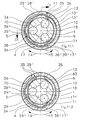
- the spring clip 38 lies with the outward Bias the intermediate ring 18 and engages with its two projections 38 ', 38 "the intermediate ring 18 in Windows 39 ', 39 "radially outward. These Window 39 ', 39 "through projections 38', 38” secure the spring clip 38 by a stop on the Window boundaries bordering the circumference against twisting relative to the intermediate ring 18.
- the radial Width of the ring slot 83 is larger than that corresponding thickness of the spring clip 38, which with an approximately centered between the two projections 38 ', 38 " located apex region 31 radially outwards on Intermediate ring 18 is supported and between this Vertex area 31 and the two projections 38 ', 38 "each a spring bar 34 for tangential contact with the rim of the Locking recesses 10 forms.
- the two projections 38 ', 38 are in relation to one another the chuck axis 3 approximately diametrically opposite. in the Embodiment according to FIGS. 9 to 11 has the Spring clip 38 in the apex area between his two Projections 38 ', 38 "a third, the intermediate ring 18 in another window 39 “'reaching outwards Projection 38 '' '.
- This groove 70 forms with its two side walls an axial system for the Projection 38 "', whereby the collar 9 against Axial displacements on the clamping ring 8 is secured so that in this case the ring shoulder 63 is also dispensed with could be.
- a comparable axial guide function is recommended for the two projections 38 ', 38 ", however not, because here the system of the spring clip 38 to the Side walls of corresponding grooves for the locking process or locking process required mobility of the two Projections 38 ', 38 "could impair.
- the Spring clip 72 also engages radially outward in one provided on the inside wall of the collar 9 Groove 73, which is like the groove 70 in the circumferential direction at least over the maximum possible twist path of the Collet 9 extends relative to the intermediate ring 18 and which also has an axial contact with its side walls for the spring clip 72, whereby the spring clip 72nd in the same way as the central projection 38 "'a Securing the collar 9 against axial displacement on Intermediate ring 18 results.
- a retaining ring 54 can also be in one piece be formed with the chuck body 1.
Landscapes
- Engineering & Computer Science (AREA)
- Mechanical Engineering (AREA)
- Gripping On Spindles (AREA)
- Percussive Tools And Related Accessories (AREA)
- Clamps And Clips (AREA)
- Drilling And Boring (AREA)
- Spinning Or Twisting Of Yarns (AREA)
- Apparatus For Making Beverages (AREA)
Abstract
Description
- Fig. 1
- ein Bohrfutter nach der Erfindung, links in einem Axialschnitt, rechts in einer Seitenansicht, jeweils in der Stellung der Spannbacken bei geringstem Spanndurchmesser und im ungesperrten Futterzustand,
- Fig. 2
- den Schnitt II - II in Fig. 1,
- Fig. 3
- den Schnitt III - III in Fig. 1,
- Fig. 4
- den Schnitt IV - IV in Fig. 1, und zwar in der Teilfig. 4.1 im ungesperrten, in der Teilfig. 4.2 im gesperrten Futterzustand,
- Fig. 5
- eine andere Ausführungsform des Bohrfutters nach der Erfindung in einer der Fig. 1 entsprechenden Darstellung,
- Fig. 6
- den Schnitt VI - VI in Fig. 5,
- Fig. 7
- den Schnitt VII - VII in Fig. 5,
- Fig. 8
- das in Fig. 5 mit VIII bezeichnete Detail in vergrößerter Darstellung,
- Fig. 9
- eine weitere Ausführungsform des erfindungsgemäßen Bohrfutters,
- Fig. 10
- den Schnitt X - X in Fig. 9,
- Fig. 11
- den Schnitt XI - XI in Fig. 9, und zwar in der Teilfig. 11.1 im ungesperrten, in der Teilfig. 11.2 im gesperrten Futterzustand,
- Fig. 12
- eine weitere Ausführungsform des erfindungsgemäßen Bohrfutters in einer der Fig. 1 entsprechenden Darstellung,
- Fig. 13
- den Schnitt XIII - XIII in Fig. 12, und zwar in den Teilfig. 13.1 im ungesperrten, in der Teilfig. 13.2 im gesperrten Futterzustand,
- Fig. 14
- eine wiederum andere Ausführungsform des Bohrfutters nach der Erfindung in einer der Fig. 1 entsprechenden Darstellung,
- Fig. 15
- den Schnitt XV - XV in Fig. 14,
- Fig. 16
- den Schnitt XVI - XVI in Fig. 14 in einer Abwicklung in Umfangsrichtung, und zwar in der Teilfig. 16.1 im ungesperrten, in der Teilfig. 16.2 im gesperrten Futterzustand,
- Fig. 17
- nur den Zwischenring des Bohrfutters nach Fig. 14 im Axialschnitt, und
- Fig. 18
- eine Draufsicht auf den Zwischenring der Fig. 17.
Aussparungen 30 vorhanden. Im einzelnen können, wie in den Fig. 1 bis 4 oder 9 bis 18, die Anschlagstücke 29 als Wandstücke des Zwischenrings 18 ausgebildet sein, die vom vorderen Rand des Zwischenrings 18 axial nach vorn in die auf der Wandinnenseite des Stellrings 9 ausgebildeten Aussparungen 30 vorstehen. Die Anschlagstücke 29 können die Aussparungen 30 axial bis zum vorderen Rand 64 des Stellrings 9 durchgreifen und dort an ihrem vorderen Ende als axialer Anschlag für den Stellring ausgebildet sein, der den Stellring 9 gegen Verschieben axial nach vorn sichert. Dazu sind in den Fig. 1 bis 4 die Anschlagstücke 29 an ihrem unteren Ende in Umfangsrichtung durch einen Ring 65 miteinander verbunden, der an seinem den Anschlagstücken 29 abgewandten Rand Zungen 66 trägt, die auf die vordere Stirnfläche des Stellrings 9 umgebogen sind. Im Ausführungsbeispiel nach den Fig. 9 bis 11 durchsetzen die Anschlagstücke 29 in der Wand des Stellrings 9 vorgesehene Schlitze, die in Umfangsrichtung längs eines Kreisbogens verlaufen und die Aussparungen 30 bilden. Die Fig. 5 bis 8 zeigen ein weiteres Ausführungsbeispiel eines Bohrfutters mit axialer Führung des Stellrings 9 allein am Zwischenring 18. Dazu sind die Anschlagstücke 29 als radial einwärts gerichtete Nocken an der Wandinnenseite des Stellrings 9 und die Aussparungen 30 als Fenster in einem sich axial nach vorn konisch verjüngenden Kragen 69 des Zwischenrings 18 ausgebildet. Die radial innen liegende Fläche 29' der Nocken 29 besitzt einen Abstand von der Futterachse 3, der mindestens gleich dem größten Außendurchmesser 80' des Fensterrands 80 am Zwischenring 18 ist, so daß die die Anschlagstücke 29 bildenden Nocken das Aufschieben des Stellrings 9 auf den Zwischenring 18 nicht behindern. Die Nocken 29 tragen jeweils eine radial federnde Rastnase 81, die bei auf den Zwischenring 18 vollständig aufgeschobenem Stellring 9 hinter dem axial vorderen Rand 80 des Fensters 30 einrastet und dadurch die Spannhülse 9 gegen Verschieben axial nach vorn sichert, wie dies im einzelnen aus Fig. 8 ersichtlich ist.
Claims (4)
- Bohrfutter, insbesondere zum Schlagbohren, mit einem an eine Bohrspindel anschließbaren Futterkörper (1), mit zwischen sich eine Aufnahme (4) für das Bohrwerkzeug bildenden, im Futterkörper (1) geführten Spannbacken (5), die zum Öffnen und Schließen des Bohrfutters durch einen am Futterkörper (1) drehbar geführten Spannring (8) mit einem an den Spannbacken (5) im Eingriff stehenden Spanngewinde (7') verstellbar sind, ferner mit einer mittels mindestens eines mit einer Sperrfeder zusammenwirkenden Sperrgliedes (12) unerwünschte Verstellungen der Spannbacken (5) verhindernden Sperreinrichtung (11) zur Fixierung der Drehstellung des Spannrings (8) gegenüber dem Futterkörper (1), weiter mit einem zwischen Anschlägen (16', 16") begrenzt verdrehbaren koaxialen Stellring (9), durch dessen Verdrehen das Sperrglied (12) verstellbar ist, und mit einer selbstätige und unerwünschte Drehungen des Stellrings (9) gegenüber dem Spannring (8) verhindernden Rasteinrichtung (17) mit einem Rastglied (38''), dadurch gekennzeichnet, daß zwischen dem Stellring (9) und dem Spannring (8) die Rasteinrichtung (17) vorgesehen ist, die in Umfangsrichtung zwei Raststellungen aufweist, wobei sich in der einen Raststellung das Sperrglied (12) in dem an den Sperrausnehmungen (10) eingerückten Zustand und in der anderen Raststellung im ausgerückten Zustand befindet, das der Sperreingriff des Sperrgliedes (12) in die Sperrausnehmungen (10) und der Rasteingriff des Rastgliedes (38'') in derselben, zur Futterachse senkrechten Ebene liegen, und daß das Anschlagstück (29) als radial einwärts gerichteter Nocken an der Wandinnenseite des Stellrings (9) ausgebildet ist.
- Bohrfutter nach Anspruch 1, dadurch gekennzeichnet, daß das eingerückte Sperrglied (12) den Sperrausnehmungen (10) in einander derart geneigten Flankenflächen (13', 13") anliegt, daß diese den Spannring (8) in der dem Öffnen des Bohrfutters entsprechenden Drehrichtung gegen Verdrehen sperren, beim Verdrehen des Spannrings (8) in der entgegen gesetzten, also dem Schließen des Bohrfutters entsprechenden Drehrichtung aber das Sperrglied (12) gegen die Kraft der Sperrfeder aus den Sperrausnehmungen (10) herausdrücken und dadurch von Sperrausnehmung (10) zu Sperrausnehmung (10) verrutschen lassen.
- Bohrfutter nach einem der Ansprüche 1 oder 2, dadurch gekennzeichnet, daß der Spannring (8) einen koaxialen Zwischenring (18) aufweist.
- Bohrfutter nach einem der Ansprüche 1 bis 3, dadurch gekennzeichnet, daß das Anschlagstück (29) an den Enden des Drehweges jeweils mit einer der beiden Stirnflächen zum Anschlag kommt, die eine das Anschlagstück (29) aufnehmende Aussparung (30) in Umfangsrichtung begrenzen.
Priority Applications (2)
| Application Number | Priority Date | Filing Date | Title |
|---|---|---|---|
| EP06014430A EP1724041A1 (de) | 1994-10-31 | 1995-04-10 | Bohrfutter, insbesondere zum Schlagbohren |
| EP07005517A EP1792678B1 (de) | 1994-10-31 | 1995-04-10 | Bohrfutter, insbesondere zum Schlagbohren |
Applications Claiming Priority (5)
| Application Number | Priority Date | Filing Date | Title |
|---|---|---|---|
| DE4438991 | 1994-10-31 | ||
| DE4438991A DE4438991C5 (de) | 1994-10-31 | 1994-10-31 | Bohrfutter |
| EP02001527A EP1224993B1 (de) | 1994-10-31 | 1995-04-10 | Bohrfutter |
| EP00113207A EP1043100B1 (de) | 1994-10-31 | 1995-04-10 | Bohrfutter |
| EP95105379A EP0710518B1 (de) | 1994-10-31 | 1995-04-10 | Bohrfutter |
Related Parent Applications (1)
| Application Number | Title | Priority Date | Filing Date |
|---|---|---|---|
| EP02001527A Division EP1224993B1 (de) | 1994-10-31 | 1995-04-10 | Bohrfutter |
Related Child Applications (1)
| Application Number | Title | Priority Date | Filing Date |
|---|---|---|---|
| EP06014430A Division EP1724041A1 (de) | 1994-10-31 | 1995-04-10 | Bohrfutter, insbesondere zum Schlagbohren |
Publications (3)
| Publication Number | Publication Date |
|---|---|
| EP1452255A2 true EP1452255A2 (de) | 2004-09-01 |
| EP1452255A3 EP1452255A3 (de) | 2004-12-15 |
| EP1452255B1 EP1452255B1 (de) | 2006-08-30 |
Family
ID=6532213
Family Applications (9)
| Application Number | Title | Priority Date | Filing Date |
|---|---|---|---|
| EP95105380A Expired - Lifetime EP0710519B1 (de) | 1994-10-31 | 1995-04-10 | Bohrfutter |
| EP00113207A Expired - Lifetime EP1043100B1 (de) | 1994-10-31 | 1995-04-10 | Bohrfutter |
| EP06014430A Withdrawn EP1724041A1 (de) | 1994-10-31 | 1995-04-10 | Bohrfutter, insbesondere zum Schlagbohren |
| EP95105379A Expired - Lifetime EP0710518B1 (de) | 1994-10-31 | 1995-04-10 | Bohrfutter |
| EP07005517A Expired - Lifetime EP1792678B1 (de) | 1994-10-31 | 1995-04-10 | Bohrfutter, insbesondere zum Schlagbohren |
| EP00116860A Expired - Lifetime EP1055472B1 (de) | 1994-10-31 | 1995-04-10 | Bohrfutter |
| EP04010757A Expired - Lifetime EP1452255B1 (de) | 1994-10-31 | 1995-04-10 | Bohrfutter, insbesondere zum Schlagbohren |
| EP02001527A Expired - Lifetime EP1224993B1 (de) | 1994-10-31 | 1995-04-10 | Bohrfutter |
| EP95105407A Expired - Lifetime EP0710520B1 (de) | 1994-10-31 | 1995-04-10 | Bohrfutter |
Family Applications Before (6)
| Application Number | Title | Priority Date | Filing Date |
|---|---|---|---|
| EP95105380A Expired - Lifetime EP0710519B1 (de) | 1994-10-31 | 1995-04-10 | Bohrfutter |
| EP00113207A Expired - Lifetime EP1043100B1 (de) | 1994-10-31 | 1995-04-10 | Bohrfutter |
| EP06014430A Withdrawn EP1724041A1 (de) | 1994-10-31 | 1995-04-10 | Bohrfutter, insbesondere zum Schlagbohren |
| EP95105379A Expired - Lifetime EP0710518B1 (de) | 1994-10-31 | 1995-04-10 | Bohrfutter |
| EP07005517A Expired - Lifetime EP1792678B1 (de) | 1994-10-31 | 1995-04-10 | Bohrfutter, insbesondere zum Schlagbohren |
| EP00116860A Expired - Lifetime EP1055472B1 (de) | 1994-10-31 | 1995-04-10 | Bohrfutter |
Family Applications After (2)
| Application Number | Title | Priority Date | Filing Date |
|---|---|---|---|
| EP02001527A Expired - Lifetime EP1224993B1 (de) | 1994-10-31 | 1995-04-10 | Bohrfutter |
| EP95105407A Expired - Lifetime EP0710520B1 (de) | 1994-10-31 | 1995-04-10 | Bohrfutter |
Country Status (5)
| Country | Link |
|---|---|
| US (1) | US5765839A (de) |
| EP (9) | EP0710519B1 (de) |
| JP (1) | JP3774793B2 (de) |
| DE (13) | DE4438991C5 (de) |
| ES (7) | ES2176146T3 (de) |
Cited By (2)
| Publication number | Priority date | Publication date | Assignee | Title |
|---|---|---|---|---|
| US7837200B2 (en) | 2005-07-01 | 2010-11-23 | Jacobs Chuck Manufacturing Company | Chuck |
| CN101077536B (zh) * | 2006-05-23 | 2010-12-01 | 山东威达机械股份有限公司 | 斜楔面锁紧钻夹头 |
Families Citing this family (98)
| Publication number | Priority date | Publication date | Assignee | Title |
|---|---|---|---|---|
| CN1076235C (zh) * | 1995-08-11 | 2001-12-19 | 动力工具霍德尔斯公司 | 卡头 |
| DE59606508D1 (de) * | 1996-01-17 | 2001-04-05 | Roehm Gmbh | Bohrfutter |
| US5957469A (en) * | 1996-09-25 | 1999-09-28 | Power Tool Holders, Inc. | Spring chuck |
| US5741016A (en) * | 1996-10-02 | 1998-04-21 | Power Tool Holders Incorporated | Chuck |
| US5816583A (en) * | 1996-12-04 | 1998-10-06 | Power Tool Holders, Inc. | Integral locking sleeve chuck |
| US5913524A (en) * | 1997-10-08 | 1999-06-22 | Power Tool Holders, Inc. | Chuck with gripping mechanism stop |
| USD404630S (en) * | 1998-05-20 | 1999-01-26 | Black & Decker Inc. | Chuck |
| DE19832891C2 (de) * | 1998-07-22 | 2003-04-17 | Roehm Gmbh | Bohrfutter |
| DE19907331A1 (de) | 1999-02-20 | 2000-08-24 | Roehm Gmbh | Bohrfutter |
| USD423527S (en) * | 1999-07-13 | 2000-04-25 | Yukiwa Seiko Kabushiki Kaisha | Drill chuck |
| US6260856B1 (en) | 1999-11-17 | 2001-07-17 | Power Tool Holders Incorporated | Locking chuck |
| USD433909S (en) * | 1999-12-23 | 2000-11-21 | Ryobi North America, Inc. | Keyless drill chuck |
| USD434629S (en) * | 1999-12-23 | 2000-12-05 | Ryobi North America, Inc. | Keyless drill chuck |
| DE10008262B4 (de) | 2000-02-23 | 2007-03-15 | Röhm Gmbh | Verfahren zur Herstellung von Hartmetalleinsätze als Spannschneiden aufweisende Spannbacken für Bohrfutter, sowie entsprechend gefertigte Spannbacken |
| US6390481B1 (en) | 2000-03-10 | 2002-05-21 | Power Tool Holders Incorporated | Locking chuck |
| US6540237B1 (en) | 2000-06-23 | 2003-04-01 | Power Tool Holders Incorporated | Chuck |
| EP1170078B1 (de) * | 2000-07-03 | 2003-09-10 | Röhm GmbH | Bohrfutter mit einer eine Steuerkurve aufweisenden Spannhülse |
| EP1170079B2 (de) * | 2000-07-03 | 2010-10-06 | Röhm GmbH | Bohrfutter |
| US6517088B1 (en) * | 2000-08-08 | 2003-02-11 | Rohm Gmbh | Lockable drill chuck |
| DE10137281A1 (de) | 2000-08-10 | 2002-02-21 | Roehm Gmbh | Bohrfutter |
| JP4681716B2 (ja) * | 2000-08-14 | 2011-05-11 | ロェーム ゲーエムベーハー | 切り替え・調節用曲がり部を有する締付ケーシング筒を備えたドリルチャック |
| DE10101212A1 (de) | 2001-01-11 | 2002-07-18 | Roehm Gmbh | Bohrfutter |
| CN1217762C (zh) | 2001-06-10 | 2005-09-07 | 山东威达机械股份有限公司 | 自锁钻夹头 |
| US6959931B2 (en) | 2001-08-30 | 2005-11-01 | Yukiwa Seiko Inc. | Keyless chuck and associated method |
| JP2003071618A (ja) | 2001-08-30 | 2003-03-12 | Yukiwa Seiko Inc | チャック装置 |
| US6824141B1 (en) | 2001-08-30 | 2004-11-30 | Yukiwa Seiko Kabushiki Kaisha | Chuck device |
| US6860488B2 (en) * | 2001-10-10 | 2005-03-01 | Rohm Gmbh | Drill chuck with front-end shield |
| USD461697S1 (en) | 2001-11-05 | 2002-08-20 | Techtronic Co., Ltd | Keyless drill chuck |
| USD472443S1 (en) | 2001-11-05 | 2003-04-01 | Techtronic Industries Co., Ltd | Keyless drill chuck |
| JP4015857B2 (ja) | 2002-01-18 | 2007-11-28 | ユキワ精工株式会社 | チャック装置 |
| JP4053301B2 (ja) | 2002-01-31 | 2008-02-27 | ユキワ精工株式会社 | チャック装置 |
| DE10207152B4 (de) * | 2002-02-20 | 2015-04-16 | Röhm Gmbh | Bohrvorrichtung |
| DE10226165A1 (de) * | 2002-06-12 | 2003-12-24 | Roehm Gmbh | Bohrfutter |
| DE10226429A1 (de) * | 2002-06-13 | 2003-12-24 | Roehm Gmbh | Bohrfutter |
| DE10237750A1 (de) * | 2002-08-17 | 2004-02-26 | Röhm Gmbh | Bohrfutter |
| FR2847180B1 (fr) * | 2002-11-18 | 2005-02-11 | Amyot Ets Sa | Mandrin porte-outil a systeme de verrouillage |
| JP4294945B2 (ja) * | 2002-12-06 | 2009-07-15 | ユキワ精工株式会社 | チャック装置 |
| CN2633481Y (zh) * | 2003-07-17 | 2004-08-18 | 山东威达机械股份有限公司 | 锁紧式钻夹头 |
| DE10335500A1 (de) * | 2003-07-31 | 2005-03-03 | Röhm Gmbh | Schnellspannbohrfutter |
| US20050087937A1 (en) * | 2003-10-22 | 2005-04-28 | Wenhua Zhou | Lock type manually tightened chuck |
| DE20317695U1 (de) * | 2003-11-14 | 2004-02-19 | Röhm Gmbh | Bohrvorrichtung |
| US7451990B2 (en) | 2004-04-29 | 2008-11-18 | Jacobs Chuck Manufacturing Company | Chuck with torque indicator |
| CN2715890Y (zh) * | 2004-08-03 | 2005-08-10 | 山东威达机械股份有限公司 | 带响自锁式钻夹头 |
| DE102004044824A1 (de) * | 2004-09-16 | 2006-03-23 | Röhm Gmbh | Bohrfutter |
| US7331584B2 (en) | 2004-09-17 | 2008-02-19 | Black & Decker Inc. | Chuck with nutating gear reduction |
| EP1861220A1 (de) * | 2005-03-19 | 2007-12-05 | Röhm GmbH | Bohrfutter |
| DE102005018392B4 (de) * | 2005-04-20 | 2019-10-31 | Röhm Gmbh | Bohrfutter |
| US7708288B2 (en) | 2005-05-18 | 2010-05-04 | Jacobs Chuck Manufacturing Company | Locking chuck |
| FR2886183B1 (fr) * | 2005-05-27 | 2007-07-13 | Amyot Sa Sa Ets | Mandrin porte-outil pour l'equipement d'une machine tournante, notamment du type "cle a choc" |
| US7472913B2 (en) * | 2005-06-09 | 2009-01-06 | Jacobs Chuck Manufacturing Company | Drill chuck |
| US7527273B2 (en) | 2005-09-02 | 2009-05-05 | Jacobs Chuck Manufacturing Company | Locking chuck |
| CN100578036C (zh) * | 2005-09-28 | 2010-01-06 | 山东威达机械股份有限公司 | 单向离合装置及采用该装置的柄类工具夹持结构 |
| DE102005048167B4 (de) * | 2005-10-06 | 2007-06-06 | Röhm Gmbh | Bohrfutter |
| US7637510B2 (en) * | 2005-10-12 | 2009-12-29 | Shandong Weida Machinery Company Limited | Chuck with gripping mechanism stop |
| USD537315S1 (en) * | 2005-10-20 | 2007-02-27 | Jacobs Chuck Manufacturing Company | Drill chuck sleeve |
| DE102005058657A1 (de) * | 2005-12-07 | 2007-06-14 | Röhm Gmbh | Bohrfutter |
| FR2897789B1 (fr) * | 2006-02-27 | 2008-05-09 | Amyot Sa Sa Ets | Mandrin porte-outil pour l'equipement d'une machine tourante muni de moyens de verrouillage radial et axial sequences |
| DE102006011344A1 (de) * | 2006-03-11 | 2007-09-13 | Röhm Gmbh | Bohrfutter |
| DE102007008314A1 (de) * | 2006-03-25 | 2007-09-27 | Röhm Gmbh | Nachspannendes Bohrfutter |
| DE102006024819B4 (de) * | 2006-05-29 | 2024-05-23 | Röhm Gmbh | Bohrfutter |
| US7845651B2 (en) | 2006-08-15 | 2010-12-07 | Jacobs Chuck Manufacturing Company | Locking chuck |
| DE102006043040A1 (de) * | 2006-09-14 | 2008-03-27 | Röhm Gmbh | Bohrfutter |
| DE102006050916A1 (de) * | 2006-10-28 | 2008-04-30 | Röhm Gmbh | Nachspannendes Bohrfutter |
| ES2327358T3 (es) * | 2006-12-23 | 2009-10-28 | Rohm Gmbh | Portabrocas. |
| US8057134B2 (en) | 2007-06-26 | 2011-11-15 | Techtronic Power Tools Technology Limited | Chuck assembly |
| US8075229B2 (en) * | 2007-06-26 | 2011-12-13 | Techtronic Power Tools Technology Limited | Multi-speed drill and chuck assembly |
| US7900937B2 (en) | 2007-08-17 | 2011-03-08 | Jacobs Chuck Manufacturing Company | Locking chuck |
| CN101497190B (zh) * | 2008-01-31 | 2012-03-28 | 苏州宝时得电动工具有限公司 | 电动工具 |
| US8403339B2 (en) | 2008-06-18 | 2013-03-26 | Jacobs Chuck Manufacturing Company | Self tightening chuck with an axial lock |
| US8376371B2 (en) | 2008-09-17 | 2013-02-19 | Jacobs Chuck Manufacturing Company | Locking chuck jaws |
| DE202009005187U1 (de) * | 2008-11-24 | 2009-10-29 | Zhejiang Sanou Machinery Co. Ltd., Taizhou | Schlüsselloses Bohrfutter mit Selbstverriegelung |
| US8777232B2 (en) | 2009-07-29 | 2014-07-15 | Jacobs Chuck Manufacturing Company | Self-tightening chuck with a radial lock |
| US9352397B2 (en) | 2012-04-10 | 2016-05-31 | Apex Brands, Inc. | Locking chuck |
| DE202012102742U1 (de) * | 2012-07-23 | 2013-04-25 | Röhm Gmbh | Bohrfutter |
| CN202779945U (zh) | 2012-08-01 | 2013-03-13 | 山东威达机械股份有限公司 | 钻夹头 |
| DE102012110809A1 (de) | 2012-11-12 | 2014-05-15 | Röhm Gmbh | Bohrfutter |
| US10556276B2 (en) * | 2013-03-14 | 2020-02-11 | Apex Brands, Inc. | Locking chuck |
| DE202013101255U1 (de) | 2013-03-25 | 2013-04-10 | Röhm Gmbh | Bohrfutter |
| DE102014002969A1 (de) * | 2014-03-06 | 2015-09-10 | Röhm Gmbh | Bohrfutter |
| DE102014106082B4 (de) | 2014-04-30 | 2025-07-03 | Röhm Gmbh | Bohrfutter |
| DE102014108723A1 (de) | 2014-06-23 | 2015-12-24 | Röhm Gmbh | Bohrfutter |
| US9701032B2 (en) | 2014-07-23 | 2017-07-11 | Black & Decker Inc. | Power tool accessory with brace |
| USD730141S1 (en) | 2014-08-15 | 2015-05-26 | Black & Decker Inc. | Shear accessory |
| DE102015102241B4 (de) | 2015-02-17 | 2024-10-02 | Röhm Gmbh | Bohrfutter |
| US10239127B2 (en) | 2015-08-12 | 2019-03-26 | Jacobs Chuck Manufacturing (Suzhou) Company, Ltd. | Locking chuck |
| CN105345100B (zh) * | 2015-12-18 | 2019-09-24 | 山东威达机械股份有限公司 | 一种可释放变形力的带锁手紧钻夹头 |
| CN205702524U (zh) * | 2016-04-25 | 2016-11-23 | 浙江三鸥机械股份有限公司 | 一种自锁式钻夹头 |
| JP6787571B2 (ja) * | 2016-12-06 | 2020-11-18 | ユキワ精工株式会社 | チャック装置 |
| DE102016224186A1 (de) * | 2016-12-06 | 2018-06-07 | Robert Bosch Gmbh | Adaptervorsatz zum Einspannen eines Rundschafteinsatzwerkzeugs |
| CN109351995B (zh) | 2018-11-05 | 2024-07-30 | 台州三锦工业机器有限公司 | 手紧带锁钻夹头 |
| CN110052633A (zh) * | 2019-04-25 | 2019-07-26 | 山东威达雷姆机械有限公司 | 一种轴向锁紧钻夹头 |
| DE102020000411A1 (de) | 2020-01-24 | 2021-07-29 | Hakki Aygün | Gewindeschneidfutter |
| US12011820B2 (en) | 2020-02-04 | 2024-06-18 | Black & Decker Inc. | Power tool and tool bit holding system |
| DE102020131833A1 (de) * | 2020-12-01 | 2022-06-02 | Röhm Gmbh | Bohrfutter |
| WO2023019434A1 (en) * | 2021-08-17 | 2023-02-23 | Jacobs Chuck Manufactuirng (Suzhou) Company, Ltd. | Chuck with locking sleeve |
| USD1034129S1 (en) * | 2022-03-23 | 2024-07-09 | Biocut, Llc | Chuck |
| DE102023134201A1 (de) * | 2023-12-06 | 2025-06-12 | Röhm Gmbh | Bohrfutter sowie Bohrmaschine |
| DE102023135846A1 (de) * | 2023-12-19 | 2025-06-26 | Röhm Gmbh | Bohrfutter sowie Bohrmaschine |
Family Cites Families (7)
| Publication number | Priority date | Publication date | Assignee | Title |
|---|---|---|---|---|
| DE2341642C3 (de) * | 1973-08-17 | 1981-10-01 | Metabowerke KG Closs, Rauch & Schnizler, 7440 Nürtingen | Spannfutter für Bohrer |
| DE7910976U1 (de) * | 1979-04-14 | 1979-07-19 | Roehm, Guenter Horst, 7927 Sontheim | Nachspannendes bohrfutter |
| JPH0783961B2 (ja) * | 1991-06-13 | 1995-09-13 | ユキワ精工株式会社 | 工具用チャック |
| US5232230A (en) * | 1992-09-28 | 1993-08-03 | Lin Pi Chu | Chuck assembly for a drilling apparatus |
| DE4238503C1 (de) * | 1992-11-14 | 1993-11-25 | Roehm Guenter H | Bohrfutter |
| FR2702975B1 (fr) * | 1993-03-26 | 1995-06-16 | Amyot Ets Sa | Mandrin porte-outil pour l'equipement d'une machine tournante, telle qu'une perceuse. |
| DE4313742C2 (de) * | 1993-04-27 | 2000-10-05 | Roehm Guenter H | Bohrfutter |
-
1994
- 1994-10-31 DE DE4438991A patent/DE4438991C5/de not_active Expired - Lifetime
-
1995
- 1995-04-10 EP EP95105380A patent/EP0710519B1/de not_active Expired - Lifetime
- 1995-04-10 DE DE29522206U patent/DE29522206U1/de not_active Expired - Lifetime
- 1995-04-10 DE DE59509423T patent/DE59509423D1/de not_active Expired - Lifetime
- 1995-04-10 DE DE59508972T patent/DE59508972D1/de not_active Expired - Lifetime
- 1995-04-10 ES ES00113207T patent/ES2176146T3/es not_active Expired - Lifetime
- 1995-04-10 ES ES00116860T patent/ES2161673T3/es not_active Expired - Lifetime
- 1995-04-10 ES ES02001527T patent/ES2220838T3/es not_active Expired - Lifetime
- 1995-04-10 ES ES95105407T patent/ES2159582T3/es not_active Expired - Lifetime
- 1995-04-10 DE DE59510304T patent/DE59510304D1/de not_active Expired - Lifetime
- 1995-04-10 DE DE59509594T patent/DE59509594D1/de not_active Expired - Lifetime
- 1995-04-10 ES ES07005517T patent/ES2359887T3/es not_active Expired - Lifetime
- 1995-04-10 DE DE29522446U patent/DE29522446U1/de not_active Expired - Lifetime
- 1995-04-10 DE DE59508971T patent/DE59508971D1/de not_active Expired - Lifetime
- 1995-04-10 ES ES95105380T patent/ES2153441T3/es not_active Expired - Lifetime
- 1995-04-10 DE DE29522207U patent/DE29522207U1/de not_active Expired - Lifetime
- 1995-04-10 EP EP00113207A patent/EP1043100B1/de not_active Expired - Lifetime
- 1995-04-10 DE DE59511065T patent/DE59511065D1/de not_active Expired - Lifetime
- 1995-04-10 DE DE59511111T patent/DE59511111D1/de not_active Expired - Lifetime
- 1995-04-10 EP EP06014430A patent/EP1724041A1/de not_active Withdrawn
- 1995-04-10 DE DE29522204U patent/DE29522204U1/de not_active Expired - Lifetime
- 1995-04-10 DE DE59510926T patent/DE59510926D1/de not_active Expired - Lifetime
- 1995-04-10 EP EP95105379A patent/EP0710518B1/de not_active Expired - Lifetime
- 1995-04-10 EP EP07005517A patent/EP1792678B1/de not_active Expired - Lifetime
- 1995-04-10 EP EP00116860A patent/EP1055472B1/de not_active Expired - Lifetime
- 1995-04-10 ES ES95105379T patent/ES2153440T3/es not_active Expired - Lifetime
- 1995-04-10 EP EP04010757A patent/EP1452255B1/de not_active Expired - Lifetime
- 1995-04-10 EP EP02001527A patent/EP1224993B1/de not_active Expired - Lifetime
- 1995-04-10 EP EP95105407A patent/EP0710520B1/de not_active Expired - Lifetime
- 1995-10-23 US US08/553,797 patent/US5765839A/en not_active Expired - Lifetime
- 1995-10-26 JP JP27868995A patent/JP3774793B2/ja not_active Expired - Fee Related
Cited By (6)
| Publication number | Priority date | Publication date | Assignee | Title |
|---|---|---|---|---|
| US7837200B2 (en) | 2005-07-01 | 2010-11-23 | Jacobs Chuck Manufacturing Company | Chuck |
| US8029000B2 (en) | 2005-07-01 | 2011-10-04 | Jacobs Chuck Manufacturing Company | Chuck |
| US8387995B2 (en) | 2005-07-01 | 2013-03-05 | Jacobs Chuck Manufacturing Company | Chuck |
| US8777231B2 (en) | 2005-07-01 | 2014-07-15 | Apex Brands, Inc. | Chuck |
| US9358617B2 (en) | 2005-07-01 | 2016-06-07 | Apex Brands, Inc. | Chuck |
| CN101077536B (zh) * | 2006-05-23 | 2010-12-01 | 山东威达机械股份有限公司 | 斜楔面锁紧钻夹头 |
Also Published As
Similar Documents
| Publication | Publication Date | Title |
|---|---|---|
| EP1224993B1 (de) | Bohrfutter | |
| EP0677348B1 (de) | Bohrfutter | |
| DE4313742C1 (de) | Bohrfutter | |
| EP0395791B1 (de) | Nachspannendes Bohrfutter | |
| EP0468157B1 (de) | Bohrfutter | |
| EP0302992B1 (de) | Nachspannendes Bohrfutter | |
| EP0598176B1 (de) | Bohrfutter | |
| EP1547709A2 (de) | Bohrfutter | |
| EP0598208A1 (de) | Selbstspannendes Bohrfutter | |
| CH635767A5 (en) | Drill chuck | |
| DE29600727U1 (de) | Bohrfutter | |
| DE3432918A1 (de) | Nachspannendes bohrfutter | |
| EP0598207A1 (de) | Bohrfutter | |
| EP1523392A1 (de) | Spanneinrichtung für werkzeuge | |
| EP1170078A1 (de) | Bohrfutter mit einer eine Steuerkurve aufweisenden Spannhülse | |
| DE4448025B4 (de) | Bohrfutter | |
| DE102020131833A1 (de) | Bohrfutter | |
| DE3426808A1 (de) | Bohrfutter, insbesondere schlagbohrfutter |
Legal Events
| Date | Code | Title | Description |
|---|---|---|---|
| PUAI | Public reference made under article 153(3) epc to a published international application that has entered the european phase |
Free format text: ORIGINAL CODE: 0009012 |
|
| AC | Divisional application: reference to earlier application |
Ref document number: 1043100 Country of ref document: EP Kind code of ref document: P Ref document number: 1224993 Country of ref document: EP Kind code of ref document: P |
|
| AK | Designated contracting states |
Kind code of ref document: A2 Designated state(s): CH DE ES FR GB IT LI |
|
| PUAL | Search report despatched |
Free format text: ORIGINAL CODE: 0009013 |
|
| AK | Designated contracting states |
Kind code of ref document: A3 Designated state(s): CH DE ES FR GB IT LI |
|
| 17P | Request for examination filed |
Effective date: 20041113 |
|
| AKX | Designation fees paid |
Designated state(s): CH DE ES FR GB IT LI |
|
| RAP1 | Party data changed (applicant data changed or rights of an application transferred) |
Owner name: ROEHM GMBH |
|
| RIN1 | Information on inventor provided before grant (corrected) |
Inventor name: ROEHM, GUENTER HORST |
|
| GRAP | Despatch of communication of intention to grant a patent |
Free format text: ORIGINAL CODE: EPIDOSNIGR1 |
|
| GRAS | Grant fee paid |
Free format text: ORIGINAL CODE: EPIDOSNIGR3 |
|
| GRAA | (expected) grant |
Free format text: ORIGINAL CODE: 0009210 |
|
| AC | Divisional application: reference to earlier application |
Ref document number: 0710518 Country of ref document: EP Kind code of ref document: P Ref document number: 1043100 Country of ref document: EP Kind code of ref document: P Ref document number: 1224993 Country of ref document: EP Kind code of ref document: P |
|
| AK | Designated contracting states |
Kind code of ref document: B1 Designated state(s): CH DE ES FR GB IT LI |
|
| PG25 | Lapsed in a contracting state [announced via postgrant information from national office to epo] |
Ref country code: IT Free format text: LAPSE BECAUSE OF FAILURE TO SUBMIT A TRANSLATION OF THE DESCRIPTION OR TO PAY THE FEE WITHIN THE PRESCRIBED TIME-LIMIT;WARNING: LAPSES OF ITALIAN PATENTS WITH EFFECTIVE DATE BEFORE 2007 MAY HAVE OCCURRED AT ANY TIME BEFORE 2007. THE CORRECT EFFECTIVE DATE MAY BE DIFFERENT FROM THE ONE RECORDED. Effective date: 20060830 Ref country code: GB Free format text: LAPSE BECAUSE OF FAILURE TO SUBMIT A TRANSLATION OF THE DESCRIPTION OR TO PAY THE FEE WITHIN THE PRESCRIBED TIME-LIMIT Effective date: 20060830 |
|
| REG | Reference to a national code |
Ref country code: GB Ref legal event code: FG4D Free format text: NOT ENGLISH |
|
| REG | Reference to a national code |
Ref country code: CH Ref legal event code: EP Ref country code: CH Ref legal event code: NV Representative=s name: ISLER & PEDRAZZINI AG |
|
| REF | Corresponds to: |
Ref document number: 59511065 Country of ref document: DE Date of ref document: 20061012 Kind code of ref document: P |
|
| PG25 | Lapsed in a contracting state [announced via postgrant information from national office to epo] |
Ref country code: ES Free format text: LAPSE BECAUSE OF FAILURE TO SUBMIT A TRANSLATION OF THE DESCRIPTION OR TO PAY THE FEE WITHIN THE PRESCRIBED TIME-LIMIT Effective date: 20061211 |
|
| ET | Fr: translation filed | ||
| GBV | Gb: ep patent (uk) treated as always having been void in accordance with gb section 77(7)/1977 [no translation filed] |
Effective date: 20060830 |
|
| PLBE | No opposition filed within time limit |
Free format text: ORIGINAL CODE: 0009261 |
|
| STAA | Information on the status of an ep patent application or granted ep patent |
Free format text: STATUS: NO OPPOSITION FILED WITHIN TIME LIMIT |
|
| 26N | No opposition filed |
Effective date: 20070531 |
|
| REG | Reference to a national code |
Ref country code: CH Ref legal event code: PCAR Free format text: ISLER & PEDRAZZINI AG;POSTFACH 1772;8027 ZUERICH (CH) |
|
| PGFP | Annual fee paid to national office [announced via postgrant information from national office to epo] |
Ref country code: CH Payment date: 20130419 Year of fee payment: 19 Ref country code: DE Payment date: 20130211 Year of fee payment: 19 |
|
| PGFP | Annual fee paid to national office [announced via postgrant information from national office to epo] |
Ref country code: FR Payment date: 20130523 Year of fee payment: 19 |
|
| REG | Reference to a national code |
Ref country code: DE Ref legal event code: R119 Ref document number: 59511065 Country of ref document: DE |
|
| REG | Reference to a national code |
Ref country code: CH Ref legal event code: PL |
|
| REG | Reference to a national code |
Ref country code: DE Ref legal event code: R119 Ref document number: 59511065 Country of ref document: DE Effective date: 20141101 |
|
| REG | Reference to a national code |
Ref country code: FR Ref legal event code: ST Effective date: 20141231 |
|
| PG25 | Lapsed in a contracting state [announced via postgrant information from national office to epo] |
Ref country code: CH Free format text: LAPSE BECAUSE OF NON-PAYMENT OF DUE FEES Effective date: 20140430 Ref country code: LI Free format text: LAPSE BECAUSE OF NON-PAYMENT OF DUE FEES Effective date: 20140430 Ref country code: DE Free format text: LAPSE BECAUSE OF NON-PAYMENT OF DUE FEES Effective date: 20141101 |
|
| PG25 | Lapsed in a contracting state [announced via postgrant information from national office to epo] |
Ref country code: FR Free format text: LAPSE BECAUSE OF NON-PAYMENT OF DUE FEES Effective date: 20140430 |