EP1452408A2 - Anordnung einer Frontklappe an einem Fahrzeug - Google Patents
Anordnung einer Frontklappe an einem Fahrzeug Download PDFInfo
- Publication number
- EP1452408A2 EP1452408A2 EP04003962A EP04003962A EP1452408A2 EP 1452408 A2 EP1452408 A2 EP 1452408A2 EP 04003962 A EP04003962 A EP 04003962A EP 04003962 A EP04003962 A EP 04003962A EP 1452408 A2 EP1452408 A2 EP 1452408A2
- Authority
- EP
- European Patent Office
- Prior art keywords
- front flap
- raised
- lifting device
- deformation element
- arrangement according
- Prior art date
- Legal status (The legal status is an assumption and is not a legal conclusion. Google has not performed a legal analysis and makes no representation as to the accuracy of the status listed.)
- Granted
Links
Images



Classifications
-
- B—PERFORMING OPERATIONS; TRANSPORTING
- B60—VEHICLES IN GENERAL
- B60R—VEHICLES, VEHICLE FITTINGS, OR VEHICLE PARTS, NOT OTHERWISE PROVIDED FOR
- B60R21/00—Arrangements or fittings on vehicles for protecting or preventing injuries to occupants or pedestrians in case of accidents or other traffic risks
- B60R21/34—Protecting non-occupants of a vehicle, e.g. pedestrians
- B60R21/38—Protecting non-occupants of a vehicle, e.g. pedestrians using means for lifting bonnets
Definitions
- the invention relates to an arrangement of a front flap on a vehicle according to the preamble of claim 1.
- DE 197 21 565 A1 describes an arrangement of a front flap on one Vehicle known for normal opening and closing around a horizontal, in Direction of rotation seen at the rear pivot axis is pivotable.
- a lifting device is provided in the area, which lifts the front flap when an impact of a pedestrian was detected by a sensor device.
- To the lifting device has a mechanically pretensioned spring which extends to lift the front flap suddenly relaxed after being lifted by one Unlocking device has been released. Due to the impact energy of the Pedestrians are dented on the one hand, on the other hand they are Springs partially compressed again, so that the front flap is back slightly lowered. This significantly dampens the impact so that the Risk of injury to the pedestrian is reduced.
- the object of the invention is a simple arrangement of a front flap on a To create vehicle that pedestrians or cyclists in a collision with the Protects the vehicle.
- an arrangement of a front flap on a vehicle at least one lifting device through which in the event of a detected collision of the Vehicle with a pedestrian or cyclist facing the front flap closed position in the rear and / or front area is raised.
- the lifting device has at least one deformation element that is plastically deformed when lifting the front flap, and that by the Impact energy of the pedestrian or cyclist on the raised front flap can be deformed back at least partially.
- the deformation element can replace the usual use of springs, because by the Compression of the previously elongated deformation element similar cushioning properties can be achieved to the impact of the pedestrian or to catch the cyclist on the front flap.
- the lifting device consists of at least one upper and a lower part, which is lifted apart by at least one actuator can be pressed, the deformation element on the upper and lower part is appropriate.
- the deformation element can also be used to guide the upper and of the lower part serve each other.
- the deformation element is made of a U-shaped component, such as a U-shaped sheet metal section or a U-shaped metal forged or cast component.
- a U-shaped component such as a U-shaped sheet metal section or a U-shaped metal forged or cast component.
- the U-shaped component is bent into a V-shape. Due to the impact energy of the pedestrian or cyclist on the raised The flap can at least partially reopen the bent component can be bent back, whereby it can again assume a U-shape.
- the deformation element consists of a wave-shaped or zigzag-shaped component that, like an accordion, is lifted is stretched. This corresponds to a series connection of several U-shaped ones Components. This allows the compact design of the Deformationiatas nevertheless a large lifting height of the lifting device will be realized.
- the at least one actuator must provide enough energy to quickly lengthen the deformation element and lift the front flap. Therefore pyrotechnic actuators are particularly suitable. Pyrotechnic actuators are characterized by the fact that they release a lot of energy within a very short time can.
- the inventive arrangement of a front flap on a vehicle enables a particularly simple implementation of pedestrian impact protection. In the Preloaded springs are no longer required.
- a front flap is - seen in the direction of travel - at the rear of one Hinge device articulated.
- the hinge device is over at least one Lifting device 1 connected to a vehicle body.
- the front flap can be opened and closed in a known manner around the hinge device be pivoted.
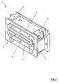
- the lifting device 1 is shown in a basic position. What can be seen is an upper part 2 made of sheet metal, which is connected to the hinge device, and a lower part 3, which is a die-cast part and is connected to the vehicle body.
- the upper and lower parts 2 and 3 are connected to each other on two opposite sides via a deformation element 4.
- Such a metallic deformation element 4 is clearly visible in FIG. 2 , since here the lifting device 1 is shown without the upper part 2.
- the deformation element 4 is a component running in a wave shape in one plane, with an upper and a lower end section 5 and 6, the free ends of which are connected to one another via a narrow web 7.
- the narrow web 7 is designed as a predetermined breaking point.
- the upper end section 5 is fixedly connected to the upper part 2, while the lower end section 6 is fixedly connected to the lower part 3.
- the upper and lower parts 2 and 3 are pressed apart by an actuator.
- the web 7 tears and the two lateral deformation elements 4 are bent apart like an accordion, as shown in FIG. 3 .
- the front flap is now held in the raised position by the bent-apart deformation elements 4 until the pedestrian or cyclist collides with the front flap.
- the front flap is bent in the direction of the impact by the kinetic energy of the impact, and on the other hand, the deformation elements 4 are compressed again.
- the deformation elements 4 thus dampen the impact of the pedestrian or cyclist and help to reduce the risk of injury.
- the exact structure of the lifting device 1 is clear in a longitudinal section, as shown in Fig. 4 .
- the lower part 3 is designed like a trough with a large recess 8 in the middle.
- This recess 8 is closed at the top with a type of piston 9 which in one piece has a circumferential wall 10 which projects slightly at the lower edge.
- This projection 11 is guided laterally in the recess 8.
- a guide pin 12 is attached to the piston 9, which is guided in a suitable bore of the lower part 3.
- the upper part 2, which is not shown in the longitudinal section, is located directly above the piston 9.
- a pyrotechnic ignition cartridge 14 as an actuator projects into the recess 8 from below via a further bore 13.
- the front flap ignites the pyrotechnic cartridge 14.
- the inside The gas volume that arises in the shortest possible time presses on the piston 9 explosively above.
- the piston 9 is over the projection 11 of the circumferential wall 10 in the recess 8 and via the guide pin 12 in the bore in the lower part 3 guided.
- the piston 9 presses on the upper part 2 and lifts it.
- the tears Web 7 of the deformation elements 4 and these are deformed.
- stops 15 are screwed on, which limit the maximum stroke of the piston 9.
- the stroke is effected suddenly by the pyrotechnic ignition cartridge 14 in such a way that the upper part 2 is lifted a little further by the force alone, with the deformation elements 4 being further deformed. This fully raised position is shown in FIG. 5 .
- the front flap is in at least one such lifting device 1 is in a raised position, it can impact a pedestrian or Intercept the cyclist.
- the front flap can yield dent
- the upper and lower parts 2 and 3 of the Lifting device 1 are compressed again.
- the two of them Deformation elements 4 plastically compressed again and take Energy on.
- the lifting height of the front flap is at least partially as Delay path available again.
- the ignition cartridge 14 and the deformation elements 4 are replaced.
Landscapes
- Engineering & Computer Science (AREA)
- Mechanical Engineering (AREA)
- Superstructure Of Vehicle (AREA)
Abstract
Description
- Fig. 1
- eine perspektivische Ansicht einer Anhebevorrichtung einer Frontklappe mit einem integrierten Deformationselement in einer Grundstellung,
- Fig. 2
- eine perspektivische Ansicht der Anhebevorrichtung aus Fig. 1 ohne ein Oberteil,
- Fig. 3
- eine perspektivische Ansicht der Anhebevorrichtung aus Fig. 1 in einer angehobenen Stellung,
- Fig. 4
- einen Längsschnitt durch die Anhebevorrichtung aus Fig. 1 und
- Fig. 5
- einen Längsschnitt durch die Anhebevorrichtung aus Fig. 3.
Claims (7)
- Anordnung einer Frontklappe an einem Fahrzeug, mit zumindest einer Anhebevorrichtung, durch die bei einer detektierten Kollision des Fahrzeugs mit einem Fußgänger oder Radfahrer die Frontklappe gegenüber der geschlossenen Stellung im hinteren und / oder vorderen Bereich angehoben wird, dadurch gekennzeichnet, dass die Anhebevorrichtung (1) mindestens ein Deformationselement (4) aufweist, das sich beim Anheben der Frontklappe plastisch verformt, und das durch die Aufprallenergie des Fußgängers oder Radfahrers auf die angehobene Frontklappe zumindest teilweise wieder zurückverformt werden kann.
- Anordnung nach Anspruch 1, dadurch gekennzeichnet, dass die Anhebevorrichtung (1) zumindest aus einem Ober- und einem Unterteil (3 und 2) besteht, die beim Anheben durch zumindest einen Aktuator (14) auseinander gedrückt werden, wobei das Deformationselement (4) an dem Ober- und dem Unterteil (3 und 2) angebracht ist.
- Anordnung nach Anspruch 1 oder 2, dadurch gekennzeichnet, dass das Deformationselement (4) aus einem U-förmigen Bauteil besteht, das beim Anheben zu einer V-Form aufgebogen wird.
- Anordnung nach Anspruch 1 oder 2, dadurch gekennzeichnet, dass das Deformationselement (4) aus einem wellen- oder zickzackförmigen Bauteil besteht, das beim Anheben ziehharmonikaartig gestreckt wird.
- Anordnung nach Anspruch 3 oder 4, dadurch gekennzeichnet, dass die beiden freien Enden des Deformationselements (4) in der nicht angehobenen Stellung der Anhebevorrichtung (1) mit einem schmalen Steg (7) miteinander verbunden sind, der eine Sollbruchstelle aufweist.
- Anordnung nach einem der Ansprüche 2 bis 5, dadurch gekennzeichnet, dass der Aktuator (14) pyrotechnisch arbeitet.
- Anordnung nach Anspruch 6, dadurch gekennzeichnet, dass der pyrotechnische Aktuator (14) von außen in eine Aussparung (8) des Unterteils (3) hineinragt, die mit einem verlagerbaren Kolben (9) verschlossen ist, wobei der Kolben (9) nach dem Zünden des Aktuators (14) auf das Oberteil (2) drückt und dieses anhebt.
Applications Claiming Priority (2)
| Application Number | Priority Date | Filing Date | Title |
|---|---|---|---|
| DE10308752 | 2003-02-28 | ||
| DE2003108752 DE10308752A1 (de) | 2003-02-28 | 2003-02-28 | Anordnung einer Frontklappe an einem Fahrzeug |
Publications (3)
| Publication Number | Publication Date |
|---|---|
| EP1452408A2 true EP1452408A2 (de) | 2004-09-01 |
| EP1452408A3 EP1452408A3 (de) | 2005-03-16 |
| EP1452408B1 EP1452408B1 (de) | 2006-11-02 |
Family
ID=32748107
Family Applications (1)
| Application Number | Title | Priority Date | Filing Date |
|---|---|---|---|
| EP20040003962 Expired - Lifetime EP1452408B1 (de) | 2003-02-28 | 2004-02-21 | Anordnung einer Frontklappe an einem Fahrzeug |
Country Status (2)
| Country | Link |
|---|---|
| EP (1) | EP1452408B1 (de) |
| DE (2) | DE10308752A1 (de) |
Cited By (1)
| Publication number | Priority date | Publication date | Assignee | Title |
|---|---|---|---|---|
| US7712569B2 (en) * | 2003-06-06 | 2010-05-11 | Magna Electronics Europe Gmbh & Co. Kg | Device and method for raising the hood of a motor vehicle during a collision with a pedestrian |
Families Citing this family (5)
| Publication number | Priority date | Publication date | Assignee | Title |
|---|---|---|---|---|
| DE102005006688A1 (de) * | 2005-02-15 | 2006-08-24 | Bayerische Motoren Werke Ag | Anordnung einer Klappe an einem Fahrzeug |
| DE102005014567A1 (de) * | 2005-03-31 | 2006-10-05 | Bayerische Motoren Werke Ag | Klappenordnung eines Fahrzeugs mit einer Anhebevorrichtung und einer Fixiereinrichtung |
| DE102005034557B9 (de) * | 2005-07-23 | 2009-04-09 | Automotive Group Ise Innomotive Systems Europe Gmbh | Vorrichtung zum Aufstellen der Fronthaube eines Kraftfahrzeuges im Haubenscharnierbereich bei einem drohenden Personenaufprall |
| DE102012109190B4 (de) * | 2012-09-27 | 2014-05-28 | Krauss-Maffei Wegmann Gmbh & Co. Kg | Deformationselement und Verfahren zur Herstellung eines Deformationselements |
| FR3109758B1 (fr) | 2020-04-29 | 2022-09-16 | Autoliv Dev | Dispositif de levée de capot |
Family Cites Families (8)
| Publication number | Priority date | Publication date | Assignee | Title |
|---|---|---|---|---|
| DE19721565B4 (de) * | 1996-05-31 | 2006-10-05 | Volkswagen Ag | Sicherheitseinrichtung an einem Fahrzeug zum Schutz von Fußgängern |
| DE19624328A1 (de) * | 1996-06-18 | 1998-01-08 | Baumann Hans Peter | Aktiver Aufprallschutz für Fahrzeuge |
| DE19957872B4 (de) * | 1999-12-01 | 2010-12-16 | Volkswagen Ag | Sicherheitseinrichtung an einem Fahrzeug zum Schutz von Fußgängern |
| DE19957870A1 (de) * | 1999-12-01 | 2001-06-07 | Volkswagen Ag | Sicherheitseinrichtung an einem Fahrzeug zum Schutz von Fußgängern |
| DE10011944A1 (de) * | 2000-03-11 | 2001-09-13 | Opel Adam Ag | Befestigung eines Aggregats im Motorraum eines Fahrzeuges |
| GB2373218B (en) * | 2001-03-13 | 2004-12-15 | Autoliv Dev | Improvements in or relating to a safety arrangement |
| GB0106175D0 (en) * | 2001-03-13 | 2001-05-02 | Autoliv Dev | Improvements in or relating to a safety arrangement |
| KR100405541B1 (ko) * | 2001-05-18 | 2003-11-14 | 현대자동차주식회사 | 자동차의 후드 힌지구조 |
-
2003
- 2003-02-28 DE DE2003108752 patent/DE10308752A1/de not_active Withdrawn
-
2004
- 2004-02-21 DE DE200450001872 patent/DE502004001872D1/de not_active Expired - Lifetime
- 2004-02-21 EP EP20040003962 patent/EP1452408B1/de not_active Expired - Lifetime
Cited By (1)
| Publication number | Priority date | Publication date | Assignee | Title |
|---|---|---|---|---|
| US7712569B2 (en) * | 2003-06-06 | 2010-05-11 | Magna Electronics Europe Gmbh & Co. Kg | Device and method for raising the hood of a motor vehicle during a collision with a pedestrian |
Also Published As
| Publication number | Publication date |
|---|---|
| EP1452408B1 (de) | 2006-11-02 |
| DE502004001872D1 (de) | 2006-12-14 |
| EP1452408A3 (de) | 2005-03-16 |
| DE10308752A1 (de) | 2004-09-09 |
Similar Documents
| Publication | Publication Date | Title |
|---|---|---|
| EP1549534B1 (de) | Vorrichtung zum schutz von personen bei einem frontalaufprall auf ein kraftfahrzeug | |
| DE10102760B4 (de) | Sicherheitssysteme mit einer aufpralldämpfenden Fronthaube an einem Fahrzeug | |
| EP1293400B1 (de) | Anordnung einer Frontklappe für den Schutz von Fussgängern | |
| EP1238893B1 (de) | Anordnung einer Frontklappe an einem Fahrzeug | |
| WO2005077719A1 (de) | Anordnung einer frontklappe mit verstellhebel an einem fahrzeug | |
| DE10116716A1 (de) | Scharniereinrichtung für eine anhebbare Fronthaube an einem Fahrzeug | |
| WO2005030539A1 (de) | Anordnung einer frontklappe an einem fahrzeug | |
| EP1104728B1 (de) | Sicherheitseinrichtung an einem Fahrzeug zum Schutz von Fussgängern | |
| DE60303356T2 (de) | Kraftfahrzeug und gelenkmechanismus hierfür | |
| DE202015006895U1 (de) | Aufstellbares Klappenscharnier | |
| DE202004002480U1 (de) | Anordnung einer Frontklappe mit Verstellhebel an einem Fahrzeug | |
| EP1452408B1 (de) | Anordnung einer Frontklappe an einem Fahrzeug | |
| EP1743812A2 (de) | Fahrzeugkarosserie mit einer nachgiebig gelagerten Fronthaube | |
| EP1220769A1 (de) | Vorderbau für ein kraftfahrzeug | |
| EP1295762B1 (de) | Anordnung einer Frontklappe an einem Fahrzeug | |
| DE10132950A1 (de) | Sicherheitseinrichtung für Fahrzeuge | |
| EP1293416B1 (de) | Anordnung einer Frontklappe an einem Fahrzeug | |
| WO2005044645A1 (de) | Aktuator für ein aufprallschutzsystem eines fahrzeugs | |
| DE10308140B3 (de) | Vorrichtung zum Schutz von Personen bei einem Frontalaufprall auf ein Kraftfahrzeug | |
| DE10116523C1 (de) | Sicherheitseinrichtung | |
| WO2022013181A1 (de) | Scharnier zur verstellung einer fronthaube von einer normallage in eine schutzlage | |
| DE10200098A1 (de) | Crashaktive Fronthaube an einem Fahrzeug | |
| DE10261860B4 (de) | Crashaktive Fronthaube an einem Fahrzueg | |
| DE102010009064B4 (de) | Verriegelungsanordnung | |
| DE102006043979B4 (de) | Motorhaubenscharnier-Baueinheit für ein Fahrzeug |
Legal Events
| Date | Code | Title | Description |
|---|---|---|---|
| PUAI | Public reference made under article 153(3) epc to a published international application that has entered the european phase |
Free format text: ORIGINAL CODE: 0009012 |
|
| AK | Designated contracting states |
Kind code of ref document: A2 Designated state(s): AT BE BG CH CY CZ DE DK EE ES FI FR GB GR HU IE IT LI LU MC NL PT RO SE SI SK TR |
|
| AX | Request for extension of the european patent |
Extension state: AL LT LV MK |
|
| PUAL | Search report despatched |
Free format text: ORIGINAL CODE: 0009013 |
|
| AK | Designated contracting states |
Kind code of ref document: A3 Designated state(s): AT BE BG CH CY CZ DE DK EE ES FI FR GB GR HU IE IT LI LU MC NL PT RO SE SI SK TR |
|
| AX | Request for extension of the european patent |
Extension state: AL LT LV MK |
|
| 17P | Request for examination filed |
Effective date: 20050803 |
|
| AKX | Designation fees paid |
Designated state(s): DE FR GB IT |
|
| GRAP | Despatch of communication of intention to grant a patent |
Free format text: ORIGINAL CODE: EPIDOSNIGR1 |
|
| GRAS | Grant fee paid |
Free format text: ORIGINAL CODE: EPIDOSNIGR3 |
|
| GRAA | (expected) grant |
Free format text: ORIGINAL CODE: 0009210 |
|
| AK | Designated contracting states |
Kind code of ref document: B1 Designated state(s): DE FR GB IT |
|
| REG | Reference to a national code |
Ref country code: GB Ref legal event code: FG4D Free format text: NOT ENGLISH |
|
| REF | Corresponds to: |
Ref document number: 502004001872 Country of ref document: DE Date of ref document: 20061214 Kind code of ref document: P |
|
| GBT | Gb: translation of ep patent filed (gb section 77(6)(a)/1977) |
Effective date: 20061207 |
|
| ET | Fr: translation filed | ||
| PLBE | No opposition filed within time limit |
Free format text: ORIGINAL CODE: 0009261 |
|
| STAA | Information on the status of an ep patent application or granted ep patent |
Free format text: STATUS: NO OPPOSITION FILED WITHIN TIME LIMIT |
|
| 26N | No opposition filed |
Effective date: 20070803 |
|
| REG | Reference to a national code |
Ref country code: FR Ref legal event code: PLFP Year of fee payment: 12 |
|
| PGFP | Annual fee paid to national office [announced via postgrant information from national office to epo] |
Ref country code: DE Payment date: 20150304 Year of fee payment: 12 Ref country code: IT Payment date: 20150228 Year of fee payment: 12 |
|
| PGFP | Annual fee paid to national office [announced via postgrant information from national office to epo] |
Ref country code: FR Payment date: 20150226 Year of fee payment: 12 Ref country code: GB Payment date: 20150226 Year of fee payment: 12 |
|
| REG | Reference to a national code |
Ref country code: DE Ref legal event code: R119 Ref document number: 502004001872 Country of ref document: DE |
|
| GBPC | Gb: european patent ceased through non-payment of renewal fee |
Effective date: 20160221 |
|
| REG | Reference to a national code |
Ref country code: FR Ref legal event code: ST Effective date: 20161028 |
|
| PG25 | Lapsed in a contracting state [announced via postgrant information from national office to epo] |
Ref country code: IT Free format text: LAPSE BECAUSE OF NON-PAYMENT OF DUE FEES Effective date: 20160221 |
|
| PG25 | Lapsed in a contracting state [announced via postgrant information from national office to epo] |
Ref country code: GB Free format text: LAPSE BECAUSE OF NON-PAYMENT OF DUE FEES Effective date: 20160221 Ref country code: FR Free format text: LAPSE BECAUSE OF NON-PAYMENT OF DUE FEES Effective date: 20160229 Ref country code: DE Free format text: LAPSE BECAUSE OF NON-PAYMENT OF DUE FEES Effective date: 20160901 |