EP1452437B2 - Moyeu d'entraînement pour bicyclette - Google Patents
Moyeu d'entraînement pour bicyclette Download PDFInfo
- Publication number
- EP1452437B2 EP1452437B2 EP03004518A EP03004518A EP1452437B2 EP 1452437 B2 EP1452437 B2 EP 1452437B2 EP 03004518 A EP03004518 A EP 03004518A EP 03004518 A EP03004518 A EP 03004518A EP 1452437 B2 EP1452437 B2 EP 1452437B2
- Authority
- EP
- European Patent Office
- Prior art keywords
- clutch
- hub
- drive member
- pawl
- way clutch
- Prior art date
- Legal status (The legal status is an assumption and is not a legal conclusion. Google has not performed a legal analysis and makes no representation as to the accuracy of the status listed.)
- Expired - Lifetime
Links
- 230000005540 biological transmission Effects 0.000 title claims abstract description 67
- 230000033001 locomotion Effects 0.000 claims abstract description 9
- 230000000712 assembly Effects 0.000 description 2
- 238000000429 assembly Methods 0.000 description 2
- 230000000295 complement effect Effects 0.000 description 2
- 238000010276 construction Methods 0.000 description 1
- 230000002093 peripheral effect Effects 0.000 description 1
Images

Classifications
-
- B—PERFORMING OPERATIONS; TRANSPORTING
- B62—LAND VEHICLES FOR TRAVELLING OTHERWISE THAN ON RAILS
- B62M—RIDER PROPULSION OF WHEELED VEHICLES OR SLEDGES; POWERED PROPULSION OF SLEDGES OR SINGLE-TRACK CYCLES; TRANSMISSIONS SPECIALLY ADAPTED FOR SUCH VEHICLES
- B62M11/00—Transmissions characterised by the use of interengaging toothed wheels or frictionally-engaging wheels
- B62M11/04—Transmissions characterised by the use of interengaging toothed wheels or frictionally-engaging wheels of changeable ratio
- B62M11/14—Transmissions characterised by the use of interengaging toothed wheels or frictionally-engaging wheels of changeable ratio with planetary gears
- B62M11/16—Transmissions characterised by the use of interengaging toothed wheels or frictionally-engaging wheels of changeable ratio with planetary gears built in, or adjacent to, the ground-wheel hub
Definitions
- the present invention relates to a hub transmission for a bicycle, also referred to as an internal hub transmission. More particularly, the hub transmission comprises a movable clutch member which is actuated to select the gear speed.
- Internal hub transmissions generally comprise a hub axle fixed to a bicycle frame and a hub body rotatable about the hub axle.
- a planetary gear mechanism is housed within the hub body by which rotational drive force can be communicated to the hub body through various transmission paths defined by the planetary gear mechanism.
- a clutch mechanism including a clutch member is provided for selecting the transmission path by selected axial movement of the clutch member, for example by a push rod.
- a hub transmission of the above type is disclosed in the European patent application EP 0 876 953 , where additional means are provided for facilitating actuation of the clutch member.
- the drive member is always in engagement with the clutch member regardless of the gear speed engaged, for example high speed, medium speed or low speed.
- the gear speed engaged for example high speed, medium speed or low speed.
- the backward rotation of the drive member is always accompanied with backward rotation of the clutch member.
- the high speed gear is selected, not only the clutch member but also the planetary gear carrier is also rotated backwardly when back pedaling is performed.
- the clutch member and in some cases parts of the planetary gear mechanism are also rotated backwardly, reverse rotation is not smooth and somewhat heavy.
- An object of the present invention is therefore to provide an improved hub transmission, which allows a smooth and light reverse running of the drive member and therefore of the transmission when back pedaling.
- a further object is to provide a hub transmission with internal gear changing means, where additionally external speed changing is allowed through chain shifting.
- a hub transmission is provided as defined in claim 1.
- a drive member is provided to be rotatably mounted around a hub axle.
- a hub body is also mounted to rotate about the hub axle, where a planetary gear mechanism is provided for communicating forward rotational force from the drive member to the hub body through various force transmission paths.
- the planetary gear mechanism includes a planet gear supported by a planet gear carrier for rotation around the hub axle, a ring gear engaging the planet gear and a sun gear disposed on the hub axle.
- a clutch member is provided to be movable in axial direction of the axle.
- a pawl body is arranged between the drive member and the clutch member.
- a first one-way clutch is arranged to transmit forward rotational drive force from the drive member to the pawl body.
- the drive member always engages the clutch member through the first one-way clutch to transmit forward rotational motion to the clutch member in any one of the selected gear speeds.
- the first one-way clutch decouples the drive member from the clutch member when reverse rotational motion is applied to the drive member through back pedaling.
- This is advantageously achieved according to the present invention by providing a pawl body between the drive member and the clutch member, where the first one-way clutch is preferably arranged on the pawl body. Consequently, the drive member runs smoothly and lightly when back pedaling because the internal components of the hub transmission are substantially decoupled from the drive member. A smooth backward running of the hub transmission can therefore be achieved which is nearly as light as for example a free hub commonly used with a derailleur.
- the clutch member is provided with teeth or a spline on an outer periphery, which is arranged to be slidably engageable with serrations on an inner periphery of the pawl body. In this manner, the clutch member maintains its connection to the pawl body regardless of the axial position of the clutch member.
- the first one-way clutch comprises at least one pawl mounted on an outer periphery of the pawl body, where complementary ratchet teeth are formed on an inner periphery of the drive member.
- the at least one pawl is pivotally mounted and spring biased so as to engage with the ratchet teeth when forward rotational drive force is applied to the drive member.
- the ratchet teeth are arranged to disengage from the at least one pawl when reverse rotational drive force is applied to the drive member.
- a second one-way clutch is arranged between the pawl body and the ring gear of the planetary gear mechanism for transmitting only forward rotational force to the ring gear.
- the second one-way clutch comprises at least two pawls pivotally mounted on an outer periphery of the pawl body. These pawls are preferably spring biased to engage with complementary ratchet teeth formed on an inner periphery of the ring gear. The arrangement allows a constructively convenient transmission of forward rotational drive force from the drive member through the pawl body to the ring gear, while at the same time reverse rotational drive force is not transmitted to the ring gear.
- a third one-way clutch is provided between the ring gear and the hub body, the third one-way clutch being switchable between a power transmission state in which the third one-way clutch engages ratchet teeth of the hub body and a power interruption state in which the third one-way clutch disengages from the ratchet teeth of the hub body.
- the clutch member comprises a switching portion for switching the third one-way clutch between the power transmission state and power interruption state depending on the axial position of the clutch member.
- the clutch member is also engageable with the planet gear carrier for defining a transmission path through the clutch member to the planet gear carrier for the high speed transmission path.
- the end of the clutch member opposing the drive member is provided with engaging teeth for engagement with serration teeth on a periphery of the planet gear carrier.
- the outer periphery of the drive member is adapted for mounting at least one sprocket.
- the outer periphery has an axial extension so as to allow mounting of several chain sprockets.
- the present hub transmission can be employed in a combination where a drive chain is shifted from one sprocket to another sprocket to provide an external speed change.
- gear speed change can be undertaken internally in the present hub transmission.
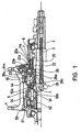
- Fig. 1 shows an embodiment of the present hub transmission with the clutch member engaged to select the high speed transmission path.
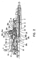
- Fig. 2 shows the embodiment of Fig. 1 , where the clutch member is axially positioned for engagement of the normal speed transmission path.
- Fig. 3 shows the embodiment of Fig. 1 , where the clutch member is axially positioned for engagement of the low speed transmission path.
- FIG. 1 an embodiment of the hub transmission is shown with a hub axle 2 adapted to be fixed to the rear drop-out (not shown) of the frame body of a bicycle.
- a drive member 11 is disposed around and rotatably mounted on the outer periphery at one end of the hub axle 2.
- a hub body 4 is rotatably mounted to the hub axle 2 and a planetary gear mechanism 5 is housed in the hub body 4.
- a clutch control mechanism 25 provides means for selecting the power transmission path through axial adjustment of the clutch member 26.
- the hub axle 2 is a cylinder member with a larger diameter at its center and a smaller diameter at both ends.
- the center of the axle 2 is provided with a bore for disposition of a control rod 3.
- the control rod 3 is activated at the right end in Fig. 1 through actuator means controlled by a shift control cable (not shown).
- Axial movement of the control rod 3 is transmitted through the shift key 7, which extends through an axial groove of the hub axle.
- the shift key 7 engages with the clutch member 26, whereby the axial positioning of the clutch member 26 for selection of the force transmission path is accomplished.
- the drive member 11 is rotatably supported on the hub axle 2 by means of a ball bearing assembly 8.
- the hub body 4 is also mounted in ball bearing assemblies for rotation about the hub axle 2 and includes radially outward extending flanges for supporting spokes (not shown) for fixation to a bicycle wheel.
- the planetary gear mechanism 5 comprises a sun gear formed on the hub axle, a planet gear carrier 52 rotatably mounted on the outer periphery of the hub axle 2, and normally three planet gears 51 (only one planet gear is shown in Fig. 1 ).
- the planet gears mesh with the sun gear as well as with an inner periphery of a ring gear 34.
- the planet gear carrier 52 is provided with serration teeth 52a formed on a periphery, preferably an inner periphery, of the planet gear carrier 52 at an end facing the drive member 11.
- the serration teeth 52a are provided for engagement with corresponding engaging serration teeth 26b of the clutch member 26, as will be discussed below.
- a first one-way clutch 20 is arranged between the drive member 11 and a pawl body 22.
- the first one-way clutch comprises at least one pawl 20a mounted on an outer periphery of the pawl body 22.
- One pawl is sufficient for rotational force transmission, however two or more pawls may be provided if desired.
- the pawls 20a are pivotally mounted on an outer periphery of the pawl body 22 and are spring biased so as to engage with ratchet teeth 11a on an inner periphery of the drive member 11.
- the ratchet teeth 11a are formed in a manner that forward rotational drive force applied to the drive member 11 is transferred to the pawl body 22, whereas the pawls 20a disengage from the ratchet teeth 11a when reverse rotational force is present on the drive member, for example when back pedaling.
- a second one-way clutch 23 is arranged between the pawl body 22 and the ring gear 34 as is seen in Fig. 1 .
- the second one-way clutch 23 comprises at least two pawls 23a which are pivotally mounted on an outer periphery of the pawl body 22.
- the pawls 23a are spring biased to engage with ratchet teeth 34a formed on an inner periphery of the ring gear 34.
- two pawls 23a are employed, while in practice four pawls or more may be provided depending on the situation, i.e. depending on the force to be transferred.
- the ring gear 34 remains fixed in axial direction, while being rotatably mounted about the axle 2.
- the ring gear 34 extends from a position of the planet gears 51 at one end (left side in Fig. 1 ) to a position adjacent to the drive member 11 at the other end.
- inner peripheral teeth are provided which mesh with the planet gears 51.
- the ring gear 34 is also provided with a third one-way clutch 35 which comprises at least one clutch pawl 35a, which is biased in the standing or erected position by a coil spring.
- the clutch pawl or pawls 35a engage with ratchet teeth 4a on an inner periphery of the hub body 4.
- the clutch pawl 35a meshes with the ratchet teeth 4a when the ring gear is rotated in the forward drive direction.
- the clutch pawl or pawls 35a can be placed in a power transmission state or a power interruption as will be discussed below.
- the clutch pawl 35a In the power transmission state, forward drive rotation is transferred from the ring gear to the pawl 35a and the ratchet teeth 4a to the hub body 4.
- the clutch pawl 35a is knocked down by a switching portion 26c of the clutch member 26 as shown in Fig. 3 . In this power interruption state, no forward or reverse rotational drive force can be transmitted to the ratchet teeth 4a of the hub body.
- Fig. 1 shows the high speed transmission path.
- Forward rotational force applied to the drive member 11 is transmitted through the one-way clutch 20 to the pawl body 22 which in turn transmits the force to the clutch member 26 via the serration teeth 26a.
- the clutch member 26 has been placed by the clutch control mechanism 25 in an axial position to the left in Fig. 1 . In this position, the engaging serration teeth 26b of the clutch member engage with the serration teeth 52a on the planet gear carrier 52. Rotation is then transmitted from the planet gear carrier 52 via the planet gear mechanism 5 to the ring gear 34 and subsequently to the third one-way clutch 35 which is in the erected state, i.e. in the power transmission state. Finally, the one-way clutch 35 transfers the forward drive force to the hub body 4.
- the input rotation is increased in speed and then output according to the gear ratio determined by the numbers of teeth on the sun gear, the planet gears 51 and the ring gear 34.
- forward rotation of the drive member 11 is also transmitted to the second one-way clutch 23, however the rotation of the ring gear 34 is faster than that of the drive member 11, so that no rotation is transmitted to the ring gear 34 via the second one-way clutch 23.
- the normal speed operating condition is illustrated in Fig. 2 .
- the clutch member 26 is positioned by means of the clutch control mechanism 25 to an intermediate axial position. Forward drive rotation from the drive member 11 is transmitted through the one-way clutch 20 to the pawl body 22 and then through the second one-way clutch 23 directly to the ring gear 34.
- the third one-way clutch 35 is still in the power transmission state so that the forward rotational drive force of the ring gear 34 is transmitted directly to the hub body 4.
- the forward rotational drive force of the ring gear 34 is also transmitted to the planet gear carrier 52 via the planet gears 51 and from there to a roller 57 which engages the hub cap 56.
- the hub cap 56 is fixed to the hub body 4 and acts as a further transmission means of rotational force to the hub body 4.
- the rotational speed of the planet gear carrier 52 is reduced by the planet gears 51 so that rotational transmission through the roller 57 and the hub cap 56 is overrun by the faster rotational motion of the third one-way clutch 35.
- Fig. 3 illustrates the low-speed transmission path, where the clutch member 26 is now positioned axially to the right hand side in the direction of the drive member 11.
- a switching portion 26c of the clutch member 26 has engaged with the clutch pawls 35a to place them in the knocked down state, i.e. the third one-way clutch 35 is in the power interruption state.
- the forward rotation of the drive member 11 is transmitted through the one-way clutch 20 to the pawl body 22 and from there through the second one-way clutch 23 to the ring gear 34.
- the one-way clutch 35 is knocked down, so that no rotation is transmitted to the hub body at this position.
- the forward rotation of the ring gear is then transmitted through the planet gear mechanism 5 to the planet gear carrier 52 and from there through the roller 57 and the hub cap 56 to the hub body 4.
- the rotation speed of the ring gear 34 is reduced by the planet gears 51 resulting in the low speed transmission condition.
- a particular advantage of the present invention is that the outer periphery of the drive member 11, for example as shown in Fig. 1 , can be provided with an axial extension to allow several chain sprockets (not shown) to be secured to the outer periphery.
- chain shifting means which would allow changing speeds by shifting the chain from one sprocket to another.
- An advantageous application of the present hub transmission is then a combination of the present hub transmission with multi-stage sprocket assembly mounted to the drive member 11 to form a combined speed changing apparatus for a bicycle.
- the present hub transmission is advantageously adapted for such an apparatus, since the provision of the pawl body 22 and the first one-way clutch 20 allow a smooth and light running of the drive member 11, especially in reverse rotation. In such an apparatus, the smooth running of the present drive member 11 would be comparable to that normally achieved in a freewheel arrangement commonly used in multi-stage sprocket assemblies.
Landscapes
- Engineering & Computer Science (AREA)
- Chemical & Material Sciences (AREA)
- Combustion & Propulsion (AREA)
- Transportation (AREA)
- Mechanical Engineering (AREA)
- Structure Of Transmissions (AREA)
- Transmission Devices (AREA)
- Axle Suspensions And Sidecars For Cycles (AREA)
- Steering Devices For Bicycles And Motorcycles (AREA)
- Fittings On The Vehicle Exterior For Carrying Loads, And Devices For Holding Or Mounting Articles (AREA)
Claims (12)
- Transmission à moyeu interne pour bicyclette comprenant :un élément d'entraînement (11) monté de manière rotative autour d'un essieu (2) de moyeu ;un corps de moyeu (4) monté de manière rotative autour de l'essieu (2) de moyeu ;un mécanisme d'engrenages planétaires (5) couplé pour communiquer la force de rotation de l'élément d'entraînement (11) au corps de moyeu (4) par différents passages de transmission de force, ledit mécanisme d'engrenages planétaires (5) comprenant une roue planétaire (51) supportée par un support de roue planétaire (52) pour la rotation autour de l'essieu (2) de moyeu et une couronne (34) mettant en prise la roue planétaire (51) ;un élément d'embrayage (26) mobile dans la direction axiale (X) de l'essieu (2) ;caractérisée en ce que :un corps de cliquet (22) est agencé entre l'élément d'entraînement (11) et l'élément d'embrayage (26), etune première roue libre (20) est agencée pour transmettre la force d'entraînement rotationnelle avant de l'élément d'entraînement (11) au corps de cliquet (22),où l'élément d'entraînement (11) met toujours en prise l'élément d'embrayage (26) via la première roue libre (20) pour transmettre un mouvement rotationnel avant à l'élément d'embrayage (26) dans l'une quelconque des vitesses de développement choisies, et où la première roue libre (20) découple l'élément d'entraînement (11) de l'élément d'embrayage (26) quand un mouvement rotationnel inverse est appliqué à l'élément d'entraînement (11) par rétropédalage.
- Transmission à moyeu interne selon la revendication 1, dans laquelle l'élément d'embrayage (26) est prévu, au niveau d'une extrémité vers l'élément d'entraînement (11), avec des dents dentelées (26a) sur sa périphérie externe, afin de pouvoir se mettre en prise de manière coulissante avec les dents dentelées (22a) sur une périphérie interne du corps de cliquet (22).
- Transmission à moyeu interne selon la revendication 1 ou 2, dans laquelle la première roue libre (20) comprend au moins un cliquet (20a) monté sur une périphérie externe dudit corps de cliquet (22) et des dents triangulaires (11a) formées sur une périphérie interne de l'élément d'entraînement (11).
- Transmission à moyeu interne selon la revendication 3, dans laquelle ledit au moins un cliquet (20a) est monté de manière pivotante et sollicité par ressort afin de se mettre en prise avec lesdites dents triangulaires (11a) lorsque la force d'entraînement rotationnelle avant est appliquée sur ledit élément d'entraînement (11) et afin de se dégager desdites dents triangulaires (11a) lorsque la force d'entraînement rotationnelle inverse est appliquée sur ledit élément d'entraînement (11).
- Transmission à moyeu interne selon l'une quelconque des revendications 1 à 4, dans laquelle une seconde roue libre (23) est agencée entre ledit corps de cliquet (22) et ladite couronne (34) pour ne transmettre que la force d'entraînement rotationnelle avant dudit corps de cliquet (22) à ladite couronne (34).
- Transmission à moyeu interne selon la revendication 5, dans laquelle ladite seconde roue libre (23) comprend au moins deux cliquets (23a) montés de manière pivotante sur une périphérie externe dudit corps de cliquet (22), lesdits au moins deux cliquets (23a) étant sollicités par ressort pour mettre en prise les dents triangulaires (34a) formées sur une périphérie interne de ladite couronne (34).
- Transmission à moyeu interne selon l'une quelconque des revendications 1 à 6, dans laquelle une troisième roue libre (35) est agencée entre ladite couronne (34) et ledit corps de moyeu (4), ladite troisième roue libre (35) comprenant au moins un cliquet (35a) d'embrayage monté de manière pivotante sur ladite couronne (34) et des dents triangulaires (4a) prévues sur une périphérie interne dudit corps de moyeu (4).
- Transmission à moyeu interne selon la revendication 7, dans laquelle ledit au moins un cliquet (35a) d'embrayage est commutable entre un état de transmission de puissance dans lequel ledit au moins un cliquet (35a) d'embrayage est vertical et se met en prise avec lesdites dents triangulaires (4a) dudit corps de moyeu (4) pour la transmission de la force rotationnelle avant et un état d'interruption de puissance dans lequel ledit au moins un cliquet (35a) d'embrayage est renversé et ne se met pas en prise avec lesdites dents triangulaires (4a) du corps de moyeu (4).
- Transmission à moyeu interne selon la revendication 8, dans laquelle ledit élément d'embrayage (26) comprend une partie de commutation (26c) pour commuter ledit au moins un cliquet (35a) d'embrayage entre ledit état de transmission de puissance et ledit état d'interruption de puissance en fonction de la position axiale de l'élément d'embrayage (26) sur l'essieu (2) du moyeu.
- Transmission à moyeu interne selon l'une quelconque des revendications 1 à 9, dans laquelle ledit élément d'embrayage (26) est prévu, au niveau d'une extrémité opposée audit élément d'entraînement (11), avec des dents dentelées de mise en prise (26b) pour la mise en prise avec des dents dentelées (52a) situées sur une périphérie du support de roue planétaire (52).
- Transmission à moyeu interne selon l'une quelconque des revendications 1 à 10, dans laquelle la périphérie externe de l'élément d'entraînement (11) est adaptée pour le montage d'au moins un pignon.
- Dispositif de changement de vitesse pour bicyclette comprenant la transmission à moyeu selon l'une quelconque des revendication 1 à 11 avec un ensemble de pignons à plusieurs étages monté au niveau d'une périphérie externe de l'élément d'entraînement (11).
Priority Applications (8)
| Application Number | Priority Date | Filing Date | Title |
|---|---|---|---|
| DE60301483T DE60301483T3 (de) | 2003-02-28 | 2003-02-28 | Antriebsnabe für ein Fahrrad |
| AT03004518T ATE303288T1 (de) | 2003-02-28 | 2003-02-28 | Antriebsnabe für ein fahrrad |
| EP03004518A EP1452437B2 (fr) | 2003-02-28 | 2003-02-28 | Moyeu d'entraînement pour bicyclette |
| EP03016004A EP1452438B1 (fr) | 2003-02-28 | 2003-07-14 | Moyeu d'entraînement pour bicyclette |
| US10/707,833 US7083542B2 (en) | 2003-02-28 | 2004-01-15 | Internal bicycle hub transmission with a one-way clutch for a driving member |
| JP2004029768A JP4006405B2 (ja) | 2003-02-28 | 2004-02-05 | 自転車用内装変速ハブおよび自転車用変速機 |
| CN200510125094.6A CN1807179B (zh) | 2003-02-28 | 2004-02-17 | 用于自行车的轮毂变速器及变速设备 |
| CNB200410005213XA CN100406341C (zh) | 2003-02-28 | 2004-02-17 | 用于自行车的轮毂内变速器 |
Applications Claiming Priority (1)
| Application Number | Priority Date | Filing Date | Title |
|---|---|---|---|
| EP03004518A EP1452437B2 (fr) | 2003-02-28 | 2003-02-28 | Moyeu d'entraînement pour bicyclette |
Publications (3)
| Publication Number | Publication Date |
|---|---|
| EP1452437A1 EP1452437A1 (fr) | 2004-09-01 |
| EP1452437B1 EP1452437B1 (fr) | 2005-08-31 |
| EP1452437B2 true EP1452437B2 (fr) | 2009-06-17 |
Family
ID=32748828
Family Applications (1)
| Application Number | Title | Priority Date | Filing Date |
|---|---|---|---|
| EP03004518A Expired - Lifetime EP1452437B2 (fr) | 2003-02-28 | 2003-02-28 | Moyeu d'entraînement pour bicyclette |
Country Status (4)
| Country | Link |
|---|---|
| EP (1) | EP1452437B2 (fr) |
| CN (1) | CN1807179B (fr) |
| AT (1) | ATE303288T1 (fr) |
| DE (1) | DE60301483T3 (fr) |
Families Citing this family (5)
| Publication number | Priority date | Publication date | Assignee | Title |
|---|---|---|---|---|
| DE602005003547T2 (de) | 2005-01-27 | 2008-10-23 | Shimano Inc., Sakai | Fahrradantriebsnabe |
| US8357071B2 (en) * | 2010-03-29 | 2013-01-22 | Shimano Inc. | Planetary gear mechanism for a bicycle internal hub transmission |
| JP6302870B2 (ja) * | 2015-05-29 | 2018-03-28 | 株式会社シマノ | 変速機 |
| CN106949199B (zh) * | 2017-05-11 | 2023-09-22 | 张家港川梭车业有限公司 | 一种双轮驱动棘爪移动式换挡二挡变速装置 |
| NL2032278B1 (en) * | 2022-06-24 | 2024-01-09 | Classified Cycling Bv | Hub assembly for a bicycle |
Citations (11)
| Publication number | Priority date | Publication date | Assignee | Title |
|---|---|---|---|---|
| GB190703414A (en) † | 1907-02-11 | 1908-02-11 | Rudge Whitworth Ltd | Improvements in and relating to Variable Speed Epicyclic Gears |
| GB190717726A (en) † | 1907-08-03 | 1908-06-04 | Robert Allen Cordner | Improvements in and relating to Variable Speed Driving Mechanism |
| DE1097304B (de) † | 1958-02-24 | 1961-01-12 | Fritz K Zapletal | Selbstschaltendes Wechselgetriebe fuer Fahrraeder, motorisch betriebene Fahrzeuge aller Art und Landmaschinen od. dgl. |
| US3366206A (en) † | 1965-06-15 | 1968-01-30 | Shimano Industrial Co | Bicycle hub having a built-in three-stage speed change mechanism equipped with a coaster brake |
| US3432013A (en) † | 1966-07-05 | 1969-03-11 | Shimano Industrial Co | Rear hub with built-in three stage speed change mechanism for a bicycle |
| US3492883A (en) † | 1967-12-14 | 1970-02-03 | Tetsuo Maeda | Driving chain gear of a bicycle |
| DE8328318U1 (de) † | 1983-10-01 | 1984-02-23 | Fichtel & Sachs Ag, 8720 Schweinfurt | Antriebsnabe fuer fahrraeder od. dgl. |
| GB2166503A (en) † | 1984-11-02 | 1986-05-08 | Fichtel & Sachs Ag | Multi-speed gear hub for a bicycle |
| US4674617A (en) † | 1983-04-25 | 1987-06-23 | Shimano Industrial Company Limited | Freewheel for a bicycle |
| EP0693419A2 (fr) † | 1994-07-23 | 1996-01-24 | FICHTEL & SACHS AG | Transmission de bicyclette à plusieurs vitesses avec plus de trois vitesses |
| DE10134842A1 (de) † | 2001-07-17 | 2003-02-06 | Sram De Gmbh | Lastschaltbare Mehrgangnabe |
Family Cites Families (7)
| Publication number | Priority date | Publication date | Assignee | Title |
|---|---|---|---|---|
| GB1555532A (en) * | 1975-07-10 | 1979-11-14 | Shimano Industrial Co | Unit hub for a giycle |
| DE2940841A1 (de) * | 1979-10-09 | 1981-04-23 | Fichtel & Sachs Ag, 8720 Schweinfurt | Kombinierte mehrgang-schaltung fuer antriebsnabe fuer fahrraeder o.dgl. |
| JP3044192B2 (ja) * | 1996-04-22 | 2000-05-22 | 株式会社シマノ | 内装ハブ |
| JP2983173B2 (ja) * | 1996-04-22 | 1999-11-29 | 株式会社シマノ | 内装ハブ |
| JP3142246B2 (ja) * | 1997-05-08 | 2001-03-07 | 株式会社シマノ | 自転車用内装変速ハブ |
| DE19915436C2 (de) * | 1999-04-06 | 2001-03-15 | Ulrich Fahl | Antriebsnabe |
| US6409281B1 (en) * | 2000-12-04 | 2002-06-25 | Shimano Inc. | Bicycle hub with spacer and detachable freewheel |
-
2003
- 2003-02-28 DE DE60301483T patent/DE60301483T3/de not_active Expired - Lifetime
- 2003-02-28 EP EP03004518A patent/EP1452437B2/fr not_active Expired - Lifetime
- 2003-02-28 AT AT03004518T patent/ATE303288T1/de not_active IP Right Cessation
-
2004
- 2004-02-17 CN CN200510125094.6A patent/CN1807179B/zh not_active Expired - Fee Related
Patent Citations (11)
| Publication number | Priority date | Publication date | Assignee | Title |
|---|---|---|---|---|
| GB190703414A (en) † | 1907-02-11 | 1908-02-11 | Rudge Whitworth Ltd | Improvements in and relating to Variable Speed Epicyclic Gears |
| GB190717726A (en) † | 1907-08-03 | 1908-06-04 | Robert Allen Cordner | Improvements in and relating to Variable Speed Driving Mechanism |
| DE1097304B (de) † | 1958-02-24 | 1961-01-12 | Fritz K Zapletal | Selbstschaltendes Wechselgetriebe fuer Fahrraeder, motorisch betriebene Fahrzeuge aller Art und Landmaschinen od. dgl. |
| US3366206A (en) † | 1965-06-15 | 1968-01-30 | Shimano Industrial Co | Bicycle hub having a built-in three-stage speed change mechanism equipped with a coaster brake |
| US3432013A (en) † | 1966-07-05 | 1969-03-11 | Shimano Industrial Co | Rear hub with built-in three stage speed change mechanism for a bicycle |
| US3492883A (en) † | 1967-12-14 | 1970-02-03 | Tetsuo Maeda | Driving chain gear of a bicycle |
| US4674617A (en) † | 1983-04-25 | 1987-06-23 | Shimano Industrial Company Limited | Freewheel for a bicycle |
| DE8328318U1 (de) † | 1983-10-01 | 1984-02-23 | Fichtel & Sachs Ag, 8720 Schweinfurt | Antriebsnabe fuer fahrraeder od. dgl. |
| GB2166503A (en) † | 1984-11-02 | 1986-05-08 | Fichtel & Sachs Ag | Multi-speed gear hub for a bicycle |
| EP0693419A2 (fr) † | 1994-07-23 | 1996-01-24 | FICHTEL & SACHS AG | Transmission de bicyclette à plusieurs vitesses avec plus de trois vitesses |
| DE10134842A1 (de) † | 2001-07-17 | 2003-02-06 | Sram De Gmbh | Lastschaltbare Mehrgangnabe |
Also Published As
| Publication number | Publication date |
|---|---|
| EP1452437A1 (fr) | 2004-09-01 |
| ATE303288T1 (de) | 2005-09-15 |
| DE60301483T3 (de) | 2009-11-19 |
| EP1452437B1 (fr) | 2005-08-31 |
| DE60301483T2 (de) | 2006-06-29 |
| DE60301483D1 (de) | 2005-10-06 |
| CN1807179B (zh) | 2010-05-05 |
| CN1807179A (zh) | 2006-07-26 |
Similar Documents
| Publication | Publication Date | Title |
|---|---|---|
| EP2272744B1 (fr) | Moyeu à engrenages internes pour bicyclette | |
| US5540456A (en) | Multispeed hub for a bicycle | |
| EP1132287B1 (fr) | Moyeu d'entraînement de bicyclette | |
| EP1452438B1 (fr) | Moyeu d'entraînement pour bicyclette | |
| EP1323627B1 (fr) | Moyeu d'entraînement de bicyclette avec mécanisme de commande pour dispositif d'assistance au changement de vitesse | |
| EP1980483B1 (fr) | Système d'assemblage pour transmission de bicyclette interne | |
| EP2062810B1 (fr) | Transmission à moyeu pour bicyclette avec un mécanisme de contrôle de puissance pour un mécanisme assisté | |
| EP2020374B1 (fr) | Ensemble de moyeu de transmission interne | |
| JP2914909B2 (ja) | 自転車用変速装置内装ハブ | |
| US6312355B1 (en) | Bicycle transmission that shifts when a driver is in a predetermined rotational position | |
| EP1323626A2 (fr) | Porte-satellites à elements multiples pour moyeu d'entraínement de bicyclette | |
| GB2466574A (en) | Fixed gear bicycle hub | |
| EP1112922B1 (fr) | Moyeu d'entraînement de bicyclette | |
| EP1452437B2 (fr) | Moyeu d'entraînement pour bicyclette | |
| EP1686055B1 (fr) | Moyeu d'entraînement de bicyclette | |
| TWI254013B (en) | An internal hub transmission for a bicycle |
Legal Events
| Date | Code | Title | Description |
|---|---|---|---|
| PUAI | Public reference made under article 153(3) epc to a published international application that has entered the european phase |
Free format text: ORIGINAL CODE: 0009012 |
|
| AK | Designated contracting states |
Kind code of ref document: A1 Designated state(s): AT BE BG CH CY CZ DE DK EE ES FI FR GB GR HU IE IT LI LU MC NL PT SE SI SK TR |
|
| AX | Request for extension of the european patent |
Extension state: AL LT LV MK RO |
|
| 17P | Request for examination filed |
Effective date: 20040906 |
|
| GRAP | Despatch of communication of intention to grant a patent |
Free format text: ORIGINAL CODE: EPIDOSNIGR1 |
|
| AKX | Designation fees paid |
Designated state(s): AT BE BG CH CY CZ DE DK EE ES FI FR GB GR HU IE IT LI LU MC NL PT SE SI SK TR |
|
| GRAS | Grant fee paid |
Free format text: ORIGINAL CODE: EPIDOSNIGR3 |
|
| GRAA | (expected) grant |
Free format text: ORIGINAL CODE: 0009210 |
|
| AK | Designated contracting states |
Kind code of ref document: B1 Designated state(s): AT BE BG CH CY CZ DE DK EE ES FI FR GB GR HU IE IT LI LU MC NL PT SE SI SK TR |
|
| PG25 | Lapsed in a contracting state [announced via postgrant information from national office to epo] |
Ref country code: LI Free format text: LAPSE BECAUSE OF FAILURE TO SUBMIT A TRANSLATION OF THE DESCRIPTION OR TO PAY THE FEE WITHIN THE PRESCRIBED TIME-LIMIT Effective date: 20050831 Ref country code: FI Free format text: LAPSE BECAUSE OF FAILURE TO SUBMIT A TRANSLATION OF THE DESCRIPTION OR TO PAY THE FEE WITHIN THE PRESCRIBED TIME-LIMIT Effective date: 20050831 Ref country code: AT Free format text: LAPSE BECAUSE OF FAILURE TO SUBMIT A TRANSLATION OF THE DESCRIPTION OR TO PAY THE FEE WITHIN THE PRESCRIBED TIME-LIMIT Effective date: 20050831 Ref country code: SK Free format text: LAPSE BECAUSE OF FAILURE TO SUBMIT A TRANSLATION OF THE DESCRIPTION OR TO PAY THE FEE WITHIN THE PRESCRIBED TIME-LIMIT Effective date: 20050831 Ref country code: SI Free format text: LAPSE BECAUSE OF FAILURE TO SUBMIT A TRANSLATION OF THE DESCRIPTION OR TO PAY THE FEE WITHIN THE PRESCRIBED TIME-LIMIT Effective date: 20050831 Ref country code: BE Free format text: LAPSE BECAUSE OF FAILURE TO SUBMIT A TRANSLATION OF THE DESCRIPTION OR TO PAY THE FEE WITHIN THE PRESCRIBED TIME-LIMIT Effective date: 20050831 Ref country code: CH Free format text: LAPSE BECAUSE OF FAILURE TO SUBMIT A TRANSLATION OF THE DESCRIPTION OR TO PAY THE FEE WITHIN THE PRESCRIBED TIME-LIMIT Effective date: 20050831 |
|
| REG | Reference to a national code |
Ref country code: CH Ref legal event code: EP Ref country code: GB Ref legal event code: FG4D |
|
| REG | Reference to a national code |
Ref country code: IE Ref legal event code: FG4D |
|
| REF | Corresponds to: |
Ref document number: 60301483 Country of ref document: DE Date of ref document: 20051006 Kind code of ref document: P |
|
| PG25 | Lapsed in a contracting state [announced via postgrant information from national office to epo] |
Ref country code: BG Free format text: LAPSE BECAUSE OF FAILURE TO SUBMIT A TRANSLATION OF THE DESCRIPTION OR TO PAY THE FEE WITHIN THE PRESCRIBED TIME-LIMIT Effective date: 20051130 Ref country code: DK Free format text: LAPSE BECAUSE OF FAILURE TO SUBMIT A TRANSLATION OF THE DESCRIPTION OR TO PAY THE FEE WITHIN THE PRESCRIBED TIME-LIMIT Effective date: 20051130 Ref country code: GR Free format text: LAPSE BECAUSE OF FAILURE TO SUBMIT A TRANSLATION OF THE DESCRIPTION OR TO PAY THE FEE WITHIN THE PRESCRIBED TIME-LIMIT Effective date: 20051130 Ref country code: SE Free format text: LAPSE BECAUSE OF FAILURE TO SUBMIT A TRANSLATION OF THE DESCRIPTION OR TO PAY THE FEE WITHIN THE PRESCRIBED TIME-LIMIT Effective date: 20051130 |
|
| PG25 | Lapsed in a contracting state [announced via postgrant information from national office to epo] |
Ref country code: ES Free format text: LAPSE BECAUSE OF FAILURE TO SUBMIT A TRANSLATION OF THE DESCRIPTION OR TO PAY THE FEE WITHIN THE PRESCRIBED TIME-LIMIT Effective date: 20051212 |
|
| PGFP | Annual fee paid to national office [announced via postgrant information from national office to epo] |
Ref country code: FR Payment date: 20060215 Year of fee payment: 4 |
|
| PG25 | Lapsed in a contracting state [announced via postgrant information from national office to epo] |
Ref country code: PT Free format text: LAPSE BECAUSE OF FAILURE TO SUBMIT A TRANSLATION OF THE DESCRIPTION OR TO PAY THE FEE WITHIN THE PRESCRIBED TIME-LIMIT Effective date: 20060223 |
|
| PGFP | Annual fee paid to national office [announced via postgrant information from national office to epo] |
Ref country code: IE Payment date: 20060223 Year of fee payment: 4 |
|
| PG25 | Lapsed in a contracting state [announced via postgrant information from national office to epo] |
Ref country code: MC Free format text: LAPSE BECAUSE OF NON-PAYMENT OF DUE FEES Effective date: 20060228 Ref country code: LU Free format text: LAPSE BECAUSE OF NON-PAYMENT OF DUE FEES Effective date: 20060228 |
|
| PGFP | Annual fee paid to national office [announced via postgrant information from national office to epo] |
Ref country code: IT Payment date: 20060228 Year of fee payment: 4 |
|
| PG25 | Lapsed in a contracting state [announced via postgrant information from national office to epo] |
Ref country code: HU Free format text: LAPSE BECAUSE OF FAILURE TO SUBMIT A TRANSLATION OF THE DESCRIPTION OR TO PAY THE FEE WITHIN THE PRESCRIBED TIME-LIMIT Effective date: 20060301 |
|
| REG | Reference to a national code |
Ref country code: CH Ref legal event code: PL |
|
| ET | Fr: translation filed | ||
| PLBI | Opposition filed |
Free format text: ORIGINAL CODE: 0009260 |
|
| 26 | Opposition filed |
Opponent name: SRAM DEUTSCHLAND GMBH Effective date: 20060515 |
|
| PLAX | Notice of opposition and request to file observation + time limit sent |
Free format text: ORIGINAL CODE: EPIDOSNOBS2 |
|
| NLR1 | Nl: opposition has been filed with the epo |
Opponent name: SRAM DEUTSCHLAND GMBH |
|
| RAP2 | Party data changed (patent owner data changed or rights of a patent transferred) |
Owner name: SHIMANO INC. |
|
| NLT2 | Nl: modifications (of names), taken from the european patent patent bulletin |
Owner name: SHIMANO INC. Effective date: 20060802 |
|
| PLBB | Reply of patent proprietor to notice(s) of opposition received |
Free format text: ORIGINAL CODE: EPIDOSNOBS3 |
|
| GBPC | Gb: european patent ceased through non-payment of renewal fee |
Effective date: 20070228 |
|
| REG | Reference to a national code |
Ref country code: IE Ref legal event code: MM4A |
|
| REG | Reference to a national code |
Ref country code: FR Ref legal event code: ST Effective date: 20071030 |
|
| PG25 | Lapsed in a contracting state [announced via postgrant information from national office to epo] |
Ref country code: IE Free format text: LAPSE BECAUSE OF NON-PAYMENT OF DUE FEES Effective date: 20070228 |
|
| PG25 | Lapsed in a contracting state [announced via postgrant information from national office to epo] |
Ref country code: GB Free format text: LAPSE BECAUSE OF NON-PAYMENT OF DUE FEES Effective date: 20070228 Ref country code: FR Free format text: LAPSE BECAUSE OF NON-PAYMENT OF DUE FEES Effective date: 20070228 |
|
| PGFP | Annual fee paid to national office [announced via postgrant information from national office to epo] |
Ref country code: CZ Payment date: 20080108 Year of fee payment: 6 |
|
| PG25 | Lapsed in a contracting state [announced via postgrant information from national office to epo] |
Ref country code: EE Free format text: LAPSE BECAUSE OF FAILURE TO SUBMIT A TRANSLATION OF THE DESCRIPTION OR TO PAY THE FEE WITHIN THE PRESCRIBED TIME-LIMIT Effective date: 20050831 |
|
| PG25 | Lapsed in a contracting state [announced via postgrant information from national office to epo] |
Ref country code: TR Free format text: LAPSE BECAUSE OF FAILURE TO SUBMIT A TRANSLATION OF THE DESCRIPTION OR TO PAY THE FEE WITHIN THE PRESCRIBED TIME-LIMIT Effective date: 20050831 |
|
| PG25 | Lapsed in a contracting state [announced via postgrant information from national office to epo] |
Ref country code: CY Free format text: LAPSE BECAUSE OF FAILURE TO SUBMIT A TRANSLATION OF THE DESCRIPTION OR TO PAY THE FEE WITHIN THE PRESCRIBED TIME-LIMIT Effective date: 20050831 |
|
| PUAH | Patent maintained in amended form |
Free format text: ORIGINAL CODE: 0009272 |
|
| STAA | Information on the status of an ep patent application or granted ep patent |
Free format text: STATUS: PATENT MAINTAINED AS AMENDED |
|
| 27A | Patent maintained in amended form |
Effective date: 20090617 |
|
| AK | Designated contracting states |
Kind code of ref document: B2 Designated state(s): AT BE BG CH CY CZ DE DK EE ES FI FR GB GR HU IE IT LI LU MC NL PT SE SI SK TR |
|
| NLR2 | Nl: decision of opposition |
Effective date: 20090617 |
|
| REG | Reference to a national code |
Ref country code: ES Ref legal event code: FD2A Effective date: 20060301 |
|
| PG25 | Lapsed in a contracting state [announced via postgrant information from national office to epo] |
Ref country code: IT Free format text: LAPSE BECAUSE OF NON-PAYMENT OF DUE FEES Effective date: 20070228 |
|
| PG25 | Lapsed in a contracting state [announced via postgrant information from national office to epo] |
Ref country code: CZ Free format text: LAPSE BECAUSE OF NON-PAYMENT OF DUE FEES Effective date: 20090228 |
|
| NLR3 | Nl: receipt of modified translations in the netherlands language after an opposition procedure | ||
| PGFP | Annual fee paid to national office [announced via postgrant information from national office to epo] |
Ref country code: NL Payment date: 20100218 Year of fee payment: 8 |
|
| REG | Reference to a national code |
Ref country code: NL Ref legal event code: V1 Effective date: 20110901 |
|
| PG25 | Lapsed in a contracting state [announced via postgrant information from national office to epo] |
Ref country code: NL Free format text: LAPSE BECAUSE OF NON-PAYMENT OF DUE FEES Effective date: 20110901 |
|
| PGFP | Annual fee paid to national office [announced via postgrant information from national office to epo] |
Ref country code: DE Payment date: 20200218 Year of fee payment: 18 |
|
| REG | Reference to a national code |
Ref country code: DE Ref legal event code: R119 Ref document number: 60301483 Country of ref document: DE |
|
| PG25 | Lapsed in a contracting state [announced via postgrant information from national office to epo] |
Ref country code: DE Free format text: LAPSE BECAUSE OF NON-PAYMENT OF DUE FEES Effective date: 20210901 |