EP1452465A1 - Système de transport pour conteneurs, en particulier pour un système de convoyeur de bagages dans un aéroport - Google Patents
Système de transport pour conteneurs, en particulier pour un système de convoyeur de bagages dans un aéroport Download PDFInfo
- Publication number
- EP1452465A1 EP1452465A1 EP04090063A EP04090063A EP1452465A1 EP 1452465 A1 EP1452465 A1 EP 1452465A1 EP 04090063 A EP04090063 A EP 04090063A EP 04090063 A EP04090063 A EP 04090063A EP 1452465 A1 EP1452465 A1 EP 1452465A1
- Authority
- EP
- European Patent Office
- Prior art keywords
- container
- conveyor system
- area
- conveyor
- containers
- Prior art date
- Legal status (The legal status is an assumption and is not a legal conclusion. Google has not performed a legal analysis and makes no representation as to the accuracy of the status listed.)
- Withdrawn
Links
Images


Classifications
-
- B—PERFORMING OPERATIONS; TRANSPORTING
- B65—CONVEYING; PACKING; STORING; HANDLING THIN OR FILAMENTARY MATERIAL
- B65G—TRANSPORT OR STORAGE DEVICES, e.g. CONVEYORS FOR LOADING OR TIPPING, SHOP CONVEYOR SYSTEMS OR PNEUMATIC TUBE CONVEYORS
- B65G47/00—Article or material-handling devices associated with conveyors; Methods employing such devices
- B65G47/52—Devices for transferring articles or materials between conveyors i.e. discharging or feeding devices
- B65G47/64—Switching conveyors
- B65G47/644—Switching conveyors by a pivoting displacement of the switching conveyor
- B65G47/648—Switching conveyors by a pivoting displacement of the switching conveyor about a vertical axis
-
- B—PERFORMING OPERATIONS; TRANSPORTING
- B64—AIRCRAFT; AVIATION; COSMONAUTICS
- B64F—GROUND OR AIRCRAFT-CARRIER-DECK INSTALLATIONS SPECIALLY ADAPTED FOR USE IN CONNECTION WITH AIRCRAFT; DESIGNING, MANUFACTURING, ASSEMBLING, CLEANING, MAINTAINING OR REPAIRING AIRCRAFT, NOT OTHERWISE PROVIDED FOR; HANDLING, TRANSPORTING, TESTING OR INSPECTING AIRCRAFT COMPONENTS, NOT OTHERWISE PROVIDED FOR
- B64F1/00—Ground or aircraft-carrier-deck installations
- B64F1/36—Other airport installations
- B64F1/368—Arrangements or installations for routing, distributing or loading baggage
-
- B—PERFORMING OPERATIONS; TRANSPORTING
- B65—CONVEYING; PACKING; STORING; HANDLING THIN OR FILAMENTARY MATERIAL
- B65G—TRANSPORT OR STORAGE DEVICES, e.g. CONVEYORS FOR LOADING OR TIPPING, SHOP CONVEYOR SYSTEMS OR PNEUMATIC TUBE CONVEYORS
- B65G17/00—Conveyors having an endless traction element, e.g. a chain, transmitting movement to a continuous or substantially-continuous load-carrying surface or to a series of individual load-carriers; Endless-chain conveyors in which the chains form the load-carrying surface
- B65G17/002—Conveyors having an endless traction element, e.g. a chain, transmitting movement to a continuous or substantially-continuous load-carrying surface or to a series of individual load-carriers; Endless-chain conveyors in which the chains form the load-carrying surface comprising load carriers resting on the traction element
-
- B—PERFORMING OPERATIONS; TRANSPORTING
- B65—CONVEYING; PACKING; STORING; HANDLING THIN OR FILAMENTARY MATERIAL
- B65G—TRANSPORT OR STORAGE DEVICES, e.g. CONVEYORS FOR LOADING OR TIPPING, SHOP CONVEYOR SYSTEMS OR PNEUMATIC TUBE CONVEYORS
- B65G21/00—Supporting or protective framework or housings for endless load-carriers or traction elements of belt or chain conveyors
- B65G21/20—Means incorporated in, or attached to, framework or housings for guiding load-carriers, traction elements or loads supported on moving surfaces
- B65G21/22—Rails or the like engaging sliding elements or rollers attached to load-carriers or traction elements
-
- B—PERFORMING OPERATIONS; TRANSPORTING
- B65—CONVEYING; PACKING; STORING; HANDLING THIN OR FILAMENTARY MATERIAL
- B65G—TRANSPORT OR STORAGE DEVICES, e.g. CONVEYORS FOR LOADING OR TIPPING, SHOP CONVEYOR SYSTEMS OR PNEUMATIC TUBE CONVEYORS
- B65G35/00—Mechanical conveyors not otherwise provided for
- B65G35/06—Mechanical conveyors not otherwise provided for comprising a load-carrier moving along a path, e.g. a closed path, and adapted to be engaged by any one of a series of traction elements spaced along the path
-
- B—PERFORMING OPERATIONS; TRANSPORTING
- B65—CONVEYING; PACKING; STORING; HANDLING THIN OR FILAMENTARY MATERIAL
- B65G—TRANSPORT OR STORAGE DEVICES, e.g. CONVEYORS FOR LOADING OR TIPPING, SHOP CONVEYOR SYSTEMS OR PNEUMATIC TUBE CONVEYORS
- B65G2201/00—Indexing codes relating to handling devices, e.g. conveyors, characterised by the type of product or load being conveyed or handled
- B65G2201/02—Articles
- B65G2201/0235—Containers
- B65G2201/0258—Trays, totes or bins
-
- B—PERFORMING OPERATIONS; TRANSPORTING
- B65—CONVEYING; PACKING; STORING; HANDLING THIN OR FILAMENTARY MATERIAL
- B65G—TRANSPORT OR STORAGE DEVICES, e.g. CONVEYORS FOR LOADING OR TIPPING, SHOP CONVEYOR SYSTEMS OR PNEUMATIC TUBE CONVEYORS
- B65G2201/00—Indexing codes relating to handling devices, e.g. conveyors, characterised by the type of product or load being conveyed or handled
- B65G2201/02—Articles
- B65G2201/0264—Luggage
-
- B—PERFORMING OPERATIONS; TRANSPORTING
- B65—CONVEYING; PACKING; STORING; HANDLING THIN OR FILAMENTARY MATERIAL
- B65G—TRANSPORT OR STORAGE DEVICES, e.g. CONVEYORS FOR LOADING OR TIPPING, SHOP CONVEYOR SYSTEMS OR PNEUMATIC TUBE CONVEYORS
- B65G2201/00—Indexing codes relating to handling devices, e.g. conveyors, characterised by the type of product or load being conveyed or handled
- B65G2201/02—Articles
- B65G2201/0267—Pallets
-
- B—PERFORMING OPERATIONS; TRANSPORTING
- B65—CONVEYING; PACKING; STORING; HANDLING THIN OR FILAMENTARY MATERIAL
- B65G—TRANSPORT OR STORAGE DEVICES, e.g. CONVEYORS FOR LOADING OR TIPPING, SHOP CONVEYOR SYSTEMS OR PNEUMATIC TUBE CONVEYORS
- B65G2201/00—Indexing codes relating to handling devices, e.g. conveyors, characterised by the type of product or load being conveyed or handled
- B65G2201/06—Articles and bulk
Definitions
- the invention relates to a conveyor system for containers, in particular an airport baggage handling system, according to the Preamble of claim 1.
- Airport baggage handling systems are known. It is about thereby conveying systems for containers that have at least one Include curve conveyor.
- a curve conveyor points to one End of its conveyor curve a conveying area and at at the other end a discharge area.
- To move the Container through the curve area is one Propulsion device available, which the container along the Conveyor track moves.
- Such a facility can For example, consist of a conveyor belt on which the Container with one side edge rests.
- the object of the invention is to provide a conveyor system To create curve conveyors in which to be transported Well in the transport container its position within the Container when cornering, even if the good only lies on the bottom of the container.
- the solution is to reduce the container Centrifugal force inclines the curve area inwards run through.
- the inclination is chosen so that it is too there is no displacement of the goods within the container.
- a simple version provides that in the curve area outer side of the container opposite the inner one Side is raised.
- the carriage is expediently located in the conveying area each detachably connected to a container, together with this from the propulsion device through the curve area moved and the connection in the discharge area released again.
- the carriage is returned by means of another arranged below the conveyor track and by means of one the carriages back up into the conveying area moving positioning element to with relatively few simple trolleys.
- this additional track is inclined is arranged so that the carriage due to its weight automatically roll back to the feed area.
- the wheel-shaped Positioning the carriage in the manner of a miniaturized ferris wheel carousels with attachable gondolas carries upwards on its outer circumference and a form fit with the general cargo containers.
- the lifting can also be carried out in a corresponding manner Height arranged rails are made on which the outer side of the container rests supported.
- the container with the Bottom of the floor on the slide rails.
- Fig. 1 shows a curved conveyor 1 of a conveyor system for Container 2 for piece goods or bulk goods, which are move along the direction of the arrow.
- the curve conveyor 1 has at one end of its curved conveyor track Container infeed area 3 and one at the other end Container discharge area 4.
- a container propulsion device 5 in the form of a Conveyor belt 6 is provided on which a container side (in Fig. 1 on the right side).
- Guide rollers 7 on the inside of the conveyor belt arch arranged.
- the containers 2 are supported by a carriage 8 on a rail construction 9, which consists of two Running rails 10a, 10b is formed.
- the rail construction 9 is above the conveyor belt 6 arranged so that the container 2 in the curve area are inclined inside. To achieve a three-point support the container 2 is supported on the inside on the conveyor belt 6 and on the outside on the support rod 11, which on Carriage 8 is attached from.
- the carriage 8 separates from the container discharge area 4 the positive connection with the container 2 and dips downwards. Then the carriage 8 by means of another below the conveyor belt 6 and thus the conveyor track arranged tracks 12 returned.
- Of the Track 12 is in Fig. 1 for clarity only shown a short piece; they end in Container feed area 3.
- the running rails 12 point to Infeed area 3 towards an incline or slope, so that automatically due to their weight roll back (not shown).
- the rails 12 form here Return means.
- the return of the carriage 2 can also by means of a friction belt.
- the carriages 8 are moved by means of a positioning element 13 again led up under one of the containers 2.
- the positioning element 13 is in the manner of a miniaturized ferris wheel attachable gondolas, the "carriage gondolas" hung on the outer circumference and carried upwards.
- Above the carriages 8 are detachably connected to the containers 2, by placing it in a recess 14 (see FIG. 1) of the container 2 intervene and then pulled from the driven container 2 become.
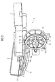
- Fig. 2 further shows that in the infeed area 3 on the outer side of the rail construction 9 an incline 15 is provided around the outer side of the container 2 to raise opposite the inside.
- the containers 2 fed to the infeed area 3 can separate are in a queue. You will then use a pawl 16 brought into the takeover position in which it be releasably connected to one of the carriages 8. In this The upper part of the carriage 8 is in the position Recess 14 in the bottom of the container 2, approximately in the middle of the Container long side.
- a driven one Vertical belt to support the jacking device 5 be used, which with the same speed and in same direction as the conveyor belt 6 is moved.
- the Container jacking device can both by means of friction as well as by means of positive locking (not shown) become.
- FIG. 3 shows an alternative embodiment for lifting the outer side of the container 2.
- two rails 17, an outer rail 17a and an inner rail 17b are provided as sliding rails on the outside along the conveyor track curve
- Container support surfaces 18 lie above the conveyor belt 6.
- the rails 17 point in the entrance area of the conveyor track curve ramps 19 offset in the direction of movement of the containers 2, the ramp 19b of the inner rail 17b in front of the outer ramp 19a begins.
- the container is conveyed in by means of two Conveyor belts 20, on which the container 2 lying on the Conveyor belt 6 are taken over.
- To guide the container 2 serves a guide profile 21st
- FIG. 4 shows the feed area according to FIG. 3 from a another direction for better understanding upright container 2. You look directly at Fig. 4 the bottom of the container, where recesses 22, 23, 24 and Surfaces 25, 26 are arranged. The recesses 22, 23 and the surfaces 25, 26 are designed such that the container 2 is evenly raised on the outside, i.e. the outer edge 27 of the container 2 runs in each case horizontal.
Landscapes
- Engineering & Computer Science (AREA)
- Mechanical Engineering (AREA)
- Aviation & Aerospace Engineering (AREA)
- Intermediate Stations On Conveyors (AREA)
- Warehouses Or Storage Devices (AREA)
Applications Claiming Priority (4)
| Application Number | Priority Date | Filing Date | Title |
|---|---|---|---|
| DE10308657 | 2003-02-27 | ||
| DE10308657 | 2003-02-27 | ||
| DE10315404 | 2003-04-04 | ||
| DE10315404A DE10315404B4 (de) | 2003-02-27 | 2003-04-04 | Fördersystem für Behälter, insbesondere eine Flughafen-Gepäckförderanlage |
Publications (1)
| Publication Number | Publication Date |
|---|---|
| EP1452465A1 true EP1452465A1 (fr) | 2004-09-01 |
Family
ID=32773169
Family Applications (1)
| Application Number | Title | Priority Date | Filing Date |
|---|---|---|---|
| EP04090063A Withdrawn EP1452465A1 (fr) | 2003-02-27 | 2004-02-23 | Système de transport pour conteneurs, en particulier pour un système de convoyeur de bagages dans un aéroport |
Country Status (2)
| Country | Link |
|---|---|
| US (1) | US7025195B2 (fr) |
| EP (1) | EP1452465A1 (fr) |
Cited By (1)
| Publication number | Priority date | Publication date | Assignee | Title |
|---|---|---|---|---|
| CN116113588A (zh) * | 2020-08-28 | 2023-05-12 | 株式会社大福 | 托盘和输送设备 |
Families Citing this family (6)
| Publication number | Priority date | Publication date | Assignee | Title |
|---|---|---|---|---|
| US7954627B2 (en) * | 2007-03-23 | 2011-06-07 | Btsystems, Llc | Bin transporter system |
| US7870950B2 (en) * | 2007-06-28 | 2011-01-18 | Rinne Rhett L | V-shaped product conveyor |
| WO2009111594A2 (fr) * | 2008-03-04 | 2009-09-11 | Ingram Micro Inc. | Système et procédé d'alignement d'articles sur un transporteur |
| WO2018160918A1 (fr) | 2017-03-02 | 2018-09-07 | Walmart Apollo, Llc | Systèmes et procédés de réception d'expédition comprenant des caractéristiques de notification et de réconciliation |
| CA3055196C (fr) * | 2017-03-02 | 2020-05-26 | Walmart Apollo, Llc | Systeme de transport qui detecte et separe un produit |
| US10934099B2 (en) * | 2018-05-02 | 2021-03-02 | Caromation, Inc. | Electric pallet conveyor |
Citations (2)
| Publication number | Priority date | Publication date | Assignee | Title |
|---|---|---|---|---|
| EP1094018A1 (fr) * | 1999-10-18 | 2001-04-25 | Ebm Techniek B.V. | Ensemble de transport |
| DE20213326U1 (de) * | 2002-08-30 | 2003-02-20 | Dennerlein GmbH, 28307 Bremen | Transportvorrichtung für Stückgüter |
Family Cites Families (13)
| Publication number | Priority date | Publication date | Assignee | Title |
|---|---|---|---|---|
| US3507379A (en) * | 1968-03-28 | 1970-04-21 | Associated Millwrights Inc | Power curve |
| US4043445A (en) * | 1975-02-10 | 1977-08-23 | S.I. Handling Systems Inc. | Centrifugal rotary transfer apparatus |
| DE4035128A1 (de) | 1990-11-05 | 1992-06-17 | Ernst Dipl Ing Hoermann | Kurvenneigbares, mehrspuriges fahrzeug |
| DK167274B1 (da) | 1991-06-18 | 1993-10-04 | Cosan Crisplant As | Fremgangsmaade til destinationssortering og lejlighedsvis mellemlagring af stykgods, f.eks. flybagage, samt sorterings- og lagringsanlaeg til udoevelse af fremgangsmaaden og baerebakke til brug i dette anlaeg |
| DE4141426A1 (de) | 1991-12-16 | 1993-06-17 | Armin Mylaeus | Rohrschnellbahn und pipeline |
| DE4210387C2 (de) | 1992-03-30 | 1994-03-24 | Denki Kagaku Kogyo Kk | Verfahren und Vorrichtung zur kontinuierlichen Beförderung und Behandlung von hochtemperaturgeschmolzenem Material |
| NL9302211A (nl) | 1993-12-20 | 1995-07-17 | Vanderlande Ind Nederland | Transportinstallatie. |
| US5544733A (en) * | 1994-09-30 | 1996-08-13 | Jervis B. Webb Company | Wheeled luggage tipper |
| DE19511912A1 (de) | 1995-03-31 | 1996-10-02 | Fam Magdeburger Foerderanlagen | Gurtführungsstation |
| DE19721726C1 (de) | 1997-05-24 | 1998-07-30 | Logotech Gmbh | Hängefördersystem |
| US6273241B1 (en) * | 1999-03-18 | 2001-08-14 | United Parcel Service Of America, Inc. | Powered conveyor turn having improved repair features |
| DE10116882A1 (de) | 2001-04-04 | 2002-10-17 | Bombardier Transp Gmbh | Verfahren zur Steuerung des Neigungswinkels eines Wagenkastens gegenüber einem Fahrwerk eines Fahrzeugs und Fahrzeug zur Ausübung des Verfahrens |
| US6601697B2 (en) * | 2001-07-25 | 2003-08-05 | Hartness International | Sloped surface conveyor belt |
-
2004
- 2004-02-23 EP EP04090063A patent/EP1452465A1/fr not_active Withdrawn
- 2004-02-27 US US10/789,196 patent/US7025195B2/en not_active Expired - Fee Related
Patent Citations (2)
| Publication number | Priority date | Publication date | Assignee | Title |
|---|---|---|---|---|
| EP1094018A1 (fr) * | 1999-10-18 | 2001-04-25 | Ebm Techniek B.V. | Ensemble de transport |
| DE20213326U1 (de) * | 2002-08-30 | 2003-02-20 | Dennerlein GmbH, 28307 Bremen | Transportvorrichtung für Stückgüter |
Cited By (3)
| Publication number | Priority date | Publication date | Assignee | Title |
|---|---|---|---|---|
| CN116113588A (zh) * | 2020-08-28 | 2023-05-12 | 株式会社大福 | 托盘和输送设备 |
| EP4194381A4 (fr) * | 2020-08-28 | 2024-06-26 | Daifuku Co., Ltd. | Plateau et installation de transport |
| US12391486B2 (en) | 2020-08-28 | 2025-08-19 | Daifuku Co., Ltd. | Tray and transport facility |
Also Published As
| Publication number | Publication date |
|---|---|
| US7025195B2 (en) | 2006-04-11 |
| US20040168893A1 (en) | 2004-09-02 |
Similar Documents
| Publication | Publication Date | Title |
|---|---|---|
| DE102007017511C5 (de) | Antriebseinheit, Antriebssystem und Förderanlage für Skids zum Tragen eines Gegenstandes | |
| DE3104740A1 (de) | Foerder- und/oder sortiereinrichtung, zugeordneter wagen bzw. schlitten und diese einrichtung und derartige wagen bzw. schlitten enthaltende anlage | |
| DE69903284T2 (de) | Verfahren und einrichtung zum transport von gütern, sowie kombination von behältern und gestell mit stützrädern | |
| EP0230919A2 (fr) | Convoyeur à plateaux basculants pour des objets | |
| DE10121053A1 (de) | Fördervorrichtung zum Fördern von Werkstücken durch einen Behandlungsbereich zur Oberflächenbehandlung der Werkstücke | |
| EP0059984B1 (fr) | Dispositif de distribution pour un convoyeur | |
| EP0067421A2 (fr) | Système de transport à surface porteuse | |
| DE3612128A1 (de) | Vorrichtung zum transportieren von kraftfahrzeug-karosserien laengs einer mit elektrophorese arbeitenden phosphatierungs- und lackierungsanlage | |
| DE102015003758B4 (de) | Verfahren und Vorrichtung zur Übergabe eines Transportgutes von einem Längsförderer auf einen schienengebundenen Transportroboter | |
| DE4225491C1 (de) | Vorrichtung zum Entleeren von Behältern | |
| EP1452465A1 (fr) | Système de transport pour conteneurs, en particulier pour un système de convoyeur de bagages dans un aéroport | |
| DE2537442C2 (de) | Umladevorrichtung an Hängebahnen | |
| DE10315404B4 (de) | Fördersystem für Behälter, insbesondere eine Flughafen-Gepäckförderanlage | |
| EP0737631B1 (fr) | Dispositif de distribution d'objets | |
| DE3917630A1 (de) | Vorrichtung zum haengenden transport von gegenstaenden, insbesondere kleidungsstuecken, durch eine behandlungseinrichtung | |
| EP1512645B1 (fr) | Système de transport, en particulier pour baggage dans des aéroports | |
| DE1989386U (de) | Foerdervorrichtung fuer kundenwagen. | |
| DE4032772C1 (en) | Loader-unloader for containers or wagons - incorporates intermediate- and curved segment conveyors | |
| EP0852560A1 (fr) | Dispositif pour transporter une couche de recipients en verre sur une palette | |
| DE4211682A1 (de) | Verfahren und Vorrichtung zur Beschickung und Entleerung eines Stapelgleises | |
| EP0407643A1 (fr) | Appareil pour le chargement et déchargement, en particulier de navires avec une charge isolée et/ou des palettes chargées | |
| EP0899221A1 (fr) | Transporteur à palettes pour transporter des articles, en particulier des pièces de baggage | |
| DE2137770A1 (de) | Teigstueckbearbeitungseinrichtung | |
| EP0577937B1 (fr) | Dispositif pour distribuer et entreposer des biens | |
| DE2110979C3 (de) | Stückgutkreisförderer mit mehreren Aufgabestellen |
Legal Events
| Date | Code | Title | Description |
|---|---|---|---|
| PUAI | Public reference made under article 153(3) epc to a published international application that has entered the european phase |
Free format text: ORIGINAL CODE: 0009012 |
|
| AK | Designated contracting states |
Kind code of ref document: A1 Designated state(s): AT BE BG CH CY CZ DE DK EE ES FI FR GB GR HU IE IT LI LU MC NL PT RO SE SI SK TR |
|
| AX | Request for extension of the european patent |
Extension state: AL HR LT LV MK |
|
| 17P | Request for examination filed |
Effective date: 20050120 |
|
| AKX | Designation fees paid |
Designated state(s): DE DK FR GB IT NL |
|
| RBV | Designated contracting states (corrected) |
Designated state(s): DE DK FR GB IT NL |
|
| 17Q | First examination report despatched |
Effective date: 20070216 |
|
| STAA | Information on the status of an ep patent application or granted ep patent |
Free format text: STATUS: THE APPLICATION IS DEEMED TO BE WITHDRAWN |
|
| 18D | Application deemed to be withdrawn |
Effective date: 20070627 |