EP1452654A2 - Verfahren zur Durchführung einer Flüssigkeitsströmung in porösen Materialien - Google Patents
Verfahren zur Durchführung einer Flüssigkeitsströmung in porösen Materialien Download PDFInfo
- Publication number
- EP1452654A2 EP1452654A2 EP04008960A EP04008960A EP1452654A2 EP 1452654 A2 EP1452654 A2 EP 1452654A2 EP 04008960 A EP04008960 A EP 04008960A EP 04008960 A EP04008960 A EP 04008960A EP 1452654 A2 EP1452654 A2 EP 1452654A2
- Authority
- EP
- European Patent Office
- Prior art keywords
- electrodes
- water
- voltage
- pulse
- potential difference
- Prior art date
- Legal status (The legal status is an assumption and is not a legal conclusion. Google has not performed a legal analysis and makes no representation as to the accuracy of the status listed.)
- Withdrawn
Links
- 238000000034 method Methods 0.000 title claims abstract description 58
- 239000012530 fluid Substances 0.000 title claims abstract description 20
- 239000011148 porous material Substances 0.000 title description 23
- 230000000694 effects Effects 0.000 claims abstract description 12
- XLYOFNOQVPJJNP-UHFFFAOYSA-N water Substances O XLYOFNOQVPJJNP-UHFFFAOYSA-N 0.000 claims description 32
- 230000002262 irrigation Effects 0.000 claims description 5
- 238000003973 irrigation Methods 0.000 claims description 5
- 238000006073 displacement reaction Methods 0.000 claims description 2
- 239000002184 metal Substances 0.000 description 31
- 239000004567 concrete Substances 0.000 description 27
- 230000002787 reinforcement Effects 0.000 description 22
- 230000008569 process Effects 0.000 description 11
- 239000011150 reinforced concrete Substances 0.000 description 9
- 230000007797 corrosion Effects 0.000 description 7
- 238000005260 corrosion Methods 0.000 description 7
- 238000005370 electroosmosis Methods 0.000 description 7
- 230000001276 controlling effect Effects 0.000 description 6
- 238000001208 nuclear magnetic resonance pulse sequence Methods 0.000 description 6
- 229910000831 Steel Inorganic materials 0.000 description 5
- 239000004566 building material Substances 0.000 description 5
- 230000003014 reinforcing effect Effects 0.000 description 5
- 239000010959 steel Substances 0.000 description 5
- 230000008901 benefit Effects 0.000 description 4
- 230000015572 biosynthetic process Effects 0.000 description 4
- 230000005012 migration Effects 0.000 description 4
- 238000013508 migration Methods 0.000 description 4
- 230000005684 electric field Effects 0.000 description 3
- 239000007789 gas Substances 0.000 description 3
- 239000003673 groundwater Substances 0.000 description 3
- 239000012535 impurity Substances 0.000 description 3
- 239000000463 material Substances 0.000 description 3
- 230000003204 osmotic effect Effects 0.000 description 3
- 230000009467 reduction Effects 0.000 description 3
- 230000004044 response Effects 0.000 description 3
- 239000004568 cement Substances 0.000 description 2
- 239000004927 clay Substances 0.000 description 2
- 238000010586 diagram Methods 0.000 description 2
- 238000000605 extraction Methods 0.000 description 2
- 229910052500 inorganic mineral Inorganic materials 0.000 description 2
- 239000007788 liquid Substances 0.000 description 2
- 239000011159 matrix material Substances 0.000 description 2
- 239000011707 mineral Substances 0.000 description 2
- 230000004048 modification Effects 0.000 description 2
- 238000012986 modification Methods 0.000 description 2
- 230000035515 penetration Effects 0.000 description 2
- 239000000523 sample Substances 0.000 description 2
- 238000009416 shuttering Methods 0.000 description 2
- 238000012546 transfer Methods 0.000 description 2
- OKTJSMMVPCPJKN-UHFFFAOYSA-N Carbon Chemical compound [C] OKTJSMMVPCPJKN-UHFFFAOYSA-N 0.000 description 1
- VEXZGXHMUGYJMC-UHFFFAOYSA-M Chloride anion Chemical compound [Cl-] VEXZGXHMUGYJMC-UHFFFAOYSA-M 0.000 description 1
- 229920002943 EPDM rubber Polymers 0.000 description 1
- UFHFLCQGNIYNRP-UHFFFAOYSA-N Hydrogen Chemical compound [H][H] UFHFLCQGNIYNRP-UHFFFAOYSA-N 0.000 description 1
- 230000002411 adverse Effects 0.000 description 1
- 230000004075 alteration Effects 0.000 description 1
- 229910052799 carbon Inorganic materials 0.000 description 1
- 150000001805 chlorine compounds Chemical class 0.000 description 1
- 150000001875 compounds Chemical class 0.000 description 1
- 230000006835 compression Effects 0.000 description 1
- 238000007906 compression Methods 0.000 description 1
- 239000000470 constituent Substances 0.000 description 1
- 238000010276 construction Methods 0.000 description 1
- 238000013461 design Methods 0.000 description 1
- 230000006866 deterioration Effects 0.000 description 1
- 230000009977 dual effect Effects 0.000 description 1
- 230000002349 favourable effect Effects 0.000 description 1
- 239000010439 graphite Substances 0.000 description 1
- 229910002804 graphite Inorganic materials 0.000 description 1
- 239000007770 graphite material Substances 0.000 description 1
- 229910052739 hydrogen Inorganic materials 0.000 description 1
- 239000001257 hydrogen Substances 0.000 description 1
- -1 hydrogen ions Chemical class 0.000 description 1
- 150000002500 ions Chemical class 0.000 description 1
- 239000000203 mixture Substances 0.000 description 1
- 230000007935 neutral effect Effects 0.000 description 1
- 239000003129 oil well Substances 0.000 description 1
- 230000001105 regulatory effect Effects 0.000 description 1
- 230000008439 repair process Effects 0.000 description 1
- 230000003019 stabilising effect Effects 0.000 description 1
Images




Classifications
-
- B—PERFORMING OPERATIONS; TRANSPORTING
- B09—DISPOSAL OF SOLID WASTE; RECLAMATION OF CONTAMINATED SOIL
- B09C—RECLAMATION OF CONTAMINATED SOIL
- B09C1/00—Reclamation of contaminated soil
- B09C1/08—Reclamation of contaminated soil chemically
- B09C1/085—Reclamation of contaminated soil chemically electrochemically, e.g. by electrokinetics
-
- A—HUMAN NECESSITIES
- A01—AGRICULTURE; FORESTRY; ANIMAL HUSBANDRY; HUNTING; TRAPPING; FISHING
- A01G—HORTICULTURE; CULTIVATION OF VEGETABLES, FLOWERS, RICE, FRUIT, VINES, HOPS OR SEAWEED; FORESTRY; WATERING
- A01G25/00—Watering gardens, fields, sports grounds or the like
-
- A—HUMAN NECESSITIES
- A01—AGRICULTURE; FORESTRY; ANIMAL HUSBANDRY; HUNTING; TRAPPING; FISHING
- A01G—HORTICULTURE; CULTIVATION OF VEGETABLES, FLOWERS, RICE, FRUIT, VINES, HOPS OR SEAWEED; FORESTRY; WATERING
- A01G7/00—Botany in general
- A01G7/04—Electric or magnetic or acoustic treatment of plants for promoting growth
-
- B—PERFORMING OPERATIONS; TRANSPORTING
- B01—PHYSICAL OR CHEMICAL PROCESSES OR APPARATUS IN GENERAL
- B01D—SEPARATION
- B01D61/00—Processes of separation using semi-permeable membranes, e.g. dialysis, osmosis or ultrafiltration; Apparatus, accessories or auxiliary operations specially adapted therefor
- B01D61/42—Electrodialysis; Electro-osmosis ; Electro-ultrafiltration; Membrane capacitive deionization
- B01D61/56—Electro-osmotic dewatering
-
- C—CHEMISTRY; METALLURGY
- C02—TREATMENT OF WATER, WASTE WATER, SEWAGE, OR SLUDGE
- C02F—TREATMENT OF WATER, WASTE WATER, SEWAGE, OR SLUDGE
- C02F1/00—Treatment of water, waste water, or sewage
- C02F1/46—Treatment of water, waste water, or sewage by electrochemical methods
- C02F1/469—Treatment of water, waste water, or sewage by electrochemical methods by electrochemical separation, e.g. by electro-osmosis, electrodialysis, electrophoresis
- C02F1/4698—Treatment of water, waste water, or sewage by electrochemical methods by electrochemical separation, e.g. by electro-osmosis, electrodialysis, electrophoresis electro-osmosis
-
- E—FIXED CONSTRUCTIONS
- E02—HYDRAULIC ENGINEERING; FOUNDATIONS; SOIL SHIFTING
- E02D—FOUNDATIONS; EXCAVATIONS; EMBANKMENTS; UNDERGROUND OR UNDERWATER STRUCTURES
- E02D1/00—Investigation of foundation soil in situ
- E02D1/02—Investigation of foundation soil in situ before construction work
- E02D1/027—Investigation of foundation soil in situ before construction work by investigating properties relating to fluids in the soil, e.g. pore-water pressure, permeability
-
- E—FIXED CONSTRUCTIONS
- E02—HYDRAULIC ENGINEERING; FOUNDATIONS; SOIL SHIFTING
- E02D—FOUNDATIONS; EXCAVATIONS; EMBANKMENTS; UNDERGROUND OR UNDERWATER STRUCTURES
- E02D3/00—Improving or preserving soil or rock, e.g. preserving permafrost soil
- E02D3/02—Improving by compacting
- E02D3/10—Improving by compacting by watering, draining, de-aerating or blasting, e.g. by installing sand or wick drains
-
- E—FIXED CONSTRUCTIONS
- E02—HYDRAULIC ENGINEERING; FOUNDATIONS; SOIL SHIFTING
- E02D—FOUNDATIONS; EXCAVATIONS; EMBANKMENTS; UNDERGROUND OR UNDERWATER STRUCTURES
- E02D3/00—Improving or preserving soil or rock, e.g. preserving permafrost soil
- E02D3/11—Improving or preserving soil or rock, e.g. preserving permafrost soil by thermal, electrical or electro-chemical means
-
- E—FIXED CONSTRUCTIONS
- E03—WATER SUPPLY; SEWERAGE
- E03B—INSTALLATIONS OR METHODS FOR OBTAINING, COLLECTING, OR DISTRIBUTING WATER
- E03B3/00—Methods or installations for obtaining or collecting drinking water or tap water
- E03B3/06—Methods or installations for obtaining or collecting drinking water or tap water from underground
-
- E—FIXED CONSTRUCTIONS
- E04—BUILDING
- E04B—GENERAL BUILDING CONSTRUCTIONS; WALLS, e.g. PARTITIONS; ROOFS; FLOORS; CEILINGS; INSULATION OR OTHER PROTECTION OF BUILDINGS
- E04B1/00—Constructions in general; Structures which are not restricted either to walls, e.g. partitions, or floors or ceilings or roofs
- E04B1/62—Insulation or other protection; Elements or use of specified material therefor
- E04B1/70—Drying or keeping dry, e.g. by air vents
- E04B1/7007—Drying or keeping dry, e.g. by air vents by using electricity, e.g. electro-osmosis
-
- E—FIXED CONSTRUCTIONS
- E21—EARTH OR ROCK DRILLING; MINING
- E21B—EARTH OR ROCK DRILLING; OBTAINING OIL, GAS, WATER, SOLUBLE OR MELTABLE MATERIALS OR A SLURRY OF MINERALS FROM WELLS
- E21B43/00—Methods or apparatus for obtaining oil, gas, water, soluble or meltable materials or a slurry of minerals from wells
- E21B43/16—Enhanced recovery methods for obtaining hydrocarbons
- E21B43/24—Enhanced recovery methods for obtaining hydrocarbons using heat, e.g. steam injection
- E21B43/2401—Enhanced recovery methods for obtaining hydrocarbons using heat, e.g. steam injection by means of electricity
Definitions
- the present invention relates to a method of effecting fluid flow in porous materials and relates particularly, to a method of effecting fluid flow by means of electroosmosis.
- Metal reinforced concrete has widespread uses in the construction industry, for example as walls, floors, columns of a building, bridge spans or piers, and many other such applications.
- Steel reinforcing rods are usually employed to provide metal reinforcement of cast concrete structures, so as to provide a matrix on which the cast material can be formed. This increases the resistance to tensile stresses of the cast building element, since concrete is strong in compression but much weaker in tension.
- the cast building elements are usually constructed by locating metal reinforcing rods at desired locations within the intended cast structure, between shuttering, and then pouring the cast material into a space defined by the shuttering so as to surround the metal reinforcing rods. On setting of the cast material, the metal reinforcements become rigidly embedded within the cast slabs.
- metal reinforced concrete Although the metal reinforcements usually remain firmly embedded within the cast structure, problems often arise with metal reinforced concrete as a result of water penetration to the metal reinforcement. Such water penetration is a source of corrosion of metal reinforcements over a period of time, and the constituents of the concrete mixture may also have an adverse effect on the metal reinforcement. This can result in failure of the cast structure which in the case of building elements, can have very serious consequences.
- Electroosmosis involves subjecting such a porous body to an electric field, which causes part of the double layer to tend to migrate under the influence of the field, which in turn can cause some of the free liquid in the pulses to be carried along in this process. This can lead to a significant reduction in the internal moisture content of the porous body.
- US patent 5015351 proposes the removal of water from porous building materials by applying a controlled cyclical voltage to an electrode system to effect osmotic migration of water from an anode located within the structure to a cathode spaced from the structure but in electrical contact therewith.
- the cycle includes a first energy pulse in a direction to effect osmotic migration, followed by a shorter pulse of reverse polarity to counteract formation of insulating gas films.
- the process proposed in US patent 5015351 is believed to give unsatisfactory results when used on metal reinforced concrete structures.
- a fixed pulse system does not have the ability to deal with variations in the design of reinforced concrete structures.
- Preferred embodiments of the present invention seek to overcome the above disadvantages of the prior art.
- the method comprising applying a sequence of voltage pulses between spaced apart first and second electrodes having a region of the porous material therebetween, each said voltage pulse comprising a first portion in which an electroosmotically active first potential difference is applied between said first and second electrodes to effect fluid movement in said region of porous material, and a second portion in which a second potential difference of opposite polarity to said first potential difference is applied between said first and second electrodes; and applying a voltage to a metal reinforcement located at least partly in said region of porous material to make the voltage of said metal reinforcement negative with respect to the porous material adjacent thereto for at least part of said sequence of voltage pulses.
- each pulse enables fluid movement in the porous material to be effected, while the provision of the second portion at least partly counteracts the formation of gas or other insulating films at the electrodes (which leads to a deterioration in the electrical performance of the system and results in low operating efficiency) and / or the formation of corrosion products.
- Making the voltage of the metal reinforcement negative with respect to the porous material adjacent thereto provides the further advantage of preventing or minimising corrosion of the metal reinforcement which may otherwise occur as a result of the electroosmosis process.
- the method is a method of controlling humidity in a metal reinforced building material, and wherein said first potential difference is positive.
- the process can be used to effect electroosmotic reduction in the humidity internal to a metal reinforced building material. This helps to reduce the corrosive nature of the surroundings of the metal reinforcement, whilst minimising corrosion of the metal reinforcement as a result of the electroosmosis process.
- the building material is concrete.
- the method may be a method of treating water in which said porous material is immersed, and in which said first potential difference is negative to effect electroosmotic movement of humidity through said porous material.
- the porous material acts as a filter to remove impurities from the water.
- the method is a method of raising the pH level in said water.
- Each said pulse may comprise a third portion following said second portions and in which a third potential difference having an amplitude between that of said first and second portions is applied between said electrodes.
- each said third portion may be substantially zero.
- said first and / or second portions have substantially rectangular waveforms.
- the first potential difference may vary from substantially +40V to substantially -40V.
- said first potential difference is substantially 80V and the voltage applied to each said electrode differs by substantially 40V from earth potential.
- the second potential difference may be substantially - 40V.
- the voltage applied to the metal reinforcement is applied in the form of a series of pulses.
- Said voltage pulses are advantageously applied to said metal reinforcement during said first portion only of each pulse.
- each said voltage pulse has an on portion and an off portion of substantially equal duration to the on portion.
- each said voltage pulse has an on portion having a duration of from substantially 0.001 seconds to substantially 1.0 seconds.
- each said third portion may be from 0 to substantially 200% of said first portion.
- the duration of the third portion may be from substantially 1% to substantially 200% of the duration of a said first portion.
- each said second portion may be from 0 to substantially 90% of the duration of said first portion.
- each said second portion is preferably from substantially 1% to substantially 90% of the duration of said first portion.
- the method advantageously further comprises the step of automatically controlling the duration and / or amplitude of said portions in response to detected fluid conditions in the porous material.
- a method of effecting fluid movement in porous geological media comprising applying a sequence of voltage pulses between spaced apart first and second electrodes having a region of porous geological medium therebetween, each said voltage pulse comprising a first portion in which an electroosmotically active first potential difference is applied between said first and second electrodes to effect fluid movement in said region of porous geological medium, and a second portion in which a second potential difference of opposite polarity to said first potential difference is applied between said first and second electrodes.
- the geological medium may be ground and the fluid may be water.
- the method is a method of irrigation.
- the method may be a method of water removal.
- the geological medium comprises oil bearing strata and the fluid is water, wherein the method is a method of oil displacement as a result of water movement in the oil bearing strata.
- the method may be a method of controlling pollution in the ground.
- the method further comprises the step of applying sequentially increasing voltages to said first electrode at respective locations of increasing depth in the geological medium.
- said voltage pulses are applied to a plurality of said first electrodes.
- Said voltage pulses may have a maximum amplitude of substantially 10,000v to substantially 100,000v.
- a metal reinforced concrete building element 1 has a reinforcing metal structure 2 embedded in concrete 3.
- a series of positive first electrodes 4 are embedded in one face of the concrete structure 1, and have spacing determined by the parameters of the particular process, but spacing would be typically of the order of 5 to 10 metres between electrodes 4.
- a negative electrode 5 is embedded in the opposite face of the concrete structure 1, so that a potential difference applied to the electrodes 4, 5 causes an electric field to act across region 6 of the concrete 3 between the electrodes 4, 5 such that the region 6 at least partly encloses the metal reinforcing structure 2.
- a positive electrode 7 is connected to the steel reinforcement 2 and a positive voltage having lower amplitude than that applied to electrodes 4 is applied to electrode 7.
- the electrodes 4, 7 may be surrounded by graphite material to enhance the electrical conductivity thereof.
- a series of pulses (A) is applied to electrodes 4.
- Each pulse (A) has a duration of the order of substantially 0.1ms to substantially 10s and comprises a first portion 8 of amplitude of the order of 40 volts and duration 0.1ms to 10s, a second portion 9 of amplitude of the order of -40 volts and duration 0.1ms to 10s, and a third portion 10 of amplitude approximately equal to earth potential and duration 0.1s to 10s.
- a constant negative voltage (B) of amplitude of the order of -40V is applied to electrode 5.
- first portion 8 therefore, a large positive potential difference exists between electrodes 4 and 5, which creates an electroosmotically active electric field across region 6 which causes electroosmotic fluid flow in the concrete 3 such that negative ions (including chloride ions) move towards positive electrodes 4 and hydrogen ions are attracted towards negative electrode 5.
- the first portion 8 of each pulse causes the humidity within the concrete 3 to be reduced to a level of the order of 60% to 70%, and the level of chlorides, which contribute to corrosion of the metal reinforcement 2, to be reduced, for example by up to 92% by weight of cement.
- the ph values in the concrete 3 also generally increase, typically up to a value of 12.5, but without generating potentially harmful pH levels as. a result of the first portion 8 of pulses (A).
- a series of chopped negative voltage pulses (C) is applied to the metal reinforcement 2 during the first portion 8 of pulses (A). This makes the electric potential of the metal reinforcement 2 negative with respect to the adjacent region 6 of concrete, which reduces the tendency of the metal reinforcement 2 to corrode, which would otherwise be exacerbated during the first portion 8 of the pulses (A).
- table 1 below sets out a range of six pulse regimes A to F, in which the first to third columns respectively show the first 8, second 9, and third 10 portions of the pulse pattern applied between the electrodes 4, 5, and the fourth column represents the duration of the on portion of the chopped negative pulses applied to the metal reinforcement 2.
- the off portion of each pulse is generally equal in duration to the on portion.
- electrode 5 becomes covered in a film of hydrogen gas, which impairs the electrical characteristics of the system and results in lower operating efficiency.
- the formation of gas or other insulating films of the electrodes 4, 5 is either prevented or reduced to an acceptable level.
- the energy transfer of the first portion 8 is greater than that of the second portion 9, there is a net osmotic energy transfer, which causes a net reduction in the humidity of region 6 of the concrete 3.
- the third portion 10 has advantageous effects in re-setting the conditions within the concrete 3 before arrival of the first portion 8 of the next pulse (A).
- positive electrodes 4, 7 are surrounded by a graphite enriched cement, whilst the negative electrode 5 is covered with a highly cementitious repair compound. While the spacing between the positive electrodes 4 may be 5 to 10 metres, it has been found that a particularly advantageous spacing in the context of building materials is 8 metres, whereas the spacing in prior art systems would typically be of the order of 30cm. This therefore has advantageous effects in reducing the number of electrodes 4 that are necessary.
- the amount of power used by the system will be a maximum when the system is first started (i.e. when the humidity within region 6 of the concrete 3 is high).
- the parameters of the pulse wave forms (A) and (C) can be adjusted. Accordingly, the humidity conditions within the concrete 3 can be monitored by means of suitable probes or sensors (not shown) which in turn can be connected via a suitable control means such as a micro processor to a pulse generator (not shown) for producing wave forms (A), (B) and (C).
- Table 2 shows the pulse patterns of Table 1 which provide the most favourable results over a predetermined range of relative humidity in concrete of various qualities.
- the polarity of the voltages applied to electrodes 4, 5 can be reversed with respect to the arrangements shown in Figures 1 to 3 in a sacrificial reinforced concrete block which is immersed in water.
- Application of the pulses (A) to (C) then causes humidity to move through the concrete block by means of electroosmosis, as a result of which the concrete block acts as a filter and removes impurities from the water, and also raises the pH level in the water surrounding the concrete block.
- the method of removing impurities from water and / or raising the pH level of water as described above can be applied to the control of pollution of bodies of water, for example lakes.
- the negative electrode is placed as close as possible to the body of the concrete block, which typically has a quality of C25 to C45, and voltage pulses of amplitude 40V to 10,000V are typically applied.
- the process can be regulated in response to a pH probe placed some distance from the concrete block, and it is also envisaged that a power supply could be derived from solar panels. This would enable the process to be used in locations distant from electrical mains supply.
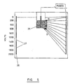
- an irrigation system 20 comprises a well 21 provided in the ground 22, and an elongate negative electrode 5 is arranged vertically in the well 21.
- a series of vertically arranged elongate positive electrodes 4 are arranged at generally equi-angularly spaced intervals around the circumference of a circle at the centre of which the negative electrode 5 is arranged, and neighbouring positive electrodes 4 are connected to each other by means of EPDM cables 23.
- the spacing between neighbouring positive electrodes 4 will depend upon a number of factors, including the electrical resistance of the ground and its capillary pore size.
- Each of the positive electrodes 4 consists of an elongate rod forming an active electrode such that voltages of increasing amplitude with depth below the ground surface can be applied to the electrodes 4.
- each positive electrode 4 comprises an elongate rod 26 having adjacent voltage application regions 27 such that voltages with amplitude increasing with depth below the ground surface can be applied to the electrodes 4.
- the amplitude of the voltage pulse will be of the order of 40 v to 100,000 v.
- an under sea oil well system comprises a well head 30, pipe work 31 connected thereto, and a collection region 32 at the end of the pipe work 31 remote from the well head 30.
- a series of positive electrodes 4 in the form of elongate rods 26 similar to those shown in Figures 4 to 6 are arranged at spaced apart locations passing from the sea bed 33 through mineral strata 34 to oil bearing strata 35.
- a negative electrode 5 in the form of a similar elongate rod passes from the sea bed through mineral strata 24 into the oil bearing strata 35 such that the collection point 31 is arranged at the lower end of electrode 5.
- Oil is a non-conductive liquid, and cannot therefore be directly moved by means of an electroosmotic system as described above.
- natural ground water in the oil bearing strata can be moved by means of a voltage pulse sequence of shape similar to those shown in Figure 2 applied between positive electrodes 4 and negative electrode 5.
- Such movement of the ground water effects movement of oil trapped within the pore structure of the oil bearing strata 35 with the result that oil migrates towards the collection region 32 as shown by arrows E, and such collection in a single region therefore facilitates extraction of the oil to the well head 30.
- Figure 7b shows a similar system to that of Figure 7a, but in which the oil extraction system is not located at the sea bottom.
- Figure 8 shows how the length of the first, second and third portions of the pulses applied between the positive 4 and negative 5 electrodes varies in length depending upon the size of the pore structure of the porous material in which fluid movement is to be effected. It can therefore be seen that higher pulse frequencies are appropriate for smaller pore sizes.
- the system of the embodiments of the present invention can therefore be controlled by any suitable means, such as a microprocessor in order to maintain the optimum pulse shape and / or frequency.
Landscapes
- Engineering & Computer Science (AREA)
- Life Sciences & Earth Sciences (AREA)
- Chemical & Material Sciences (AREA)
- Structural Engineering (AREA)
- Water Supply & Treatment (AREA)
- Environmental & Geological Engineering (AREA)
- Mining & Mineral Resources (AREA)
- Chemical Kinetics & Catalysis (AREA)
- Soil Sciences (AREA)
- Civil Engineering (AREA)
- General Life Sciences & Earth Sciences (AREA)
- Health & Medical Sciences (AREA)
- Hydrology & Water Resources (AREA)
- General Engineering & Computer Science (AREA)
- Paleontology (AREA)
- Environmental Sciences (AREA)
- Physics & Mathematics (AREA)
- Architecture (AREA)
- Electrochemistry (AREA)
- Agronomy & Crop Science (AREA)
- Geology (AREA)
- Analytical Chemistry (AREA)
- Electromagnetism (AREA)
- Ecology (AREA)
- Public Health (AREA)
- Molecular Biology (AREA)
- Organic Chemistry (AREA)
- Biodiversity & Conservation Biology (AREA)
- Botany (AREA)
- Urology & Nephrology (AREA)
- Forests & Forestry (AREA)
- Fluid Mechanics (AREA)
- General Chemical & Material Sciences (AREA)
- Geochemistry & Mineralogy (AREA)
- Water Treatment By Electricity Or Magnetism (AREA)
- Fluidized-Bed Combustion And Resonant Combustion (AREA)
Applications Claiming Priority (5)
| Application Number | Priority Date | Filing Date | Title |
|---|---|---|---|
| GBGB9513080.3A GB9513080D0 (en) | 1995-06-27 | 1995-06-27 | Cathodic protection of metal reinforcement in cast building elements |
| GB9513080 | 1995-06-27 | ||
| GB9520379A GB2302696B (en) | 1995-06-27 | 1995-10-05 | Method of effecting fluid flow in porous materials |
| GB9520379 | 1995-10-05 | ||
| EP96920975A EP0847464B1 (de) | 1995-06-27 | 1996-06-25 | Verfahren zur durchführung einer flüssigkeitsströmung in porösen materialien |
Related Parent Applications (1)
| Application Number | Title | Priority Date | Filing Date |
|---|---|---|---|
| EP96920975A Division EP0847464B1 (de) | 1995-06-27 | 1996-06-25 | Verfahren zur durchführung einer flüssigkeitsströmung in porösen materialien |
Publications (2)
| Publication Number | Publication Date |
|---|---|
| EP1452654A2 true EP1452654A2 (de) | 2004-09-01 |
| EP1452654A3 EP1452654A3 (de) | 2008-09-03 |
Family
ID=10776750
Family Applications (1)
| Application Number | Title | Priority Date | Filing Date |
|---|---|---|---|
| EP04008960A Withdrawn EP1452654A3 (de) | 1995-06-27 | 1996-06-25 | Verfahren zur Durchführung einer Flüssigkeitsströmung in porösen Materialien |
Country Status (2)
| Country | Link |
|---|---|
| EP (1) | EP1452654A3 (de) |
| GB (2) | GB9513080D0 (de) |
Families Citing this family (3)
| Publication number | Priority date | Publication date | Assignee | Title |
|---|---|---|---|---|
| GB9706044D0 (en) | 1997-03-24 | 1997-05-14 | Davidson Brett C | Dynamic enhancement of fluid flow rate using pressure and strain pulsing |
| CN103174128B (zh) * | 2013-03-29 | 2015-04-01 | 兰州大学 | 土遗址电动控制防潮方法 |
| CN111139942B (zh) * | 2020-01-14 | 2024-09-17 | 长沙同强电子科技有限公司 | 一种除湿系统及其除湿方法 |
Family Cites Families (12)
| Publication number | Priority date | Publication date | Assignee | Title |
|---|---|---|---|---|
| US3642066A (en) * | 1969-11-13 | 1972-02-15 | Electrothermic Co | Electrical method and apparatus for the recovery of oil |
| GB1523627A (en) * | 1975-10-23 | 1978-09-06 | Inst Cercetari Constructi | System of electrodes for slow transport of polar fluids through porous media |
| PL138249B1 (en) * | 1981-04-24 | 1986-08-30 | Politechnika Warszawska | Method of protecting a wall of building structure against misture |
| US4678554A (en) * | 1985-02-21 | 1987-07-07 | Eltac Nogler & Daum Kg | Method and installation for generating an electrical field in the soil |
| US5403455A (en) * | 1987-03-31 | 1995-04-04 | Candor; James T. | Apparatus and method for removing liquid from liquid bearing material |
| US5015351A (en) * | 1989-04-04 | 1991-05-14 | Miller John B | Method for electrochemical treatment of porous building materials, particularly for drying and re-alkalization |
| NL8702437A (nl) * | 1987-10-13 | 1989-05-01 | Geo Kinetics B V I O | Werkwijze voor het conditioneren van grondmateriaal door elektrokinetische behandeling, elektrisch stroomsysteem voor toepassing van de werkwijze alsmede elektrode-behuizing voor toepassing in het elektrische stroomsysteem. |
| FR2642267B3 (fr) * | 1989-01-31 | 1991-05-10 | Moscovici Jean Claude | Dispositif electro-osmotique utilise contre la desertification des sols |
| NO891034L (no) * | 1989-03-10 | 1990-09-11 | Elcraft As | Fremgangsmaate og anordning til styring av den relative fuktighet i betong- og murkonstruksjoner. |
| SU1705499A1 (ru) * | 1989-11-30 | 1992-01-15 | Научно-исследовательский институт по проблемам Курской магнитной аномалии им.Л.Д.Шевякова | Способ электроосмотического осушени грунтов |
| US5398756A (en) * | 1992-12-14 | 1995-03-21 | Monsanto Company | In-situ remediation of contaminated soils |
| US5476992A (en) * | 1993-07-02 | 1995-12-19 | Monsanto Company | In-situ remediation of contaminated heterogeneous soils |
-
1995
- 1995-06-27 GB GBGB9513080.3A patent/GB9513080D0/en active Pending
- 1995-10-05 GB GB9520379A patent/GB2302696B/en not_active Expired - Fee Related
-
1996
- 1996-06-25 EP EP04008960A patent/EP1452654A3/de not_active Withdrawn
Also Published As
| Publication number | Publication date |
|---|---|
| GB9513080D0 (en) | 1995-08-30 |
| GB2302696A (en) | 1997-01-29 |
| GB9520379D0 (en) | 1995-12-06 |
| GB2302696B (en) | 1999-09-29 |
| EP1452654A3 (de) | 2008-09-03 |
Similar Documents
| Publication | Publication Date | Title |
|---|---|---|
| US6270643B1 (en) | Method of effecting fluid flow in porous materials | |
| EP0401519B1 (de) | Verfahren zur elektrochemischen Behandlung von porösen Baumaterialien, insbesondere für das Trocknen und die Realkalisation | |
| US6372109B1 (en) | Method for dehydrating a porous material | |
| EP1452654A2 (de) | Verfahren zur Durchführung einer Flüssigkeitsströmung in porösen Materialien | |
| CN110629741A (zh) | 一种治理冻土区路基冻胀与翻浆的方法 | |
| DE69017665D1 (de) | Neue elektroden und kathodisches schutzsystem. | |
| US7935236B2 (en) | Electro-osmotic pulse (EOP) treatment method | |
| JP2584421B2 (ja) | 電気浸透現象を応用した強制集水工法 | |
| US6919005B2 (en) | Configuration and electro-osmotic pulse (EOP) treatment for degrading porous material | |
| US20050252775A1 (en) | Electro-osmotic pulse (EOP) treatment system for structure and method of use therefor | |
| KR100227411B1 (ko) | 전기삼투 압밀공법 및 압밀배수장치 | |
| US6916411B2 (en) | Method for electrically controlled demolition of concrete | |
| Esrig | Increasing offshore pile driveability through electroosmosis | |
| JP2009509041A (ja) | 鉄筋コンクリートの分離型のカソード防食用アノード | |
| GB2147313A (en) | An electrode arrangement for the desalination and drying of masonry | |
| DE59209299D1 (de) | Verfahren zum Überwachen des Korrosionszustandes von metallischen, in Zementfundamenten eingebetteten Pfählen und Masten | |
| SU1033669A1 (ru) | Способ удалени солей из сооружени из капилл рно-пористого каменного материала | |
| SU1271938A1 (ru) | Способ погружени опускного колодца в грунт с использованием тиксотропной рубашки | |
| GB2355997A (en) | The underpinning of buildings | |
| SU1733566A1 (ru) | Способ осушени оползневого массива | |
| SU1094900A1 (ru) | Способ электрохимического закреплени грунта | |
| SU924249A1 (ru) | Способ возведения опускного колодца1 | |
| JPS6040434A (ja) | 地下構造物の構築方法 | |
| WO1997044295A1 (de) | Calciumhydroxid-realkalisierverfahren | |
| JPH0473490B2 (de) |
Legal Events
| Date | Code | Title | Description |
|---|---|---|---|
| PUAI | Public reference made under article 153(3) epc to a published international application that has entered the european phase |
Free format text: ORIGINAL CODE: 0009012 |
|
| AC | Divisional application: reference to earlier application |
Ref document number: 0847464 Country of ref document: EP Kind code of ref document: P |
|
| AK | Designated contracting states |
Kind code of ref document: A2 Designated state(s): AT BE CH DE DK ES FI FR GB GR IE IT LI LU MC NL PT SE |
|
| PUAL | Search report despatched |
Free format text: ORIGINAL CODE: 0009013 |
|
| AK | Designated contracting states |
Kind code of ref document: A3 Designated state(s): AT BE CH DE DK ES FI FR GB GR IE IT LI LU MC NL PT SE |
|
| 17P | Request for examination filed |
Effective date: 20090225 |
|
| AKX | Designation fees paid |
Designated state(s): AT BE CH DE DK ES FI FR GB GR IE IT LI LU MC NL PT SE |
|
| 17Q | First examination report despatched |
Effective date: 20110727 |
|
| RAP1 | Party data changed (applicant data changed or rights of an application transferred) |
Owner name: EKO HARDEN TECHNOLOGIES OY |
|
| STAA | Information on the status of an ep patent application or granted ep patent |
Free format text: STATUS: EXAMINATION IS IN PROGRESS |
|
| STAA | Information on the status of an ep patent application or granted ep patent |
Free format text: STATUS: THE APPLICATION IS DEEMED TO BE WITHDRAWN |
|
| 18D | Application deemed to be withdrawn |
Effective date: 20161201 |