EP1452661A1 - Beschattungssystem - Google Patents
Beschattungssystem Download PDFInfo
- Publication number
- EP1452661A1 EP1452661A1 EP04003024A EP04003024A EP1452661A1 EP 1452661 A1 EP1452661 A1 EP 1452661A1 EP 04003024 A EP04003024 A EP 04003024A EP 04003024 A EP04003024 A EP 04003024A EP 1452661 A1 EP1452661 A1 EP 1452661A1
- Authority
- EP
- European Patent Office
- Prior art keywords
- struts
- shading system
- plate
- longitudinal
- light
- Prior art date
- Legal status (The legal status is an assumption and is not a legal conclusion. Google has not performed a legal analysis and makes no representation as to the accuracy of the status listed.)
- Granted
Links
- 229910052751 metal Inorganic materials 0.000 claims description 7
- 239000002184 metal Substances 0.000 claims description 7
- 230000000284 resting effect Effects 0.000 claims 1
- 239000004744 fabric Substances 0.000 description 3
- 230000037072 sun protection Effects 0.000 description 3
- 238000010276 construction Methods 0.000 description 2
- 238000004519 manufacturing process Methods 0.000 description 2
- 239000000463 material Substances 0.000 description 2
- 230000008646 thermal stress Effects 0.000 description 2
- 208000027418 Wounds and injury Diseases 0.000 description 1
- 229910052782 aluminium Inorganic materials 0.000 description 1
- XAGFODPZIPBFFR-UHFFFAOYSA-N aluminium Chemical compound [Al] XAGFODPZIPBFFR-UHFFFAOYSA-N 0.000 description 1
- 230000008878 coupling Effects 0.000 description 1
- 238000010168 coupling process Methods 0.000 description 1
- 238000005859 coupling reaction Methods 0.000 description 1
- 230000006378 damage Effects 0.000 description 1
- 230000003670 easy-to-clean Effects 0.000 description 1
- 208000014674 injury Diseases 0.000 description 1
- 239000007788 liquid Substances 0.000 description 1
- 238000007789 sealing Methods 0.000 description 1
- 239000002689 soil Substances 0.000 description 1
- 230000035882 stress Effects 0.000 description 1
Images

Classifications
-
- E—FIXED CONSTRUCTIONS
- E06—DOORS, WINDOWS, SHUTTERS, OR ROLLER BLINDS IN GENERAL; LADDERS
- E06B—FIXED OR MOVABLE CLOSURES FOR OPENINGS IN BUILDINGS, VEHICLES, FENCES OR LIKE ENCLOSURES IN GENERAL, e.g. DOORS, WINDOWS, BLINDS, GATES
- E06B9/00—Screening or protective devices for wall or similar openings, with or without operating or securing mechanisms; Closures of similar construction
- E06B9/24—Screens or other constructions affording protection against light, especially against sunshine; Similar screens for privacy or appearance; Slat blinds
-
- E—FIXED CONSTRUCTIONS
- E04—BUILDING
- E04D—ROOF COVERINGS; SKY-LIGHTS; GUTTERS; ROOF-WORKING TOOLS
- E04D13/00—Special arrangements or devices in connection with roof coverings; Protection against birds; Roof drainage ; Sky-lights
- E04D13/03—Sky-lights; Domes; Ventilating sky-lights
- E04D13/033—Sky-lights; Domes; Ventilating sky-lights provided with means for controlling the light-transmission or the heat-reflection, (e.g. shields, reflectors, cleaning devices)
Definitions
- the present invention relates to a shading system for a light band or a skylight dome with two longitudinal struts arranged on opposite sides, that with a supporting structure of a light band or a light dome are screwable.
- domelights there is sun protection for domelights, one with light openings provided stamped sheet metal is mounted pyramid-like over a light coupling. Individual triangular plates are attached to one another via fastening elements mounted and fixed to a supporting structure of the skylight dome. Such Construction allows a necessary distance between the dome light and shading element to be observed, however, the assembly is relatively complex, because a large number of individual parts must be attached. In addition, the The shape of the pyramid is poorly suited for elongated light strips.
- shading elements for light strips that are arched over one Light band can be tensioned.
- These shading elements are made of one fabric formed, which is stretched on a frame that still struts to strengthen having.
- the manufacture of the frame must match the size of the light strip be adjusted, which is relatively complex and expensive. It also has to be done Tissue existing material of sun protection can be set all around and then still does not achieve particularly high stability and is not accessible. Snow loads can also affect the stability of the fabric. moreover the fabric shown soils relatively quickly, which is aesthetically disadvantageous becomes.
- the shading system has two on opposite sides arranged longitudinal struts, between which one is provided with light openings Plate is clamped and the plate is clamped to the longitudinal struts is.
- the shading system consists of a minimal number of components assembled and easy to assemble.
- the size can be used as sun protection provided plate vary widely, which is why this Shading system for light strips, skylights and other light-penetrating Components of different sizes are suitable. With the same fasteners roof areas of different sizes can then be covered.
- the plate is on the edge each held in a receptacle between a bar and a longitudinal strut.
- the bar extends to have a large width for tolerance compensation preferably approximately over the width of the longitudinal strut, since then in this area Gap is formed for inserting the plate.
- the bar can, for example, as An angular profile can be formed, which covers the edge of the plate with a leg and partially covered the longitudinal strut with a second leg. Thereby optically there is also a closed appearance and one on the edge sharp edge of the plate is completely covered and offers no risk of injury.
- a preferred embodiment of the invention are between the side Longitudinal struts one or more arranged parallel to the longitudinal struts Center struts mounted to support the plate. This also enables light strips equipped with a considerable width with a shading system according to the invention become.
- the middle struts serve to support the plate, so that too larger weight loads can be absorbed and the shading system at the same time forms a fall protection device approved according to the standard.
- the plate is preferably placed loosely on the central strut or struts. Just in strong sunlight, the plate expands and could cause tension in the plate and the supporting structure. If the plate is just loose is placed on the center struts, this can rise upwards when heated excessively arch and stand out from the center struts without the thermal stresses the material stress and must be carried away to the supporting structure.
- a screw connection can also be provided in one of the center struts his.
- the longitudinal struts are for a light construction of the shading system and / or the center struts are designed as hollow profiles, on the one hand for a sufficient Make sure there is a clearance between the dome or strip light and the plate and on the other hand have only a low weight.
- the longitudinal struts and / or the central struts preferably have an upward incline Front side and a wall of the longitudinal strut lying against a supporting structure and / or the central strut is accessible from above. This allows the Screw the longitudinal strut and / or the central strut in a simple way, since the bottom arranged wall of the hollow profile is accessible for screwing.
- the end faces of the longitudinal struts and / or central struts can then be used for sealing be closed with a cover.
- the longitudinal struts are for a particularly stable fastening of the shading system and / or the central struts with cross struts of the supporting structure of the Light strip or the light dome screwed. Most of the light strips point in Cross braces at regular intervals, so that the transparent Visible elements can be installed. These cross struts can then at the same time used for the shading system to provide a safe support structure guarantee even with large widths.
- the plate is preferably made of metal.
- metal is also easy to clean and has a long service life.
- the shading system has a hard roof and has multiple functions, like burglar resistance.
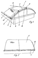
- a shading system 1 is mounted on a light band 2 that in plan view is rectangular and can be mounted on a roof of a building.
- the shading system 1 comprises on opposite sides of the light strip 2 arranged longitudinal struts 3, which as a hollow profile made of metal, for example aluminum are trained.
- the longitudinal struts 3 are with a supporting structure 4 of the Light strip 2 screwed. Between the two longitudinal struts 3 are regular Intermediate struts 8 also on the support structure 4th established.
- the supporting structure 4 of the light strip 2 is mounted on an attachment 5, which can be fixed to a building roof in a sealed manner.
- a plate 6 is stretched on the longitudinal struts 3 and the central struts 8, in the light openings 7 are recessed.
- the plate 6 consists of a metal sheet with a thickness between 1 and 5 mm, preferably about 2 mm and has light openings 11, which take a regular pattern.
- the light openings 11 take about an area of 20 to in relation to the base of the plate 6 70%, preferably 35 to 45%.
- the plate 6 On the longitudinal struts 3, the plate 6 is held in a receptacle, which consists of a Bar 7 and the longitudinal strut 3 arranged underneath are formed, the plate 6 is received in the space.
- the bar 7 is L-shaped, with one leg of the L approximately the width of the Longitudinal strut 3 and the plate 6 fixes and the second leg bears on the side surface of the longitudinal strut 3 and is screwed to it.
- the upper leg of the bar 7 is also screwed, wherein the screw passes through the bar 7, the plate 6 and the longitudinal strut 3. Due to the width of the leg of the bar 7, the plate 6 can with a certain Play in the receptacle between the bar 7 and the longitudinal strut 3 so that assembly is simplified due to a possible tolerance compensation.
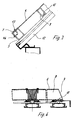
- FIG 3 schematically shows the fastening by means of screws 13 and 14.
- Screws 15 are used to fasten the longitudinal struts 3 and the central struts 8 through a bottom wall of the longitudinal strut 3 and cross strut designed as a hollow profile 8 carried out with a cross strut 12 of the supporting structure 4 of the Light strip 2 are screwed.
- an end face 9 of the longitudinal strut 3 and Center strut 8 is formed obliquely so that the screw 15 arranged on the edge is accessible from above.
- the end face 9 of the longitudinal struts 3 and center struts 8 can then be sealed by a cover.
- the plate 6 is only loosely on the center struts 8 and can heat up if heated accordingly therefore bulge so that no thermal stresses are derived from the supporting structure 4 Need to become.
- FIG. 5 shows a further exemplary embodiment in which the plate 6 takes place arched flat on two longitudinal struts 3 and a central strut 8 is mounted.
- the Longitudinal struts 3 and the central struts 8 can on a support structure 4 in the can be attached previously shown.
- FIG. 6 A further embodiment is shown in FIG. 6, in which the plate 6 is kinked is trained.
- the plate 6 is otherwise in the aforementioned manner strip-shaped bar 7 and screws 13 fixed to longitudinal struts 3.
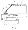
- FIG. 8 shows a modified embodiment of a shading system, in which a seal 20 is mounted on a central strut 8.
- the seal 20 is plate-shaped and covers the front edge of the central strut 8, wherein a slot 21 is formed on the seal 20, into which the plate 6 is inserted.
- the seal 20 lies loosely on a profile 23 so that the liquid can flow out at the obliquely arranged seal 20.
- the seal 20 takes over the function of soundproofing and can for a provide some compensation for thermal expansion of the components.
- the Seal 20 can be spanned continuously between the support profiles.
- the invention shown is not limited to the exemplary embodiments shown.
- the shape of the plate 6 can be both in width and in terms of Recesses 11 can be chosen freely.
- the width of the plate 6 be dimensioned so that it can be unwound from a roll and only in the desired length must be separated.
- angle profiles has the advantage that they are easier Manufacturing facilitate assembly and in particular the longitudinal struts 3 and center struts 8 and 9 can be screwed laterally in a central area. Furthermore, the angles on the support structure or the longitudinal struts 3 or Center struts 8 and 9 are pre-assembled.
Landscapes
- Engineering & Computer Science (AREA)
- Structural Engineering (AREA)
- Architecture (AREA)
- Civil Engineering (AREA)
- Roof Covering Using Slabs Or Stiff Sheets (AREA)
- Non-Portable Lighting Devices Or Systems Thereof (AREA)
- Valve Device For Special Equipments (AREA)
- Control Of Throttle Valves Provided In The Intake System Or In The Exhaust System (AREA)
- Spray Control Apparatus (AREA)
Abstract
Description
- Figur 1
- eine perspektivische Ansicht eines erfindungsgemäßen Beschattungssystems im montierten Zustand;
- Figur 2
- eine weitere perspektivische Ansicht des Beschattungssystems der Figur 1;
- Figur 3
- eine geschnittene Detailansicht des Beschattungssystems der Figur 1;
- Figur 4
- eine geschnittene Ansicht auf eine Mittelstrebe des Beschattungssystems der Figur 3;
- Figur 5
- eine Ansicht auf ein weiteres Ausführungsbeispiel eines erfindungsgemäßen Beschattungssystems;
- Figur 6
- eine Ansicht einer weiteren Ausführungsform eines erfindungsgemäßen Beschattungssystems;
- Figur 7
- eine Detailansicht auf die Platte des Beschattungssystems, und
- Figur 8
- eine Detailansicht eines modifizierten Beschattungssystems.
Claims (12)
- Beschattungssystem (1) für ein Lichtband (2) oder eine Lichtkuppel, mit zwei an gegenüberliegenden Seiten angeordneten Längsstreben (3), die mit einer Tragkonstruktion (4) eines Lichtbandes (2) oder einer Lichtkuppel verschraubbar sind, dadurch gekennzeichnet, dass zwischen den Längsstreben (3) eine mit Lichtöffnungen (11) versehene Platte (6) aufgespannt ist und die Platte (6) klemmend an den Längsstreben (3) festgelegt ist.
- Beschattungssystem nach Anspruch 1, dadurch gekennzeichnet, dass die Platte (6) randseitig jeweils in einer Aufnahme zwischen einer Leiste (7) und einer Längsstrebe (3) gehalten ist.
- Beschattungssystem nach Anspruch 2, dadurch gekennzeichnet, dass sich die Leiste (7) etwa über die Breite der Längsstrebe (3) erstreckt.
- Beschattungssystem nach Anspruch 2 oder 3, dadurch gekennzeichnet, dass die Leiste (7) als Winkelprofil ausgebildet ist, das mit einem Schenkel die Platte (6) randseitig überdeckt und mit einem zweiten Schenkel mit der Längsstrebe (3) verschraubt ist.
- Beschattungssystem nach einem der Ansprüche 1 bis 4, dadurch gekennzeichnet, dass zwischen den Seitlichen Längsstreben (3) ein oder mehrere parallel zu den Längsstreben (3) angeordnete Mittelstreben (8) zur Abstützung der Platte (6) montiert sind.
- Beschattungssystem nach Anspruch 5, dadurch gekennzeichnet, dass die Platte (6) auf der oder den Mittelstreben (8) nur lose aufgelegt ist.
- Beschattungssystem nach einem der Ansprüche 1 bis 6, dadurch gekennzeichnet, dass die Längsstreben (3) und/oder die Mittelstreben (8) als Hohlprofil ausgebildet sind.
- Beschattungssystem nach Anspruch 7, dadurch gekennzeichnet, dass die Längsstreben (3) und/oder die Mittelstreben (8) eine nach oben schräg verlaufende Stirnseite (9) aufweisen und eine an einer Tragkonstruktion anliegende Wand (10) der Längsstrebe (3) und/oder der Mittelstrebe (8) von oben zugänglich ist.
- Beschattungssystem nach Anspruch 7 oder 8, dadurch gekennzeichnet, dass die Stirnseiten der Längsstreben (3) und/oder der Mittelstreben (8) mit einer Abdeckung verschlossen sind.
- Beschattungssystem nach einem der Ansprüche 1 bis 9, dadurch gekennzeichnet, dass die Längsstreben (3) und/oder die Mittelstreben (8) mit Querstreben (12) der Tragkonstruktion (4) des Lichtbandes (2) oder der Lichtkuppel verschraubt sind.
- Beschattungssystem nach einem der Ansprüche 1 bis 10, dadurch gekennzeichnet, dass die mit Lichtöffnungen (11) versehene Platte (6) aus Metall besteht.
- Beschattungssystem nach einem der Ansprüche 1 bis 11, dadurch gekennzeichnet, dass die Lichtöffnungen (11) in der Platte (6) ein regelmäßiges Muster ausbilden und im Verhältnis zur Grundfläche eine Fläche von 20 bis 70 %, vorzugsweise 35 bis 45 %, einnehmen.
Applications Claiming Priority (2)
| Application Number | Priority Date | Filing Date | Title |
|---|---|---|---|
| DE20303157U | 2003-02-27 | ||
| DE20303157U DE20303157U1 (de) | 2003-02-27 | 2003-02-27 | Beschattungssystem |
Publications (2)
| Publication Number | Publication Date |
|---|---|
| EP1452661A1 true EP1452661A1 (de) | 2004-09-01 |
| EP1452661B1 EP1452661B1 (de) | 2006-08-09 |
Family
ID=7980386
Family Applications (1)
| Application Number | Title | Priority Date | Filing Date |
|---|---|---|---|
| EP04003024A Expired - Lifetime EP1452661B1 (de) | 2003-02-27 | 2004-02-11 | Beschattungssystem |
Country Status (5)
| Country | Link |
|---|---|
| EP (1) | EP1452661B1 (de) |
| AT (1) | ATE335891T1 (de) |
| DE (2) | DE20303157U1 (de) |
| ES (1) | ES2270195T3 (de) |
| PT (1) | PT1452661E (de) |
Cited By (3)
| Publication number | Priority date | Publication date | Assignee | Title |
|---|---|---|---|---|
| ES2328199A1 (es) * | 2007-03-15 | 2009-11-10 | Vicris, S.L. | Estructura para la proteccion de claraboyas. |
| JP2010516926A (ja) * | 2007-01-23 | 2010-05-20 | ジャック ピジェル、 | 熱と風に対する建築物の防護シールド |
| CN101793849B (zh) * | 2009-12-29 | 2012-03-21 | 中国建筑材料检验认证中心 | 利用导入太阳光的建筑遮阳装置节能效果测定设备及检测方法 |
Families Citing this family (2)
| Publication number | Priority date | Publication date | Assignee | Title |
|---|---|---|---|---|
| DE20313025U1 (de) | 2003-08-21 | 2003-10-30 | Essmann GmbH & Co. KG, 32107 Bad Salzuflen | Beschattungssystem |
| DE202008000004U1 (de) * | 2008-02-13 | 2009-03-26 | Jet Tageslicht & Rwa Gmbh | Sonnenschutzvorrichtung zur Beschattung von Lichtbändern |
Citations (7)
| Publication number | Priority date | Publication date | Assignee | Title |
|---|---|---|---|---|
| US1112401A (en) * | 1912-05-08 | 1914-09-29 | Claude J Allen | Roof-window. |
| DE1708784A1 (de) * | 1959-04-28 | 1970-08-27 | Eberspaecher J | Sicherung gegen das Herabfallen von Teilen einer gebrochenen gewoelbten Silikatglasscheibe zur Abdeckung von Oberlichtoeffnungen |
| FR2151165A5 (de) * | 1971-08-23 | 1973-04-13 | Goutte Toquet Ets | |
| US5237788A (en) * | 1991-10-31 | 1993-08-24 | Kiyoshi Sandow | Skylight guard assembly |
| FR2705985A1 (fr) * | 1993-06-01 | 1994-12-09 | Innovation Partners | Système d'éclairage zénithal destiné à être disposé dans une ouverture ménagée dans une toiture. |
| US6209271B1 (en) * | 1998-11-30 | 2001-04-03 | John C. Kovacs | Safety screen with a guard assembly having three flanged mounting members |
| GB2374095A (en) * | 2001-04-05 | 2002-10-09 | Silent Roofs Ltd | Reducing noise of precipitation on roofs |
Family Cites Families (3)
| Publication number | Priority date | Publication date | Assignee | Title |
|---|---|---|---|---|
| DE8002069U1 (de) | 1980-01-26 | 1980-04-24 | Heinz Essmann Gmbh & Co Kg, 4902 Bad Salzuflen | Nordlichtkuppel |
| DE19708174C1 (de) | 1996-07-06 | 1998-02-12 | Engelbert Hollah | Sonnenschutz |
| DE20012164U1 (de) | 2000-07-13 | 2000-12-07 | Kaefer Isoliertechnik GmbH & Co KG, 28195 Bremen | Folienabsorber, insbesondere zum inneren Einsatz vor verglasten Außenflächen |
-
2003
- 2003-02-27 DE DE20303157U patent/DE20303157U1/de not_active Expired - Lifetime
-
2004
- 2004-02-11 DE DE502004001123T patent/DE502004001123D1/de not_active Expired - Lifetime
- 2004-02-11 AT AT04003024T patent/ATE335891T1/de not_active IP Right Cessation
- 2004-02-11 PT PT04003024T patent/PT1452661E/pt unknown
- 2004-02-11 ES ES04003024T patent/ES2270195T3/es not_active Expired - Lifetime
- 2004-02-11 EP EP04003024A patent/EP1452661B1/de not_active Expired - Lifetime
Patent Citations (7)
| Publication number | Priority date | Publication date | Assignee | Title |
|---|---|---|---|---|
| US1112401A (en) * | 1912-05-08 | 1914-09-29 | Claude J Allen | Roof-window. |
| DE1708784A1 (de) * | 1959-04-28 | 1970-08-27 | Eberspaecher J | Sicherung gegen das Herabfallen von Teilen einer gebrochenen gewoelbten Silikatglasscheibe zur Abdeckung von Oberlichtoeffnungen |
| FR2151165A5 (de) * | 1971-08-23 | 1973-04-13 | Goutte Toquet Ets | |
| US5237788A (en) * | 1991-10-31 | 1993-08-24 | Kiyoshi Sandow | Skylight guard assembly |
| FR2705985A1 (fr) * | 1993-06-01 | 1994-12-09 | Innovation Partners | Système d'éclairage zénithal destiné à être disposé dans une ouverture ménagée dans une toiture. |
| US6209271B1 (en) * | 1998-11-30 | 2001-04-03 | John C. Kovacs | Safety screen with a guard assembly having three flanged mounting members |
| GB2374095A (en) * | 2001-04-05 | 2002-10-09 | Silent Roofs Ltd | Reducing noise of precipitation on roofs |
Cited By (4)
| Publication number | Priority date | Publication date | Assignee | Title |
|---|---|---|---|---|
| JP2010516926A (ja) * | 2007-01-23 | 2010-05-20 | ジャック ピジェル、 | 熱と風に対する建築物の防護シールド |
| CN101668909B (zh) * | 2007-01-23 | 2012-07-18 | 雅克·皮热尔 | 建筑物用防热防风防护板 |
| ES2328199A1 (es) * | 2007-03-15 | 2009-11-10 | Vicris, S.L. | Estructura para la proteccion de claraboyas. |
| CN101793849B (zh) * | 2009-12-29 | 2012-03-21 | 中国建筑材料检验认证中心 | 利用导入太阳光的建筑遮阳装置节能效果测定设备及检测方法 |
Also Published As
| Publication number | Publication date |
|---|---|
| DE20303157U1 (de) | 2003-04-30 |
| ES2270195T3 (es) | 2007-04-01 |
| DE502004001123D1 (de) | 2006-09-21 |
| EP1452661B1 (de) | 2006-08-09 |
| PT1452661E (pt) | 2006-12-29 |
| ATE335891T1 (de) | 2006-09-15 |
Similar Documents
| Publication | Publication Date | Title |
|---|---|---|
| DE102007027997B4 (de) | Befestigungseinrichtung für an einem Gestellaufbau anzuordnende flächige rahmenlose Bauteile, insbesondere Solarmodule | |
| DE10047400C2 (de) | Photovoltaische Solarvorrichtung | |
| DE2846275C2 (de) | ||
| DE102007033323B4 (de) | Befestigungseinrichtung für an einem Gestellaufbau anzuordnende flächige Bauteile, insbesondere Solarmodule | |
| DE3042952C2 (de) | ||
| DE9010696U1 (de) | Solarvorrichtung | |
| DE29809280U1 (de) | Halterung von Solarmodulen | |
| DE29606547U1 (de) | Anordnung zur Befestigung von Solarmodulen auf einem Dach | |
| DE2758067A1 (de) | Solarkollektoranlage | |
| EP1452661B1 (de) | Beschattungssystem | |
| DE9016706U1 (de) | Belichtungsvorrichtung | |
| DE202023104047U1 (de) | Ersatzdachziegel | |
| DE69116161T3 (de) | Trägerrinne für gewächshäuser | |
| EP0231485A2 (de) | Dachabdeckungsbaustein | |
| DE19734346A1 (de) | Dachdurchdringungs-Einfassung | |
| DE9207858U1 (de) | Dachrinne | |
| DE4131460C2 (de) | Randeinfassung für ein Flachdach oder einen Balkon | |
| DE19943525C2 (de) | Glas-Fassadenbekleidungen mit einer Befestigungsvorrichtung | |
| DE102021000457A1 (de) | Rahmenprofilelement eines Rahmens für ein plattenförmiges Solarmodul und Indachsolaranlage | |
| DE19912143A1 (de) | Bauteilset zum Bau eines Gewächshauses | |
| DE2837147C2 (de) | ||
| DE3720778C2 (de) | ||
| DE2947956A1 (de) | Sonnenkollektor | |
| EP0403609B1 (de) | Aus elastischem material bestehender umfassungsrahmen für ein flächiges element | |
| DE3401270C2 (de) | Firsteinleger für Dachpfannen mit Kopfverfalzung |
Legal Events
| Date | Code | Title | Description |
|---|---|---|---|
| PUAI | Public reference made under article 153(3) epc to a published international application that has entered the european phase |
Free format text: ORIGINAL CODE: 0009012 |
|
| AK | Designated contracting states |
Kind code of ref document: A1 Designated state(s): AT BE BG CH CY CZ DE DK EE ES FI FR GB GR HU IE IT LI LU MC NL PT RO SE SI SK TR |
|
| AX | Request for extension of the european patent |
Extension state: AL LT LV MK |
|
| RIN1 | Information on inventor provided before grant (corrected) |
Inventor name: HEINRICHS, HEINRICH Inventor name: KETTLER, JOSEF |
|
| 17P | Request for examination filed |
Effective date: 20050225 |
|
| AKX | Designation fees paid |
Designated state(s): AT BE BG CH CY CZ DE DK EE ES FI FR GB GR HU IE IT LI LU MC NL PT RO SE SI SK TR |
|
| 17Q | First examination report despatched |
Effective date: 20050429 |
|
| GRAP | Despatch of communication of intention to grant a patent |
Free format text: ORIGINAL CODE: EPIDOSNIGR1 |
|
| GRAS | Grant fee paid |
Free format text: ORIGINAL CODE: EPIDOSNIGR3 |
|
| GRAA | (expected) grant |
Free format text: ORIGINAL CODE: 0009210 |
|
| AK | Designated contracting states |
Kind code of ref document: B1 Designated state(s): AT BE BG CH CY CZ DE DK EE ES FI FR GB GR HU IE IT LI LU MC NL PT RO SE SI SK TR |
|
| PG25 | Lapsed in a contracting state [announced via postgrant information from national office to epo] |
Ref country code: IT Free format text: LAPSE BECAUSE OF FAILURE TO SUBMIT A TRANSLATION OF THE DESCRIPTION OR TO PAY THE FEE WITHIN THE PRESCRIBED TIME-LIMIT;WARNING: LAPSES OF ITALIAN PATENTS WITH EFFECTIVE DATE BEFORE 2007 MAY HAVE OCCURRED AT ANY TIME BEFORE 2007. THE CORRECT EFFECTIVE DATE MAY BE DIFFERENT FROM THE ONE RECORDED. Effective date: 20060809 Ref country code: CZ Free format text: LAPSE BECAUSE OF FAILURE TO SUBMIT A TRANSLATION OF THE DESCRIPTION OR TO PAY THE FEE WITHIN THE PRESCRIBED TIME-LIMIT Effective date: 20060809 Ref country code: IE Free format text: LAPSE BECAUSE OF FAILURE TO SUBMIT A TRANSLATION OF THE DESCRIPTION OR TO PAY THE FEE WITHIN THE PRESCRIBED TIME-LIMIT Effective date: 20060809 Ref country code: FI Free format text: LAPSE BECAUSE OF FAILURE TO SUBMIT A TRANSLATION OF THE DESCRIPTION OR TO PAY THE FEE WITHIN THE PRESCRIBED TIME-LIMIT Effective date: 20060809 Ref country code: SI Free format text: LAPSE BECAUSE OF FAILURE TO SUBMIT A TRANSLATION OF THE DESCRIPTION OR TO PAY THE FEE WITHIN THE PRESCRIBED TIME-LIMIT Effective date: 20060809 Ref country code: RO Free format text: LAPSE BECAUSE OF FAILURE TO SUBMIT A TRANSLATION OF THE DESCRIPTION OR TO PAY THE FEE WITHIN THE PRESCRIBED TIME-LIMIT Effective date: 20060809 Ref country code: SK Free format text: LAPSE BECAUSE OF FAILURE TO SUBMIT A TRANSLATION OF THE DESCRIPTION OR TO PAY THE FEE WITHIN THE PRESCRIBED TIME-LIMIT Effective date: 20060809 |
|
| REG | Reference to a national code |
Ref country code: GB Ref legal event code: FG4D Free format text: NOT ENGLISH |
|
| REG | Reference to a national code |
Ref country code: CH Ref legal event code: EP |
|
| REG | Reference to a national code |
Ref country code: IE Ref legal event code: FG4D Free format text: LANGUAGE OF EP DOCUMENT: GERMAN |
|
| REF | Corresponds to: |
Ref document number: 502004001123 Country of ref document: DE Date of ref document: 20060921 Kind code of ref document: P |
|
| PG25 | Lapsed in a contracting state [announced via postgrant information from national office to epo] |
Ref country code: BG Free format text: LAPSE BECAUSE OF FAILURE TO SUBMIT A TRANSLATION OF THE DESCRIPTION OR TO PAY THE FEE WITHIN THE PRESCRIBED TIME-LIMIT Effective date: 20061109 Ref country code: SE Free format text: LAPSE BECAUSE OF FAILURE TO SUBMIT A TRANSLATION OF THE DESCRIPTION OR TO PAY THE FEE WITHIN THE PRESCRIBED TIME-LIMIT Effective date: 20061109 Ref country code: DK Free format text: LAPSE BECAUSE OF FAILURE TO SUBMIT A TRANSLATION OF THE DESCRIPTION OR TO PAY THE FEE WITHIN THE PRESCRIBED TIME-LIMIT Effective date: 20061109 |
|
| GBT | Gb: translation of ep patent filed (gb section 77(6)(a)/1977) |
Effective date: 20061108 |
|
| RAP2 | Party data changed (patent owner data changed or rights of a patent transferred) |
Owner name: ESSMANN GMBH |
|
| REG | Reference to a national code |
Ref country code: PT Ref legal event code: SC4A Free format text: AVAILABILITY OF NATIONAL TRANSLATION Effective date: 20061103 |
|
| NLT1 | Nl: modifications of names registered in virtue of documents presented to the patent office pursuant to art. 16 a, paragraph 1 |
Owner name: ESSMANN GMBH |
|
| REG | Reference to a national code |
Ref country code: PT Ref legal event code: PD4A Owner name: ESSMANN GMBH, DE Effective date: 20061122 |
|
| NLT2 | Nl: modifications (of names), taken from the european patent patent bulletin |
Owner name: ESSMANN GMBH Effective date: 20061129 |
|
| PG25 | Lapsed in a contracting state [announced via postgrant information from national office to epo] |
Ref country code: MC Free format text: LAPSE BECAUSE OF NON-PAYMENT OF DUE FEES Effective date: 20070228 |
|
| ET | Fr: translation filed | ||
| REG | Reference to a national code |
Ref country code: IE Ref legal event code: FD4D |
|
| REG | Reference to a national code |
Ref country code: ES Ref legal event code: FG2A Ref document number: 2270195 Country of ref document: ES Kind code of ref document: T3 |
|
| PLBE | No opposition filed within time limit |
Free format text: ORIGINAL CODE: 0009261 |
|
| STAA | Information on the status of an ep patent application or granted ep patent |
Free format text: STATUS: NO OPPOSITION FILED WITHIN TIME LIMIT |
|
| 26N | No opposition filed |
Effective date: 20070510 |
|
| BECN | Be: change of holder's name |
Owner name: *ESSMANN G.M.B.H. Effective date: 20060809 |
|
| PG25 | Lapsed in a contracting state [announced via postgrant information from national office to epo] |
Ref country code: GR Free format text: LAPSE BECAUSE OF FAILURE TO SUBMIT A TRANSLATION OF THE DESCRIPTION OR TO PAY THE FEE WITHIN THE PRESCRIBED TIME-LIMIT Effective date: 20061110 |
|
| PG25 | Lapsed in a contracting state [announced via postgrant information from national office to epo] |
Ref country code: AT Free format text: LAPSE BECAUSE OF NON-PAYMENT OF DUE FEES Effective date: 20070211 |
|
| PG25 | Lapsed in a contracting state [announced via postgrant information from national office to epo] |
Ref country code: EE Free format text: LAPSE BECAUSE OF FAILURE TO SUBMIT A TRANSLATION OF THE DESCRIPTION OR TO PAY THE FEE WITHIN THE PRESCRIBED TIME-LIMIT Effective date: 20060809 |
|
| PGRI | Patent reinstated in contracting state [announced from national office to epo] |
Ref country code: IT Effective date: 20080601 |
|
| REG | Reference to a national code |
Ref country code: CH Ref legal event code: PL |
|
| PG25 | Lapsed in a contracting state [announced via postgrant information from national office to epo] |
Ref country code: CH Free format text: LAPSE BECAUSE OF NON-PAYMENT OF DUE FEES Effective date: 20080229 Ref country code: LI Free format text: LAPSE BECAUSE OF NON-PAYMENT OF DUE FEES Effective date: 20080229 |
|
| REG | Reference to a national code |
Ref country code: CH Ref legal event code: AEN Free format text: WEITERBEHANDLUNG GUTGEHEISSEN |
|
| PGRI | Patent reinstated in contracting state [announced from national office to epo] |
Ref country code: CH Effective date: 20081111 |
|
| PG25 | Lapsed in a contracting state [announced via postgrant information from national office to epo] |
Ref country code: CY Free format text: LAPSE BECAUSE OF FAILURE TO SUBMIT A TRANSLATION OF THE DESCRIPTION OR TO PAY THE FEE WITHIN THE PRESCRIBED TIME-LIMIT Effective date: 20060809 Ref country code: LU Free format text: LAPSE BECAUSE OF NON-PAYMENT OF DUE FEES Effective date: 20070211 |
|
| PG25 | Lapsed in a contracting state [announced via postgrant information from national office to epo] |
Ref country code: TR Free format text: LAPSE BECAUSE OF FAILURE TO SUBMIT A TRANSLATION OF THE DESCRIPTION OR TO PAY THE FEE WITHIN THE PRESCRIBED TIME-LIMIT Effective date: 20060809 Ref country code: HU Free format text: LAPSE BECAUSE OF FAILURE TO SUBMIT A TRANSLATION OF THE DESCRIPTION OR TO PAY THE FEE WITHIN THE PRESCRIBED TIME-LIMIT Effective date: 20070210 |
|
| PGFP | Annual fee paid to national office [announced via postgrant information from national office to epo] |
Ref country code: NL Payment date: 20140220 Year of fee payment: 11 |
|
| PGFP | Annual fee paid to national office [announced via postgrant information from national office to epo] |
Ref country code: IT Payment date: 20140226 Year of fee payment: 11 Ref country code: FR Payment date: 20140218 Year of fee payment: 11 Ref country code: ES Payment date: 20140220 Year of fee payment: 11 Ref country code: BE Payment date: 20140219 Year of fee payment: 11 |
|
| PGFP | Annual fee paid to national office [announced via postgrant information from national office to epo] |
Ref country code: PT Payment date: 20140130 Year of fee payment: 11 |
|
| PGFP | Annual fee paid to national office [announced via postgrant information from national office to epo] |
Ref country code: DE Payment date: 20150302 Year of fee payment: 12 Ref country code: CH Payment date: 20150325 Year of fee payment: 12 |
|
| PGFP | Annual fee paid to national office [announced via postgrant information from national office to epo] |
Ref country code: GB Payment date: 20150324 Year of fee payment: 12 |
|
| PG25 | Lapsed in a contracting state [announced via postgrant information from national office to epo] |
Ref country code: BE Free format text: LAPSE BECAUSE OF NON-PAYMENT OF DUE FEES Effective date: 20150228 |
|
| REG | Reference to a national code |
Ref country code: PT Ref legal event code: MM4A Free format text: LAPSE DUE TO NON-PAYMENT OF FEES Effective date: 20150811 |
|
| REG | Reference to a national code |
Ref country code: NL Ref legal event code: V1 Effective date: 20150901 |
|
| PG25 | Lapsed in a contracting state [announced via postgrant information from national office to epo] |
Ref country code: NL Free format text: LAPSE BECAUSE OF NON-PAYMENT OF DUE FEES Effective date: 20150901 |
|
| PG25 | Lapsed in a contracting state [announced via postgrant information from national office to epo] |
Ref country code: PT Free format text: LAPSE BECAUSE OF NON-PAYMENT OF DUE FEES Effective date: 20150811 |
|
| REG | Reference to a national code |
Ref country code: FR Ref legal event code: ST Effective date: 20151030 |
|
| PG25 | Lapsed in a contracting state [announced via postgrant information from national office to epo] |
Ref country code: IT Free format text: LAPSE BECAUSE OF FAILURE TO SUBMIT A TRANSLATION OF THE DESCRIPTION OR TO PAY THE FEE WITHIN THE PRESCRIBED TIME-LIMIT Effective date: 20150211 |
|
| PG25 | Lapsed in a contracting state [announced via postgrant information from national office to epo] |
Ref country code: FR Free format text: LAPSE BECAUSE OF NON-PAYMENT OF DUE FEES Effective date: 20150302 |
|
| REG | Reference to a national code |
Ref country code: DE Ref legal event code: R119 Ref document number: 502004001123 Country of ref document: DE |
|
| REG | Reference to a national code |
Ref country code: ES Ref legal event code: FD2A Effective date: 20160929 |
|
| REG | Reference to a national code |
Ref country code: CH Ref legal event code: PL |
|
| GBPC | Gb: european patent ceased through non-payment of renewal fee |
Effective date: 20160211 |
|
| PG25 | Lapsed in a contracting state [announced via postgrant information from national office to epo] |
Ref country code: LI Free format text: LAPSE BECAUSE OF NON-PAYMENT OF DUE FEES Effective date: 20160229 Ref country code: CH Free format text: LAPSE BECAUSE OF NON-PAYMENT OF DUE FEES Effective date: 20160229 |
|
| PG25 | Lapsed in a contracting state [announced via postgrant information from national office to epo] |
Ref country code: ES Free format text: LAPSE BECAUSE OF NON-PAYMENT OF DUE FEES Effective date: 20150212 |
|
| PG25 | Lapsed in a contracting state [announced via postgrant information from national office to epo] |
Ref country code: GB Free format text: LAPSE BECAUSE OF NON-PAYMENT OF DUE FEES Effective date: 20160211 Ref country code: DE Free format text: LAPSE BECAUSE OF NON-PAYMENT OF DUE FEES Effective date: 20160901 |