EP1452665A1 - Holzfussbodensystem - Google Patents
Holzfussbodensystem Download PDFInfo
- Publication number
- EP1452665A1 EP1452665A1 EP03100449A EP03100449A EP1452665A1 EP 1452665 A1 EP1452665 A1 EP 1452665A1 EP 03100449 A EP03100449 A EP 03100449A EP 03100449 A EP03100449 A EP 03100449A EP 1452665 A1 EP1452665 A1 EP 1452665A1
- Authority
- EP
- European Patent Office
- Prior art keywords
- boards
- base
- support
- wing
- wings
- Prior art date
- Legal status (The legal status is an assumption and is not a legal conclusion. Google has not performed a legal analysis and makes no representation as to the accuracy of the status listed.)
- Granted
Links
Images
Classifications
-
- E—FIXED CONSTRUCTIONS
- E04—BUILDING
- E04F—FINISHING WORK ON BUILDINGS, e.g. STAIRS, FLOORS
- E04F15/00—Flooring
- E04F15/02—Flooring or floor layers composed of a number of similar elements
- E04F15/04—Flooring or floor layers composed of a number of similar elements only of wood or with a top layer of wood, e.g. with wooden or metal connecting members
-
- E—FIXED CONSTRUCTIONS
- E04—BUILDING
- E04F—FINISHING WORK ON BUILDINGS, e.g. STAIRS, FLOORS
- E04F15/00—Flooring
- E04F15/02—Flooring or floor layers composed of a number of similar elements
- E04F15/02044—Separate elements for fastening to an underlayer
- E04F2015/0205—Separate elements for fastening to an underlayer with load-supporting elongated furring elements between the flooring elements and the underlayer
- E04F2015/02066—Separate elements for fastening to an underlayer with load-supporting elongated furring elements between the flooring elements and the underlayer with additional fastening elements between furring elements and flooring elements
- E04F2015/02077—Separate elements for fastening to an underlayer with load-supporting elongated furring elements between the flooring elements and the underlayer with additional fastening elements between furring elements and flooring elements the additional fastening elements located in-between two adjacent flooring elements
- E04F2015/02094—Engaging side grooves running along the whole length of the flooring elements
-
- E—FIXED CONSTRUCTIONS
- E04—BUILDING
- E04F—FINISHING WORK ON BUILDINGS, e.g. STAIRS, FLOORS
- E04F2201/00—Joining sheets or plates or panels
- E04F2201/05—Separate connectors or inserts, e.g. pegs, pins, keys or strips
- E04F2201/0511—Strips or bars, e.g. nailing strips
Definitions
- the invention relates to a wooden floor system comprising at least two wooden boards capable of being placed side by side and each having edges which are provided with grooves extending in the direction of the length of the boards; and at least one piece for fixing the boards to a support, each piece having a U-shaped profile, forming a base and two branches; at the top of each of the branches being a wing oriented towards the outside of the U, capable of being inserted into the groove of one of the boards; each wing forming at rest an angle u less than 90 degrees relative to the branch at the top of which it is located; each piece at rest defining a difference in height h 1 between the lowest point of each of its wings and its base, and a difference in height h 2 between the top of each of its branches and its base; each piece further defining, when the boards are fixed to the support by the at least one piece, a difference in height h 3 between the lowest point of each of its wings and its base; each height difference h 1 being smaller than the corresponding height difference h 3 .
- Such wooden floor systems are well known in the state of the art and present a number benefits.
- the first is that the means are not or hardly visible once the assembled floor system while allowing arrangement with a small spacing between them planks side by side, which is an advantage aesthetic sought.
- the non-visible fasteners are often qualified invisible, even if, from a certain angle, the pieces fasteners can be seen through the gap planks.
- the second advantage is that the boards must not be pierced or crossed by fastening means such as nails or screws, which prevents any infiltration or rising of water by capillary action which could cause rapid deterioration of the wood and unwanted degradation of the floor. This second advantage is particularly important in the case of wooden floor system for outdoor patio, where the presence of water due for example to rain can be abundant.
- the floor system as described in the request EP 1106842 A1 presents several problems. On the one hand, it reacts badly to contractions and wood expansions. On the other hand, the mounting operation of it is complex.
- the object of the invention is to provide a system of wooden floor which, on the one hand, does not generally present, under conditions of normal use, no play between wings of the fastener and the boards, nor tearing of the wings, nor detachment of the piece of fixation or planks, following contractions or wood expansions over time, and of which, apart, the assembly operation is simple.
- the wooden floor system according to the invention is characterized in that, when the boards are fixed to the support by at least one piece, each wing is supported in the groove of one of the boards substantially in one point and each height difference h 3 is smaller than the corresponding height difference h 2 .
- the third problem of the floor system described in European patent application EP 1106842 A1 is the complexity of the assembly operation thereof. Indeed, after partially tightening the screws, install the wooden slats between rows of screws partially screwed, insert the fixing parts by making them slide inside the grooves and around the screw and finally complete the screwing with a special tool until a sufficient blocking of the boards by the part. That constitutes a delicate process, which further comprises, at least in the particular realization of the document floor system of the state of the art cited in which the edges of the grooves are inclined downwards and the wings towards the high, an additional difficulty.
- the wooden floor system according to the invention when the boards are fixed to the support by at least a part, i.e. once the assembly operation of the system completed, the wooden floor system according to the invention is such that each wing, having undergone during the mounting an elastic deformation, having caused it to be oriented at an angle greater than the angle it had at rest, tends to return to the orientation it had at rest and, in this way, exerts a retaining force towards bottom and clamp the part of the board under the groove on which said wing bears.
- the elasticity of each wing i.e. the fact that it is deformable and not rigid, allows to block a board between its support and the fulcrum of said wing without play possible, even after expansion or wood contraction to some extent.
- each wing and its tendency to return to its original orientation generates a force which can only be exerted by the existence of an arm lever going from the top of the corresponding branch of the U, that is to say the one to which said wing is attached, at the fulcrum of said wing in the groove corresponding, i.e. the one on which the wing relies.
- the lever arm and the associated bending moment generate a force thanks to the fact that each wing takes support in a groove substantially at a point, this support point being preferably quite far from the top of the branch of the U, even at the end of the wing.
- a combination of complementary elements is necessary for the desired blocking effect of the boards under the effect of the elasticity of the wings can be correctly obtained.
- each difference in height h 3 is smaller than the corresponding height difference h 2 .
- the grooves of the boards have a chamfer for easy insertion wings during assembly.
- the assembly operation of the wooden floor system according to the invention is found simplified thanks to that.
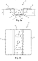
- Fig. 1a shows a schematic representation of the profile of an example of a fixing part (2) at rest of the wooden floor system according to the invention.
- Profile of said fixing piece (2) is U-shaped, the U comprising a base (4) and two branches (6).
- At the end of each branch (6) of the U is a wing (8) oriented towards outside the U and forming an angle, respectively identified by u and u 'for each of the two wings (8), less than 90 degrees to the branch (6) corresponding.
- an opening (10) is provided. in the base (4) of the part (2), intended for the passage of fixing means (12) of the part (2) to the support (18). he will be clear to those skilled in the art that although the presence of this opening (10) constitutes a preferred solution, a similar solution without opening is possible.
- fixing means (12) any element allowing to make substantially integral the piece of fixing (2) and the support (18) in conditions normal use.
- These fixing means (12) can for example be one or more screws, one or more nails, one or staples or any other means of attachment, even if the presence of a screw is the preferred solution to avoid that the base (4) of the fixing piece (2) does not lift under the effect of the expansion of the wood which would act at the like a crowbar.
- the total area of the surface formed by the at least one opening (10) in the surface of the base (4) is preferably as small as possible for guarantee sufficient rigidity of the base (4) of the part (2) for the reasons mentioned above.
- said total area is advantageously less than one quarter of the surface area of said base (4).
- through the base (4) of each piece (2) is only one opening (10).
- This opening (10) is therefore preferably small and compact, that is to say for example substantially circular, advantageously less than 10 mm in diameter, even less than 8 mm or a diameter equal to about 5 mm.
- said support (18), meanwhile, or supporting structure of the floor can for example consist of a plurality joists, rafters or any base, possibly pre-drilled for the passage of the means of fixing (12), and comprising a metallic frame or not.
- the joists are preferably made of wood among tatajuba, pine and bankirai.
- the radius of the elbow connecting each wing (8) is by example and preferably about twice the thickness of the sidewall, this in order to limit the tensions internal induced during stamping.
- Fig. 1b schematically represents the part (2) of Fig. 1a view from above.
- the two wings are represented (8) attached to the branches (6) of which only the edge is visible, said branches (6) being linked to the base (4).
- the base (4) is formed an opening (10) as mentioned above.
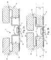
- Fig. 2a schematically represents, during a example of assembly operation, part (2), support (18) on which said part (2) is capable of being fixed and the boards (14) whose edges are provided with grooves (16), which each define a lower lip and a upper lip in a song of a board (14).
- the part (2) is represented when the wings (8) rise following the displacement of the boards (14) in the direction indicated by the horizontal arrows shown in dotted lines.
- moving planks (14) can be caused by the fact that the person who assembles the system pushes on said boards (14) to fit the wings (8) in the grooves (16).
- the direction of the wing elevation movement (8) during fitting is indicated in FIG. 2a by the two arrows upwards and in dotted lines.
- the grooves (16) include a chamfer at their lower edge. This chamfer facilitates assembly and is preferably such that its lower edge is at a height less than h 1 .
- the boards (10), or blades are for example made of wood exotic like ipe, padouk or native wood like larch or pine, possibly autoclaved, resinous or not, hard or tender. It will be clear to man of the trade that the boards (10) can be made of any wood without departing from the invention described here. Exotic woods like i regards and padouk are preferred because their expansion rate is lower than native woods like larch or pine, even if the tests carried out show that the system works well in both cases. It will be clear for those skilled in the art that, in the case of native wood, grooves can possibly be dug longitudinally in the lower surface of the boards (14) in order to reduce or prevent tiling of said boards (14) which may appear during expansion wood.
- the part (2) is first fixed on the support (6) by fixing means (12) and then the fitting described above is performed.
- Fig. 2b schematically represents the boards (16) fixed to the support (18) by the part (2).
- the visible gap (20) between the two boards (16) is sufficiently weak at a time to achieve the objective aesthetic sought-after layout fairly close to boards (16) between them and to allow the flow between the boards (16) of water in case of rain by example, from the surface of the boards (16) to a possible drainage system.
- Fig. 2b are also shown the differences in height h 3 and h ' 3 between the lowest point of each wing (8) and the base (4) of the fixing piece (2). It is these differences in height h 3 and h ' 3 which increase slightly following the expansion of the wood and decrease slightly following the contractions of the wood. These so-called height differences h 3 and h ' 3 are respectively greater than the height differences h 1 and h' 1 defined above. This characteristic, already known in the state of the art, effectively guarantees a blocking of the boards (16) by the wings (8).
- each wing (8) in the groove (16) is particularly important and constitutes an essential point of the wooden floor system according to the invention.
- the fulcrum of each wing (8) in the groove (16) is preferably but not necessarily at the end of the wing (8) of so as to produce an optimal bending moment.
- a wing (8) in contact over almost its entire length with a groove (16) would most likely cause problems tearing, deformation of the base (4) or creation of a game as described above.
- the object of the invention is especially to offer a solution to escape these problems.
- angles v and v ' which are, like the angles u and u', less than 90 degrees.
- Said angles v and v ' are the angles of a part fixing (2) as described here included between each wing (8) and its corresponding branch (6).
- the angles u and u ' are preferably between 80 degrees and 89 degrees, or between 84 degrees and 87 degrees, and preferably about 86 degrees. It will nevertheless clear to those skilled in the art that the angles described can below depend on the coefficient of radial expansion or axial of the wood or other characteristics of it, without departing from the invention described here.
- the wings (8) can or not to abut against the bottom of the grooves (16) without that this has no significant impact on the principle of the invention.
- each piece (2) is made of stainless steel, which guarantees durable resistance to weather corrosion, but not of any stainless steel. All steels do not offer properties appropriate elasticity and take any in no way guarantees sufficient retention of lower lip of the boards (14).
- a spring type stainless steel such as steel austenitic stainless steel type 301 defined by the standard of the American Iron and Steel Institute (AISI).
- AISI American Iron and Steel Institute
- stainless steel in which is formed each fixing part (2) contains a carbon concentration greater than 0.08 percent. The concentration as given here is a concentration in weight.
- the fixing part is made of steel austenitic stainless steel type 301 AISI whose class hardening is C1000, C1150 or C1300, said classes being defined by European standard EN 10088-2 and corresponding respectively to breaking loads of 1000 MPa to 1150 Mpa, from 1150 MPa to 1300 MPa and from 1300 MPa at 1500 MPa.
- EN 10088-2 European standard EN 10088-2
- the breaking strength ranges as given here is measured in the long sense over 20 mm x 80 mm test piece according to EN 10002-1.
- a steel comprising these characteristics is particularly well adapted thanks to its elasticity so that the wings (8) respond appropriately to wood movements.
- the fixing part (2) has undergone a heat treatment of surface to improve its mechanical characteristics of rigidity and possibly its aesthetics.
- the wings (8) of each part (2) are supported on a surface substantially horizontal of the groove (6) of one of the boards (14).
- substantially horizontal surface of a groove (6) it you have to understand a sufficiently inclined surface so to avoid as far as possible the pushing back of said board (14) during the nesting of the wings (8) in said groove (6) during an assembly operation.
- This can for example be a groove (6) in which each wing (8) is supported on an inclined surface according to an angle of less than 10 degrees from the horizontal, or preferably less than 5 degrees or even less than 3 degrees from the horizontal.
- the base (4) of each part (2) comprises at least one boss (22) on its surface capable of stiffening said base (4).
- the base (4) thus stiffened allows the forces on the part (2) due to expansion of the wood are essentially compensated by the movement of the wings (8) and not by a deformation of the base (4).
- the base (4) of each part (2) touches the support (18), that is to say that either said base (4) is directly in contact with the support (18) is indirectly in contact with the support (18), any thin thin element then being inserted between the base (4) of the part (2) and the support (18).
- the fact that the base (4) touches the support (18) makes the base (4) as rigid as possible by clamping the part (2) on the support (18).
- the first board (14) is first conventionally fixed by countersunk screw and plugging or thanks to a reverse screwing system. Then, fasteners (2) are partially fixed or completely on the support (18) in good places precise, and the second board (14) intended to be placed next to the first one is pushed or slid against the fasteners (2) already placed so that that the wings (8) of the parts (2) rise slightly and are introduced into the groove (s) (16) of the boards (14). If they were only partially, the screws for fixing the parts (2) to the support (18) are then tightened completely to maintain the assembly and, so on, the following boards (14) are placed side by side to form the floor.
- This example of assembly operation is advantageous because it allows to save time. It will be clear to the skilled person that the boards (14) can also be tilted during assembly to facilitate the introduction of the wings (8) into the grooves (16).
- Wooden floor system comprising planks (14) and fasteners (2) able to hold against a support (18) said boards (14) despite possible contractions and dilations thereof, while keeping said parts (2) not visible, where wings (8) are able to be introduced into a groove (16) in one of the boards (14), where each wing (8) is supported, when the system is assembled, substantially at a point of groove (16), and where, for each piece (2), the height of the branches (6) is less than the height of the most point bottom of the corresponding wing (8).
- Such systems of wooden floors are particularly well suited for a outdoor use, for example for floors of terrace.
Landscapes
- Engineering & Computer Science (AREA)
- Architecture (AREA)
- Life Sciences & Earth Sciences (AREA)
- Wood Science & Technology (AREA)
- Civil Engineering (AREA)
- Structural Engineering (AREA)
- Floor Finish (AREA)
Priority Applications (4)
| Application Number | Priority Date | Filing Date | Title |
|---|---|---|---|
| DE60327688T DE60327688D1 (de) | 2003-02-25 | 2003-02-25 | Holzfussbodensystem |
| ES03100449T ES2327725T3 (es) | 2003-02-25 | 2003-02-25 | Sistema de suelo de madera. |
| AT03100449T ATE431884T1 (de) | 2003-02-25 | 2003-02-25 | Holzfussbodensystem |
| EP03100449A EP1452665B1 (de) | 2003-02-25 | 2003-02-25 | Holzfussbodensystem |
Applications Claiming Priority (1)
| Application Number | Priority Date | Filing Date | Title |
|---|---|---|---|
| EP03100449A EP1452665B1 (de) | 2003-02-25 | 2003-02-25 | Holzfussbodensystem |
Publications (2)
| Publication Number | Publication Date |
|---|---|
| EP1452665A1 true EP1452665A1 (de) | 2004-09-01 |
| EP1452665B1 EP1452665B1 (de) | 2009-05-20 |
Family
ID=32748945
Family Applications (1)
| Application Number | Title | Priority Date | Filing Date |
|---|---|---|---|
| EP03100449A Expired - Lifetime EP1452665B1 (de) | 2003-02-25 | 2003-02-25 | Holzfussbodensystem |
Country Status (4)
| Country | Link |
|---|---|
| EP (1) | EP1452665B1 (de) |
| AT (1) | ATE431884T1 (de) |
| DE (1) | DE60327688D1 (de) |
| ES (1) | ES2327725T3 (de) |
Cited By (10)
| Publication number | Priority date | Publication date | Assignee | Title |
|---|---|---|---|---|
| AT502745B1 (de) * | 2005-10-31 | 2007-10-15 | Sebastian Fuchs | Befestigung von bohlen |
| ES2298006A1 (es) * | 2005-11-29 | 2008-05-01 | Maderas Del Alto Urgel, S.A. | Sistema de montaje de una estructura para suelo y elemento de fijacion. |
| FR2958957A1 (fr) * | 2010-04-15 | 2011-10-21 | Fribois | Piece de fixation pour plancher a lames |
| WO2011149371A1 (en) * | 2010-05-27 | 2011-12-01 | Iht, Lda. | Profile fixing accessory and system for fixing profiles using said accessory |
| CN103133464A (zh) * | 2011-11-22 | 2013-06-05 | 三星爱宝乐园 | 用于木材的固定设备和具有该设备的板面设施 |
| DE202012007345U1 (de) | 2012-07-30 | 2013-10-31 | Markus Rensburg | Verbindungsbauteil zum Aufbau einer im Wesentlichen ebenen Fläche |
| EP3696342A1 (de) * | 2019-02-13 | 2020-08-19 | Nexus Global Co., Ltd. | Doppelseitige bodenplattenmontage |
| AU2020227018B2 (en) * | 2019-09-02 | 2022-02-24 | James Hardie Technology Limited | Jointer system |
| IT202100002129A1 (it) * | 2021-02-02 | 2022-08-02 | Alessio Orsini | Rivestimento in legno a quadrotte per uso interno ed esterno |
| LU503433B1 (fr) * | 2023-02-03 | 2024-08-05 | Sinrj Invest S A R L | Système d'assemblage de planches sur solives |
Families Citing this family (1)
| Publication number | Priority date | Publication date | Assignee | Title |
|---|---|---|---|---|
| LU502159B1 (fr) | 2022-05-24 | 2023-11-30 | Sinrj Invest S A R L | Système d’assemblage de planches |
Citations (6)
| Publication number | Priority date | Publication date | Assignee | Title |
|---|---|---|---|---|
| FR1352653A (fr) * | 1963-04-05 | 1964-02-14 | United Carr Fastener Corp | Dispositif d'assemblage bout à bout d'éléments de construction tels que planchers, parois, plafonds |
| FR2630149A1 (fr) * | 1988-04-18 | 1989-10-20 | Placoplatre Sa | Accessoire de pose pour panneau de revetement, en particulier panneau de sol |
| EP0627562A1 (de) * | 1993-06-01 | 1994-12-07 | SIEMENS SOLAR GmbH | Klemmelement zur Befestigung flacher Körper über einer Unterlage |
| DE29507264U1 (de) * | 1995-05-02 | 1995-09-21 | Gudermann, Adolf, 87480 Weitnau | Trag- und Verbindungsprofil-Federschiene mit Entwässerungsfunktion zur Konstruktion von Holzterrassen, Balkonen, Plattformen usw. |
| DE29607962U1 (de) * | 1996-05-02 | 1996-07-18 | Rodriguez Lopez, Julio, Barcelona | Befestigungsvorrichtung für Holzböden im Außenbereich |
| EP1106842A1 (de) | 1999-12-03 | 2001-06-13 | Didier Fauré | Verbindungsvorrichtung für Holzleisten ohne sichtbare Schraube |
-
2003
- 2003-02-25 ES ES03100449T patent/ES2327725T3/es not_active Expired - Lifetime
- 2003-02-25 AT AT03100449T patent/ATE431884T1/de not_active IP Right Cessation
- 2003-02-25 DE DE60327688T patent/DE60327688D1/de not_active Expired - Lifetime
- 2003-02-25 EP EP03100449A patent/EP1452665B1/de not_active Expired - Lifetime
Patent Citations (6)
| Publication number | Priority date | Publication date | Assignee | Title |
|---|---|---|---|---|
| FR1352653A (fr) * | 1963-04-05 | 1964-02-14 | United Carr Fastener Corp | Dispositif d'assemblage bout à bout d'éléments de construction tels que planchers, parois, plafonds |
| FR2630149A1 (fr) * | 1988-04-18 | 1989-10-20 | Placoplatre Sa | Accessoire de pose pour panneau de revetement, en particulier panneau de sol |
| EP0627562A1 (de) * | 1993-06-01 | 1994-12-07 | SIEMENS SOLAR GmbH | Klemmelement zur Befestigung flacher Körper über einer Unterlage |
| DE29507264U1 (de) * | 1995-05-02 | 1995-09-21 | Gudermann, Adolf, 87480 Weitnau | Trag- und Verbindungsprofil-Federschiene mit Entwässerungsfunktion zur Konstruktion von Holzterrassen, Balkonen, Plattformen usw. |
| DE29607962U1 (de) * | 1996-05-02 | 1996-07-18 | Rodriguez Lopez, Julio, Barcelona | Befestigungsvorrichtung für Holzböden im Außenbereich |
| EP1106842A1 (de) | 1999-12-03 | 2001-06-13 | Didier Fauré | Verbindungsvorrichtung für Holzleisten ohne sichtbare Schraube |
Cited By (12)
| Publication number | Priority date | Publication date | Assignee | Title |
|---|---|---|---|---|
| AT502745B1 (de) * | 2005-10-31 | 2007-10-15 | Sebastian Fuchs | Befestigung von bohlen |
| ES2298006A1 (es) * | 2005-11-29 | 2008-05-01 | Maderas Del Alto Urgel, S.A. | Sistema de montaje de una estructura para suelo y elemento de fijacion. |
| ES2298006B1 (es) * | 2005-11-29 | 2009-08-03 | Maderas Del Alto Urgel, S.A. | Sistema de montaje de una estructura para suelo y elemento de fijacion. |
| FR2958957A1 (fr) * | 2010-04-15 | 2011-10-21 | Fribois | Piece de fixation pour plancher a lames |
| WO2011149371A1 (en) * | 2010-05-27 | 2011-12-01 | Iht, Lda. | Profile fixing accessory and system for fixing profiles using said accessory |
| CN103133464A (zh) * | 2011-11-22 | 2013-06-05 | 三星爱宝乐园 | 用于木材的固定设备和具有该设备的板面设施 |
| DE202012007345U1 (de) | 2012-07-30 | 2013-10-31 | Markus Rensburg | Verbindungsbauteil zum Aufbau einer im Wesentlichen ebenen Fläche |
| EP3696342A1 (de) * | 2019-02-13 | 2020-08-19 | Nexus Global Co., Ltd. | Doppelseitige bodenplattenmontage |
| AU2020227018B2 (en) * | 2019-09-02 | 2022-02-24 | James Hardie Technology Limited | Jointer system |
| IT202100002129A1 (it) * | 2021-02-02 | 2022-08-02 | Alessio Orsini | Rivestimento in legno a quadrotte per uso interno ed esterno |
| LU503433B1 (fr) * | 2023-02-03 | 2024-08-05 | Sinrj Invest S A R L | Système d'assemblage de planches sur solives |
| WO2024160543A1 (fr) * | 2023-02-03 | 2024-08-08 | Sinrj Invest S.À R.L. | Système d'assemblage de planches sur solives |
Also Published As
| Publication number | Publication date |
|---|---|
| DE60327688D1 (de) | 2009-07-02 |
| EP1452665B1 (de) | 2009-05-20 |
| ATE431884T1 (de) | 2009-06-15 |
| ES2327725T3 (es) | 2009-11-03 |
Similar Documents
| Publication | Publication Date | Title |
|---|---|---|
| EP1452665B1 (de) | Holzfussbodensystem | |
| EP3090850B1 (de) | Befestigungsmittel von belägen zur oberflächenbeschichtung und anwendung | |
| BE1003821A5 (fr) | Charniere pour abattant de w.c. | |
| FR2950371A1 (fr) | Systeme de fixation d'une dalle pour terrasse | |
| EP2270290A1 (de) | Befestigungsvorrichtung für Boden | |
| EP1936067A1 (de) | Wandverkleidung und Stabilisierungsteil für eine solche Wandverkleidung | |
| FR2967434A1 (fr) | Element de jonction pour parquet ou similaire | |
| FR2920645A1 (fr) | Chaussure | |
| FR2861764A1 (fr) | Dispositif a rupture de pont thermique comportant des moyens de reduction de la dilatation differentielle entre un corps exterieur et un corps interieur associe | |
| EP1362147A1 (de) | Montageteil für parkettstäbe aus holz | |
| FR3078086A1 (fr) | Systeme de platelage comportant des moyens de fixation d'un bandeau peripherique vertical. | |
| EP1528218B1 (de) | Führungsschienen-Anordnung eines Rollladens zur seitlichen Verhakung seines Panzers | |
| LU502159B1 (fr) | Système d’assemblage de planches | |
| EP2816931B1 (de) | Vorrichtung zur montage von gesimsen oder regalen | |
| WO2023001838A1 (fr) | Système de fixation invisible | |
| EP4056783B1 (de) | Vorrichtung zur befestigung von terrassendielen an eine unterlage | |
| WO2003014488A1 (fr) | Profile pour supporter et maintenir en tension un faux plafond muni d'une bordure, procede de mise en place dudit faux plafond | |
| EP2213813B1 (de) | Verfahren zur Herstellung eines Fußbodens aus einer Vielzahl von Massivholzlatten, und so hergestellter Fußboden | |
| FR2658848A1 (fr) | Element de support et de repartition de charges pour toit en tuiles plates et toit le comportant. | |
| WO2024213557A1 (fr) | Dispositif de blocage d'une latte de plancher ou de bardage | |
| EP0236586B1 (de) | Tragarme für Fachböden | |
| BE1017058A6 (fr) | Pieces d'angle et ensemble de margelle, en particulier pour piscine. | |
| EP0638343B1 (de) | Schuh-Auflageeinrichtung auf Skis | |
| EP4682326A1 (de) | Holzverkleidungsplatte | |
| FR2958957A1 (fr) | Piece de fixation pour plancher a lames |
Legal Events
| Date | Code | Title | Description |
|---|---|---|---|
| PUAI | Public reference made under article 153(3) epc to a published international application that has entered the european phase |
Free format text: ORIGINAL CODE: 0009012 |
|
| AK | Designated contracting states |
Kind code of ref document: A1 Designated state(s): AT BE BG CH CY CZ DE DK EE ES FI FR GB GR HU IE IT LI LU MC NL PT SE SI SK TR |
|
| AX | Request for extension of the european patent |
Extension state: AL LT LV MK RO |
|
| 17P | Request for examination filed |
Effective date: 20050222 |
|
| RAP1 | Party data changed (applicant data changed or rights of an application transferred) |
Owner name: DE VINCK, JUAN Owner name: PIETERS, RAPHAEL |
|
| RIN1 | Information on inventor provided before grant (corrected) |
Inventor name: DE VINCK, JUAN Inventor name: PIETERS, RAPHAEL |
|
| AKX | Designation fees paid |
Designated state(s): AT BE BG CH CY CZ DE DK EE ES FI FR GB GR HU IE IT LI LU MC NL PT SE SI SK TR |
|
| 17Q | First examination report despatched |
Effective date: 20061214 |
|
| GRAP | Despatch of communication of intention to grant a patent |
Free format text: ORIGINAL CODE: EPIDOSNIGR1 |
|
| GRAS | Grant fee paid |
Free format text: ORIGINAL CODE: EPIDOSNIGR3 |
|
| GRAA | (expected) grant |
Free format text: ORIGINAL CODE: 0009210 |
|
| REG | Reference to a national code |
Ref country code: DE Ref legal event code: R081 Ref document number: 60327688 Country of ref document: DE Owner name: PIETERS, RAPHAEL, BE Free format text: FORMER OWNER: D'HUYVETTER, IGNACE, BIERGES, BE Ref country code: DE Ref legal event code: R081 Ref document number: 60327688 Country of ref document: DE Owner name: VINCK, JUAN DE, CH Free format text: FORMER OWNER: D'HUYVETTER, IGNACE, BIERGES, BE |
|
| AK | Designated contracting states |
Kind code of ref document: B1 Designated state(s): AT BE BG CH CY CZ DE DK EE ES FI FR GB GR HU IE IT LI LU MC NL PT SE SI SK TR |
|
| REG | Reference to a national code |
Ref country code: GB Ref legal event code: FG4D Free format text: NOT ENGLISH |
|
| REG | Reference to a national code |
Ref country code: CH Ref legal event code: EP |
|
| REG | Reference to a national code |
Ref country code: IE Ref legal event code: FG4D Free format text: LANGUAGE OF EP DOCUMENT: FRENCH |
|
| REF | Corresponds to: |
Ref document number: 60327688 Country of ref document: DE Date of ref document: 20090702 Kind code of ref document: P |
|
| REG | Reference to a national code |
Ref country code: DE Ref legal event code: R096 Ref document number: 60327688 Country of ref document: DE Effective date: 20090702 |
|
| REG | Reference to a national code |
Ref country code: CH Ref legal event code: NV Representative=s name: BRAUNPAT BRAUN EDER AG |
|
| PG25 | Lapsed in a contracting state [announced via postgrant information from national office to epo] |
Ref country code: PT Free format text: LAPSE BECAUSE OF FAILURE TO SUBMIT A TRANSLATION OF THE DESCRIPTION OR TO PAY THE FEE WITHIN THE PRESCRIBED TIME-LIMIT Effective date: 20090920 Ref country code: AT Free format text: LAPSE BECAUSE OF FAILURE TO SUBMIT A TRANSLATION OF THE DESCRIPTION OR TO PAY THE FEE WITHIN THE PRESCRIBED TIME-LIMIT Effective date: 20090520 Ref country code: FI Free format text: LAPSE BECAUSE OF FAILURE TO SUBMIT A TRANSLATION OF THE DESCRIPTION OR TO PAY THE FEE WITHIN THE PRESCRIBED TIME-LIMIT Effective date: 20090520 |
|
| REG | Reference to a national code |
Ref country code: ES Ref legal event code: FG2A Ref document number: 2327725 Country of ref document: ES Kind code of ref document: T3 |
|
| PG25 | Lapsed in a contracting state [announced via postgrant information from national office to epo] |
Ref country code: SI Free format text: LAPSE BECAUSE OF FAILURE TO SUBMIT A TRANSLATION OF THE DESCRIPTION OR TO PAY THE FEE WITHIN THE PRESCRIBED TIME-LIMIT Effective date: 20090520 Ref country code: SE Free format text: LAPSE BECAUSE OF FAILURE TO SUBMIT A TRANSLATION OF THE DESCRIPTION OR TO PAY THE FEE WITHIN THE PRESCRIBED TIME-LIMIT Effective date: 20090820 |
|
| REG | Reference to a national code |
Ref country code: IE Ref legal event code: FD4D |
|
| PG25 | Lapsed in a contracting state [announced via postgrant information from national office to epo] |
Ref country code: IE Free format text: LAPSE BECAUSE OF FAILURE TO SUBMIT A TRANSLATION OF THE DESCRIPTION OR TO PAY THE FEE WITHIN THE PRESCRIBED TIME-LIMIT Effective date: 20090520 Ref country code: DK Free format text: LAPSE BECAUSE OF FAILURE TO SUBMIT A TRANSLATION OF THE DESCRIPTION OR TO PAY THE FEE WITHIN THE PRESCRIBED TIME-LIMIT Effective date: 20090520 Ref country code: EE Free format text: LAPSE BECAUSE OF FAILURE TO SUBMIT A TRANSLATION OF THE DESCRIPTION OR TO PAY THE FEE WITHIN THE PRESCRIBED TIME-LIMIT Effective date: 20090520 Ref country code: CZ Free format text: LAPSE BECAUSE OF FAILURE TO SUBMIT A TRANSLATION OF THE DESCRIPTION OR TO PAY THE FEE WITHIN THE PRESCRIBED TIME-LIMIT Effective date: 20090520 |
|
| PG25 | Lapsed in a contracting state [announced via postgrant information from national office to epo] |
Ref country code: SK Free format text: LAPSE BECAUSE OF FAILURE TO SUBMIT A TRANSLATION OF THE DESCRIPTION OR TO PAY THE FEE WITHIN THE PRESCRIBED TIME-LIMIT Effective date: 20090520 |
|
| PLBE | No opposition filed within time limit |
Free format text: ORIGINAL CODE: 0009261 |
|
| STAA | Information on the status of an ep patent application or granted ep patent |
Free format text: STATUS: NO OPPOSITION FILED WITHIN TIME LIMIT |
|
| PG25 | Lapsed in a contracting state [announced via postgrant information from national office to epo] |
Ref country code: BG Free format text: LAPSE BECAUSE OF FAILURE TO SUBMIT A TRANSLATION OF THE DESCRIPTION OR TO PAY THE FEE WITHIN THE PRESCRIBED TIME-LIMIT Effective date: 20090820 |
|
| 26N | No opposition filed |
Effective date: 20100223 |
|
| REG | Reference to a national code |
Ref country code: DE Ref legal event code: R097 Ref document number: 60327688 Country of ref document: DE Effective date: 20100223 |
|
| PG25 | Lapsed in a contracting state [announced via postgrant information from national office to epo] |
Ref country code: GR Free format text: LAPSE BECAUSE OF FAILURE TO SUBMIT A TRANSLATION OF THE DESCRIPTION OR TO PAY THE FEE WITHIN THE PRESCRIBED TIME-LIMIT Effective date: 20090821 |
|
| PG25 | Lapsed in a contracting state [announced via postgrant information from national office to epo] |
Ref country code: CY Free format text: LAPSE BECAUSE OF FAILURE TO SUBMIT A TRANSLATION OF THE DESCRIPTION OR TO PAY THE FEE WITHIN THE PRESCRIBED TIME-LIMIT Effective date: 20090520 |
|
| PG25 | Lapsed in a contracting state [announced via postgrant information from national office to epo] |
Ref country code: HU Free format text: LAPSE BECAUSE OF FAILURE TO SUBMIT A TRANSLATION OF THE DESCRIPTION OR TO PAY THE FEE WITHIN THE PRESCRIBED TIME-LIMIT Effective date: 20091121 |
|
| PG25 | Lapsed in a contracting state [announced via postgrant information from national office to epo] |
Ref country code: TR Free format text: LAPSE BECAUSE OF FAILURE TO SUBMIT A TRANSLATION OF THE DESCRIPTION OR TO PAY THE FEE WITHIN THE PRESCRIBED TIME-LIMIT Effective date: 20090520 |
|
| REG | Reference to a national code |
Ref country code: FR Ref legal event code: PLFP Year of fee payment: 14 |
|
| REG | Reference to a national code |
Ref country code: FR Ref legal event code: PLFP Year of fee payment: 15 |
|
| REG | Reference to a national code |
Ref country code: FR Ref legal event code: PLFP Year of fee payment: 16 |
|
| REG | Reference to a national code |
Ref country code: CH Ref legal event code: PCAR Free format text: NEW ADDRESS: HOLEESTRASSE 87, 4054 BASEL (CH) |
|
| PGFP | Annual fee paid to national office [announced via postgrant information from national office to epo] |
Ref country code: GB Payment date: 20220210 Year of fee payment: 20 Ref country code: DE Payment date: 20220214 Year of fee payment: 20 Ref country code: CH Payment date: 20220211 Year of fee payment: 20 |
|
| PGFP | Annual fee paid to national office [announced via postgrant information from national office to epo] |
Ref country code: NL Payment date: 20220223 Year of fee payment: 20 Ref country code: MC Payment date: 20220224 Year of fee payment: 20 Ref country code: LU Payment date: 20220221 Year of fee payment: 20 Ref country code: IT Payment date: 20220214 Year of fee payment: 20 Ref country code: FR Payment date: 20220221 Year of fee payment: 20 Ref country code: ES Payment date: 20220309 Year of fee payment: 20 Ref country code: BE Payment date: 20220221 Year of fee payment: 20 |
|
| REG | Reference to a national code |
Ref country code: DE Ref legal event code: R071 Ref document number: 60327688 Country of ref document: DE |
|
| REG | Reference to a national code |
Ref country code: CH Ref legal event code: PL |
|
| REG | Reference to a national code |
Ref country code: NL Ref legal event code: MK Effective date: 20230224 |
|
| REG | Reference to a national code |
Ref country code: BE Ref legal event code: MK Effective date: 20230225 |
|
| REG | Reference to a national code |
Ref country code: GB Ref legal event code: PE20 Expiry date: 20230224 |
|
| REG | Reference to a national code |
Ref country code: ES Ref legal event code: FD2A Effective date: 20230428 |
|
| PG25 | Lapsed in a contracting state [announced via postgrant information from national office to epo] |
Ref country code: GB Free format text: LAPSE BECAUSE OF EXPIRATION OF PROTECTION Effective date: 20230224 |
|
| P01 | Opt-out of the competence of the unified patent court (upc) registered |
Effective date: 20230511 |
|
| PG25 | Lapsed in a contracting state [announced via postgrant information from national office to epo] |
Ref country code: ES Free format text: LAPSE BECAUSE OF EXPIRATION OF PROTECTION Effective date: 20230226 |