EP1452687B1 - Rotorauswuchtung - Google Patents
Rotorauswuchtung Download PDFInfo
- Publication number
- EP1452687B1 EP1452687B1 EP03257848A EP03257848A EP1452687B1 EP 1452687 B1 EP1452687 B1 EP 1452687B1 EP 03257848 A EP03257848 A EP 03257848A EP 03257848 A EP03257848 A EP 03257848A EP 1452687 B1 EP1452687 B1 EP 1452687B1
- Authority
- EP
- European Patent Office
- Prior art keywords
- rotor
- offset
- centre
- axis
- machined
- Prior art date
- Legal status (The legal status is an assumption and is not a legal conclusion. Google has not performed a legal analysis and makes no representation as to the accuracy of the status listed.)
- Expired - Lifetime
Links
- 238000000034 method Methods 0.000 claims description 35
- 239000000463 material Substances 0.000 claims description 28
- 238000003754 machining Methods 0.000 claims description 16
- 230000003068 static effect Effects 0.000 claims description 8
- 230000004323 axial length Effects 0.000 claims description 3
- 238000004519 manufacturing process Methods 0.000 description 6
- 230000000712 assembly Effects 0.000 description 3
- 238000000429 assembly Methods 0.000 description 3
- 230000001788 irregular Effects 0.000 description 2
- 238000004364 calculation method Methods 0.000 description 1
- 238000010586 diagram Methods 0.000 description 1
- 230000000694 effects Effects 0.000 description 1
- 238000005516 engineering process Methods 0.000 description 1
- 210000004209 hair Anatomy 0.000 description 1
- 238000012986 modification Methods 0.000 description 1
- 230000004048 modification Effects 0.000 description 1
- 239000007787 solid Substances 0.000 description 1
- 238000011144 upstream manufacturing Methods 0.000 description 1
Images


Classifications
-
- F—MECHANICAL ENGINEERING; LIGHTING; HEATING; WEAPONS; BLASTING
- F01—MACHINES OR ENGINES IN GENERAL; ENGINE PLANTS IN GENERAL; STEAM ENGINES
- F01D—NON-POSITIVE DISPLACEMENT MACHINES OR ENGINES, e.g. STEAM TURBINES
- F01D5/00—Blades; Blade-carrying members; Heating, heat-insulating, cooling or antivibration means on the blades or the members
- F01D5/02—Blade-carrying members, e.g. rotors
- F01D5/027—Arrangements for balancing
-
- G—PHYSICS
- G01—MEASURING; TESTING
- G01M—TESTING STATIC OR DYNAMIC BALANCE OF MACHINES OR STRUCTURES; TESTING OF STRUCTURES OR APPARATUS, NOT OTHERWISE PROVIDED FOR
- G01M1/00—Testing static or dynamic balance of machines or structures
- G01M1/30—Compensating imbalance
- G01M1/34—Compensating imbalance by removing material from the body to be tested, e.g. from the tread of tyres
-
- Y—GENERAL TAGGING OF NEW TECHNOLOGICAL DEVELOPMENTS; GENERAL TAGGING OF CROSS-SECTIONAL TECHNOLOGIES SPANNING OVER SEVERAL SECTIONS OF THE IPC; TECHNICAL SUBJECTS COVERED BY FORMER USPC CROSS-REFERENCE ART COLLECTIONS [XRACs] AND DIGESTS
- Y10—TECHNICAL SUBJECTS COVERED BY FORMER USPC
- Y10T—TECHNICAL SUBJECTS COVERED BY FORMER US CLASSIFICATION
- Y10T29/00—Metal working
- Y10T29/49—Method of mechanical manufacture
- Y10T29/49316—Impeller making
- Y10T29/4932—Turbomachine making
- Y10T29/49325—Shaping integrally bladed rotor
-
- Y—GENERAL TAGGING OF NEW TECHNOLOGICAL DEVELOPMENTS; GENERAL TAGGING OF CROSS-SECTIONAL TECHNOLOGIES SPANNING OVER SEVERAL SECTIONS OF THE IPC; TECHNICAL SUBJECTS COVERED BY FORMER USPC CROSS-REFERENCE ART COLLECTIONS [XRACs] AND DIGESTS
- Y10—TECHNICAL SUBJECTS COVERED BY FORMER USPC
- Y10T—TECHNICAL SUBJECTS COVERED BY FORMER US CLASSIFICATION
- Y10T29/00—Metal working
- Y10T29/49—Method of mechanical manufacture
- Y10T29/49762—Center locating and shaping
-
- Y—GENERAL TAGGING OF NEW TECHNOLOGICAL DEVELOPMENTS; GENERAL TAGGING OF CROSS-SECTIONAL TECHNOLOGIES SPANNING OVER SEVERAL SECTIONS OF THE IPC; TECHNICAL SUBJECTS COVERED BY FORMER USPC CROSS-REFERENCE ART COLLECTIONS [XRACs] AND DIGESTS
- Y10—TECHNICAL SUBJECTS COVERED BY FORMER USPC
- Y10T—TECHNICAL SUBJECTS COVERED BY FORMER US CLASSIFICATION
- Y10T29/00—Metal working
- Y10T29/49—Method of mechanical manufacture
- Y10T29/49764—Method of mechanical manufacture with testing or indicating
- Y10T29/49771—Quantitative measuring or gauging
- Y10T29/49776—Pressure, force, or weight determining
Definitions
- This invention relates to rotor balancing and in particular the permanent balancing of rotors by the removal of material from the rotor to correct unbalance.
- Rotating components such as wheels, crankshafts, drive shafts, gas turbine engine rotors etc, are balanced using various balancing methods which can be considered as either permanent or non permanent.
- permanent balancing material is removed from the component to be balanced (for example, as described in US 2954711 [Hack ], in which holes are drilled in a disc in a non-symmetrical pattern) while in non-permanent methods balanced weights are added to the rotary component.
- Rotating components can be balanced by the removal of material from specific balancing lands provided on the component to be balanced (for example, as described in EP1188900 , [General Electric]), or by the method of mass centering where location features, for example bearing surfaces, are offset machined to compensate for unbalance.
- location features for example bearing surfaces
- the location features of the component are machined to their final dimensions such that the position of the axis of rotation, as determined by the location features, is made to be coincident with the center of mass of the component.
- Such a method is discussed in DE 100 35 030 A1 [DaimlerChrysler ], in which the axis of a bore of a disc is offset from a nominal geometric axis in order to balance the disc.
- One disadvantage is that the component to be balanced is heavier than it would otherwise have to be because of the provision of relatively large balancing lands.
- Another disadvantage is that slave location features are required to hold the component while the normal location features aremachined to their final dimensions. The requirement for relatively large lands and slave location features can add significantly to the weight of the component and this is a significant consideration in gas turbine aero engine applications.
- Gas turbine engine rotors have traditionally been balanced using the weight variation present in a set of aerofoil blades to correct not only the disc unbalance but also that of the blades. This has been possible because the rotor blades have traditionally been attachably/detachably mounted in slots provided in the rim of the rotor disc so that the blades can be distributed around the circumference of the disc in such a way that the variations in their weight can be used to compensate for disc and blade unbalance. The net effect of this approach is a balanced bladed disc assembly having zero unbalance.
- Bladed discs also referring to as blisks, or bliscs
- Blisks may be machined from solid, but more usually the blades are friction welded to the rim of the disc. Blisks have a number of advantages when compared with more traditional blade and disc assemblies since the weight associated with the mounting features of the blade and disc can be eliminated from the rotor, and therefore blisks are increasingly used in modem gas turbine engines.
- blisks presents a new problem to the gas turbine engine designer in terms of rotor balancing since the method of using the mass variation present in a set of blades and balancing the rotor assembly accordingly is no longer available.
- the use of mass centering is not desirable for the aforementioned reasons, and therefore there is a requirement for a more appropriate balancing method for balancing rotors, and blisks in particular.
- the weight of the rotor can be significantly reduced by significantly reducing the size of the balance correction lands present on the rotor. It is preferable that the above method is used to balance the rotor within predetermined limits as determined by the manufacturing tolerances for the rotor, and then correct relatively minor levels of unbalance by offset machining the balance correction lands to more finely balance the rotor. In this way the method of the present invention can be used to correct the major part of the unbalance in the rotor such that the size of the balance lands required for fine correction can be significantly reduced.
- the balancing method of the present invention is different to that of mass centring since in the present method the rotor is machined to its final dimensions such that the centre of mass of the rotor is moved to be coincident with the axis of rotation, while in mass centring it is the axis of rotation of the rotor that is moved to be coincident with the centre of mass by machining the rotor location features.
- the method comprises the step of determining an offset representative of the eccentricity of the centre of mass of the unbalanced rotor with respect to the said axis of rotation, and applying the offset to machine the rotor to its final dimensions such that the geometric centre of at least part of the rotor is offset with respect to the axis of rotation to balance the rotor.
- the offset is preferably 1mm or less and therefore the unbalanced rotor is first pre-machined to allow an offset of 1 mm or less to be applied to the rotor during final machining.
- the radially outer periphery of the rotor is machined such that its geometric centre is offset with respect to the said axis of rotation by an amount equal to the said offset dimension and in a direction opposite to that of the said eccentricity. In this way rotor unbalance may be corrected by machining either the bore or the outer radially annular part of the rotor or both.
- the offset dimension or eccentricity is determined by the static unbalance of the unbalanced rotor, the average diameter of the material to be removed and the length of the rotor over which material is to be removed.
- the offset required to correct the unbalance of the rotor is calculated using the above formula.
- the method of the present invention is particularly suitable where the offset dimension required to correct unbalance in the rotor is relatively large in comparison with the manufacturing tolerance of the part of the component to be machined.
- the rotor may comprise a turbine disc or compressor, preferably a gas turbine engine disc, more preferably a turbine or compressor blisk, that is to say a disc having integrally formed blades instead of attachably/detachably mounted blades.
- a turbine disc or compressor preferably a gas turbine engine disc, more preferably a turbine or compressor blisk, that is to say a disc having integrally formed blades instead of attachably/detachably mounted blades.
- the level of unbalance is relatively low and offset dimensions calculated in accordance with the above mentioned formula are typically of the same order as the manufacturing tolerance and therefore it may not be economically practical to reduce initial unbalance in such assemblies.
- the high level of unbalance commonly found in blisk results in offset dimensions much greater than the manufacturing tolerances required and therefore the method of the present invention provides a practical and cost effective way of reducing initial blisk unbalance.
- the method of the present invention therefore has particular advantages where the initial unbalance of the rotor is relatively high and/or in
- the present invention also contemplates a rotor balanced according to the above method and in particular a gas turbine engine disc or blisk balanced according to the method of the invention.
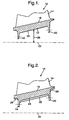
- a rotor stage of a gas turbine engine comprises a blisk 10 which comprises a disc part 12 and a plurality of circumferentially spaced aerofoil blades 14 which extend radially outwards from the disc rim 16.
- the blisk is provided with forward and rearward mounting flanges, 18 and 20 respectively, for mounting the blisk to a shaft (not shown) of the gas turbine engine for rotation about the engine axis 22.
- the rotor stage 10 may be a compressor rotor stage or a turbine rotor stage since the method of the present invention is applicable to balancing both turbine and compressor rotors.
- the blisk is machined so that the average diameter 26 of the blisk's radially inner surface 24, within the central bore of the disk, is slightly smaller than the final diameter of the finished disc.
- the undersize bore diameter is indicated by the line 28 which represents the bore surface prior to finish machining the blisk to its final dimensions.
- the diameter of the bore of the blisk is about 1 mm undersize prior to finish machining.
- Figure 3 shows the internal circumference of a rotor having a bore of irregular shape.
- the view of Figure 3 is similar to that of Figures 1 and 2 in the sense that it shows an axi-symmetric cross section view of the rotor.
- the offset (e) is shown applied to the outline of the rotary components such that the solid line 30 represents the outline of the inner diameter before finish machining and the chained line 32 represents the outline of the internal diameter after the component has been finish machined to its final dimensions. It is to be understood that the offset (e) results in different amounts of material being removed from different parts of the inner diameter around its circumference, since the offset is applied in the direction (angular position) of the centre of mass of the rotary component prior to finish machining.
- Figure 4a is a vector diagram showing the direction, or angular offset, of the centre of mass of the rotor to be balanced prior to finish machining.
- the angular offset vector 34 is shown with respect to a coordinate reference frame passing through the axis of rotation of the rotor represented by the point 36 in the drawing of Figure 4a .
- the diameter 38 of the outer circumference 40 of the rotary component is greater than is required in the finish component to allow material to be removed for balancing.
- the geometric centre of the outer circumference 40 and the axis of rotation are coincident and represented by the point 42 at the centre of the cross hairs 44.
- the outer circumference 46 of the finish machined rotary component has a geometric centre represented by point 48 in the drawing which is offset from the geometric centre 42 by a distance 50 as determined by the above mentioned equation.
- the distance between the geometric centres 42 and 48 is equivalent to the eccentricity of the mass centre of the unbalanced rotary component having the external circumference 40.
- the component is to be balanced by removing material from the outer circumference and therefore the offset 50 is applied in a direction diametrically opposite that of the unbalance vector 34, that is to say with an offset angle equal to that of the vector 34 + 180°.
- the material in the region 52 between the outer circumference 40 of the unbalanced rotary component and the circumference 46 of the finish machined component is removed in the balancing process.
- the cutter may simply be centred on the geometric centre 48 to remove the unwanted material in the region 52 bounded by the circumferences 40 and 46.
- the cutter is controlled by a numerically controlled machine tool.
- the offset is applied in the direction of the vector 34 where material is to be removed from the surface of the inner circumference of an internal bore, such as that defined by surface 24 in the blisk 10 of Figures 1 and 2 .
- material is removed along substantially the whole length of the component to be balanced and in the rotor of Figures 1 and 2 material may be removed in the region between the flanges 18 and 20 and on the other sides of the flanges as indicated by lines 28 in Figure 2 . Material may also be removed additionally or alternatively from the gas washed surface at the rim 16 of the disc between the aerofoil blades 14.
- Figure 5 shows alternative blisk arrangement where the disc part 12 of the blisk extends radially and axially and may be offset machined along the downstream 56 side of the blisk, as indicated to the right of the drawing in Figure 5 , or on the upstream side 54 as indicated to the left of the drawing in Figure 5 .
- the invention may be used for balancing components other than blisk rotor stages in gas turbine engines, and may be used for balancing any type of rotational component where the initial unbalance is relatively high and generally too high for correcting by known methods of machining balance correction lands.
Landscapes
- Engineering & Computer Science (AREA)
- Physics & Mathematics (AREA)
- General Physics & Mathematics (AREA)
- Mechanical Engineering (AREA)
- General Engineering & Computer Science (AREA)
- Testing Of Balance (AREA)
- Turbine Rotor Nozzle Sealing (AREA)
- Manufacture Of Motors, Generators (AREA)
- Structures Of Non-Positive Displacement Pumps (AREA)
Claims (5)
- Verfahren zum Auswuchten eines Rotors (10) mit einem radial inneren Umfang und einem radial äußeren Umfang, wobei das Verfahren die folgenden Schritte aufweist:Bestimmen der Position des Massenzentrums eines Rotors (10), der auszuwuchten ist, bevor der Rotor (10) auf seine Endabmessungen bearbeitet wird,Bearbeiten des Rotors (10) auf seine Endabmessungen durch Abtragen von Material von mindestens dem radial inneren Umfang des Rotors oder dem radial äußeren Umfang des Rotors im wesentlichen entlang der Länge des Rotors (10) in einer axialen Richtung, wodurch das Massenzentrum des Rotors (10) im wesentlichen coinzident mit der Drehachse (22) des Rotors eingestellt wird,gekennzeichnet durch den Schritt der Bestimmung eines Versatzes (e), der die Exzentrizität des Massenzentrums des nicht ausgewuchteten Rotors (10) mit Bezug auf die genannte Drehachse (22) repräsentiert, und des Anwendens des Versatzes (e) zum Bearbeiten des Rotors (10) auf seine Endabmessungen derart, dass das geometrische Zentrum mindestens eines Teils des Rotors (10) mit Bezug auf die Drehachse (22) versetzt ist, um den Rotor (10) auszuwuchten, wobei der Rotor (10) eine Nabe mit einer Bohrung aufweist, und die Bohrung so bearbeitet wird, dass er geometrisches Zentrum mit Bezug auf die genannte Drehachse (22) um ein gleiches Maß wie die Versatzdimension (e) und in Richtung der genannten Exzentrizität versetzt wird.
- Verfahren nach Anspruch 1, wobei die genannte Bohrung auf ihre Endabmessung durch ein Maschinenschneidwerkzeug bearbeitet wird, das auf das genannte Massenzentrum des nicht ausgewuchteten Rotors (10) zentriert ist.
- Verfahren nach Anspruch 1, wobei der radial äußere Umfang des Rotors (10) und der innere Umfang so bearbeitet werden, dass sein geometrisches Zentrum mit Bezug auf die genannte Drehachse (22) um ein Maß versetzt ist, das der genannten Versatzdimension (e) ist und in einer Richtung entgegengesetzt zu derjenigen der genannten Exzen-trizität erfolgt.
- Verfahren nach irgendeinem vorhergehenden Anspruch, wobei die Versatzdimension (e) oder Exzentrizität durch die statische Unwucht des nicht ausgewuchteten Rotors, des mittleren Durchmessers (D) des abzutragenden Materials und die Länge des Rotors bestimmt wird, über welche Material abzutragen ist.
- Verfahren nach Anspruch 4, wobei das Versatzmaß (e) bzw. die Exzentrizität durch die Formel bestimmt wird: e = (4 x U) / (π x D2 x L x ρ), wobei U die statische Unwucht des nicht ausgewuchteten Rotors (10) ist, D der mittlere Durchmesser des vom nicht ausgewuchteten Rotor (10) abzutragenden Materials ist, L die axiale Länge des Rotors ist, über welche Material abzutragen ist, und ρ die Dichte des Rotormaterials ist.
Applications Claiming Priority (2)
| Application Number | Priority Date | Filing Date | Title |
|---|---|---|---|
| GB0304473 | 2003-02-27 | ||
| GB0304473A GB2398882B (en) | 2003-02-27 | 2003-02-27 | Rotor balancing |
Publications (3)
| Publication Number | Publication Date |
|---|---|
| EP1452687A2 EP1452687A2 (de) | 2004-09-01 |
| EP1452687A3 EP1452687A3 (de) | 2006-09-13 |
| EP1452687B1 true EP1452687B1 (de) | 2012-08-08 |
Family
ID=9953757
Family Applications (1)
| Application Number | Title | Priority Date | Filing Date |
|---|---|---|---|
| EP03257848A Expired - Lifetime EP1452687B1 (de) | 2003-02-27 | 2003-12-13 | Rotorauswuchtung |
Country Status (3)
| Country | Link |
|---|---|
| US (1) | US7069654B2 (de) |
| EP (1) | EP1452687B1 (de) |
| GB (1) | GB2398882B (de) |
Families Citing this family (22)
| Publication number | Priority date | Publication date | Assignee | Title |
|---|---|---|---|---|
| FR2886012B1 (fr) * | 2005-05-23 | 2007-07-06 | Snecma Moteurs Sa | Procede de calibrage en masse de pieces destinees a etre montees en peripherie d'un rotor |
| GB2438642B (en) * | 2006-06-01 | 2008-04-09 | Rolls Royce Plc | Rotor unbalance correction |
| GB2450936B (en) * | 2007-07-13 | 2010-01-20 | Rolls Royce Plc | Bladed rotor balancing |
| US8328519B2 (en) * | 2008-09-24 | 2012-12-11 | Pratt & Whitney Canada Corp. | Rotor with improved balancing features |
| US8342804B2 (en) * | 2008-09-30 | 2013-01-01 | Pratt & Whitney Canada Corp. | Rotor disc and method of balancing |
| US8316523B2 (en) | 2009-10-01 | 2012-11-27 | Pratt & Whitney Canada Corp. | Method for centering engine structures |
| IT1396520B1 (it) | 2009-12-10 | 2012-12-14 | Nuovo Pignone Spa | Accoppiamento per bilanciamento rotore |
| CN101832840B (zh) * | 2010-04-29 | 2011-11-09 | 中国燃气涡轮研究院 | 一种铸造式整体叶盘静平衡调整方法 |
| GB2481582A (en) * | 2010-06-28 | 2012-01-04 | Rolls Royce Plc | A method for predicting initial unbalance in a component such as a blisk |
| CA2761208C (en) | 2010-12-08 | 2019-03-05 | Pratt & Whitney Canada Corp. | Blade disk arrangement for blade frequency tuning |
| US9511457B2 (en) | 2012-02-09 | 2016-12-06 | Pratt & Whitney Canada Corp. | Gas turbine engine rotor balancing |
| WO2015088620A2 (en) * | 2013-09-26 | 2015-06-18 | United Technologies Corporation | Rotating component balance ring |
| US10247003B2 (en) * | 2013-09-26 | 2019-04-02 | United Technologies Corporation | Balanced rotating component for a gas powered engine |
| US9988146B2 (en) | 2013-11-08 | 2018-06-05 | Sikorsky Aircraft Corporation | Rotor balancing apparatus |
| US9624775B2 (en) | 2014-05-30 | 2017-04-18 | Rolls-Royce Plc | Developments in or relating to rotor balancing |
| EP2792849B1 (de) * | 2014-05-30 | 2016-07-13 | Rolls-Royce plc | Entwicklungen an oder im Zusammenhang mit Rotorauswuchtung |
| EP2957792B1 (de) * | 2014-06-20 | 2020-07-29 | United Technologies Corporation | Rotor mit reduzierter schwingungsreaktion für eine gasbetriebene turbine |
| US9638037B2 (en) | 2014-11-03 | 2017-05-02 | Pratt & Whitney Canada Corp. | Method of balancing a gas turbine engine rotor |
| US10323519B2 (en) * | 2016-06-23 | 2019-06-18 | United Technologies Corporation | Gas turbine engine having a turbine rotor with torque transfer and balance features |
| DE102018102751B3 (de) * | 2018-02-07 | 2019-02-21 | Schenck Rotec Gmbh | Verfahren zur Messung der Unwucht wellenelastischer Rotoren mittels wegmessender Sensoren |
| CN111982402B (zh) * | 2020-04-09 | 2021-11-05 | 西北工业大学 | 考虑初始不平衡量的航空发动机转子零件选配优化方法 |
| US12312091B2 (en) * | 2022-10-06 | 2025-05-27 | Archer Aviation Inc. | Systems and methods for improved gearboxes for evtol aircraft |
Family Cites Families (13)
| Publication number | Priority date | Publication date | Assignee | Title |
|---|---|---|---|---|
| US2327606A (en) * | 1941-03-05 | 1943-08-24 | Clare F Saltz | Balancing rotating element |
| US2804775A (en) * | 1950-03-31 | 1957-09-03 | Schenck Gmbh Carl | Means for the balancing of revolvable bodies |
| US3076363A (en) * | 1950-11-18 | 1963-02-05 | Schenck Gmbh Carl | Means for machining rotating workpieces |
| US2954711A (en) * | 1957-11-07 | 1960-10-04 | Schenck Gmbh Carl | Method and machines for balancing rotors |
| US4170896A (en) * | 1978-03-20 | 1979-10-16 | Summa Corporation | Balancing of high-speed shafts |
| JPS5783746A (en) * | 1980-11-11 | 1982-05-25 | Matsushita Electric Ind Co Ltd | Correction method of dynamic unbalance of rotating body |
| BR0000269A (pt) * | 1999-01-12 | 2001-09-04 | Meritor Heavy Vehicle Sys Ltd | Tambor de freio balanceado e método para sua produção |
| DE19910276A1 (de) * | 1999-03-09 | 2000-09-14 | Schlafhorst & Co W | Spinnrotor für Offenend-Spinnmaschinen und Verfahren zur Herstellung des Spinnrotors |
| US6375421B1 (en) * | 2000-01-31 | 2002-04-23 | General Electric Company | Piggyback rotor blisk |
| DE10035030A1 (de) * | 2000-07-19 | 2001-09-13 | Daimler Chrysler Ag | Verfahren zum Auswuchten von rotierenden Körpern |
| US6354780B1 (en) * | 2000-09-15 | 2002-03-12 | General Electric Company | Eccentric balanced blisk |
| JP2002166702A (ja) * | 2000-12-01 | 2002-06-11 | Honda Motor Co Ltd | バランスが調整されたホイールおよびその製造方法 |
| GB0227520D0 (en) * | 2002-11-26 | 2002-12-31 | Bombardier Transp Gmbh | Off-centre machining apparatus and method |
-
2003
- 2003-02-27 GB GB0304473A patent/GB2398882B/en not_active Expired - Fee Related
- 2003-12-13 EP EP03257848A patent/EP1452687B1/de not_active Expired - Lifetime
- 2003-12-23 US US10/743,002 patent/US7069654B2/en not_active Expired - Lifetime
Also Published As
| Publication number | Publication date |
|---|---|
| GB2398882B (en) | 2007-09-05 |
| US7069654B2 (en) | 2006-07-04 |
| GB0304473D0 (en) | 2003-04-02 |
| GB2398882A (en) | 2004-09-01 |
| EP1452687A2 (de) | 2004-09-01 |
| US20040168291A1 (en) | 2004-09-02 |
| EP1452687A3 (de) | 2006-09-13 |
Similar Documents
| Publication | Publication Date | Title |
|---|---|---|
| US7069654B2 (en) | Rotor balancing | |
| JP4837203B2 (ja) | 偏心によりバランスされたブリスク | |
| US11215055B2 (en) | Gas turbine engine rotor balancing | |
| KR100468982B1 (ko) | 일체식블레이드형로터의에어포일을가공하는데사용하는고정물및에어포일표면의가공방법 | |
| US7637010B2 (en) | Methods for machining turbine engine components | |
| EP1930121B1 (de) | Verfahren zur Bearbeitung von Turbineschaufeln mittels Scheibenwerkzeugen | |
| CA2905140C (en) | Method of balancing a gas turbine engine rotor | |
| US8286348B2 (en) | Method of manufacturing and refinishing integrally bladed rotors | |
| JP2010230012A (ja) | 遠心圧縮機のロータの改良された製造方法 | |
| JPH0641779B2 (ja) | 回転部品の釣合をとる装置 | |
| EP3152403B1 (de) | Turbinen-blisk und verfahren zur herstellung davon | |
| EP1862698B1 (de) | Korrektur des Unwuchts eines Rotors | |
| CA2708467C (en) | Method and apparatus for providing rotor discs | |
| EP0666407B1 (de) | Integrale Schaufel-Rotoreinheit | |
| EP2074287B1 (de) | Rotorelement und verfahren zur herstellung des rotorelements | |
| JP2004052616A (ja) | 過給機のタービン翼の加工方法 | |
| GB2428396A (en) | A method of manufacturing an article with a reference datum feature | |
| WO2024124017A1 (en) | Method of balancing a turbo expander / booster wheel | |
| EP2792849B1 (de) | Entwicklungen an oder im Zusammenhang mit Rotorauswuchtung | |
| WO2018119391A1 (en) | Turbocharger and turbine wheel |
Legal Events
| Date | Code | Title | Description |
|---|---|---|---|
| PUAI | Public reference made under article 153(3) epc to a published international application that has entered the european phase |
Free format text: ORIGINAL CODE: 0009012 |
|
| AK | Designated contracting states |
Kind code of ref document: A2 Designated state(s): AT BE BG CH CY CZ DE DK EE ES FI FR GB GR HU IE IT LI LU MC NL PT RO SE SI SK TR |
|
| AX | Request for extension of the european patent |
Extension state: AL LT LV MK |
|
| PUAL | Search report despatched |
Free format text: ORIGINAL CODE: 0009013 |
|
| AK | Designated contracting states |
Kind code of ref document: A3 Designated state(s): AT BE BG CH CY CZ DE DK EE ES FI FR GB GR HU IE IT LI LU MC NL PT RO SE SI SK TR |
|
| AX | Request for extension of the european patent |
Extension state: AL LT LV MK |
|
| 17P | Request for examination filed |
Effective date: 20070127 |
|
| AKX | Designation fees paid |
Designated state(s): DE FR GB |
|
| 17Q | First examination report despatched |
Effective date: 20070620 |
|
| RBV | Designated contracting states (corrected) |
Designated state(s): DE FR |
|
| REG | Reference to a national code |
Ref country code: DE Ref legal event code: R079 Ref document number: 60341728 Country of ref document: DE Free format text: PREVIOUS MAIN CLASS: F01D0005020000 Ipc: G01M0001340000 |
|
| RIC1 | Information provided on ipc code assigned before grant |
Ipc: G01M 1/34 20060101AFI20120130BHEP Ipc: F01D 5/02 20060101ALI20120130BHEP |
|
| GRAP | Despatch of communication of intention to grant a patent |
Free format text: ORIGINAL CODE: EPIDOSNIGR1 |
|
| GRAS | Grant fee paid |
Free format text: ORIGINAL CODE: EPIDOSNIGR3 |
|
| GRAA | (expected) grant |
Free format text: ORIGINAL CODE: 0009210 |
|
| AK | Designated contracting states |
Kind code of ref document: B1 Designated state(s): DE FR |
|
| REG | Reference to a national code |
Ref country code: DE Ref legal event code: R082 Ref document number: 60341728 Country of ref document: DE Representative=s name: FLEUCHAUS & GALLO PARTNERSCHAFT MBB, DE Ref country code: DE Ref legal event code: R082 Ref document number: 60341728 Country of ref document: DE Representative=s name: FLEUCHAUS & GALLO PARTNERSCHAFT, DE |
|
| REG | Reference to a national code |
Ref country code: DE Ref legal event code: R096 Ref document number: 60341728 Country of ref document: DE Effective date: 20121206 |
|
| PLBE | No opposition filed within time limit |
Free format text: ORIGINAL CODE: 0009261 |
|
| STAA | Information on the status of an ep patent application or granted ep patent |
Free format text: STATUS: NO OPPOSITION FILED WITHIN TIME LIMIT |
|
| 26N | No opposition filed |
Effective date: 20130510 |
|
| REG | Reference to a national code |
Ref country code: DE Ref legal event code: R097 Ref document number: 60341728 Country of ref document: DE Effective date: 20130510 |
|
| REG | Reference to a national code |
Ref country code: FR Ref legal event code: PLFP Year of fee payment: 13 |
|
| REG | Reference to a national code |
Ref country code: FR Ref legal event code: PLFP Year of fee payment: 14 |
|
| REG | Reference to a national code |
Ref country code: FR Ref legal event code: CA Effective date: 20170517 |
|
| REG | Reference to a national code |
Ref country code: FR Ref legal event code: PLFP Year of fee payment: 15 |
|
| PGFP | Annual fee paid to national office [announced via postgrant information from national office to epo] |
Ref country code: FR Payment date: 20181226 Year of fee payment: 16 |
|
| PGFP | Annual fee paid to national office [announced via postgrant information from national office to epo] |
Ref country code: DE Payment date: 20181231 Year of fee payment: 16 |
|
| REG | Reference to a national code |
Ref country code: DE Ref legal event code: R119 Ref document number: 60341728 Country of ref document: DE |
|
| PG25 | Lapsed in a contracting state [announced via postgrant information from national office to epo] |
Ref country code: DE Free format text: LAPSE BECAUSE OF NON-PAYMENT OF DUE FEES Effective date: 20200701 Ref country code: FR Free format text: LAPSE BECAUSE OF NON-PAYMENT OF DUE FEES Effective date: 20191231 |